
Polymeric Micro Check Valve for Glaucoma Treatment
Considering Rate of Aqueous Humor Formation
Chang-Ju Park
1
, Jaekwon Lee
2
, Byungphil Mun
3
, Jae-Yong An
4
, Seunghwan Moon
2
,
and Jong-Hyun Lee
1,2
1
Department of Medical System Engineering, Gwangju Institute of Science and Technology, Gwangju,
Republic of Korea
2
School of Mechatronics, Gwangju Institute of Science and Technology, Gwangju, Republic of Korea
3
Production Engineering Research Institute, LG Electronics, Seoul, Republic of Korea
4
Future Device R&D Department New Device Team, LG Electronics, Seoul, Republic of Korea
Keywords: Glaucoma Drainage Device, Intraocular Pressure, Micro Check Valve, Polymeric, Cracking Pressure,
Aqueous Humor Formation.
Abstract: This paper describes a novel glaucoma drainage device (GDD) to regulate intraocular pressure (IOP)
considering the rate of aqueous humor formation. The device functionally consists of a polymeric cannula
(silicone tube) and a micro check valve (PDMS: polydimethylsiloxane). The check valve has three layers: a
top layer (cover), which has rounded edges to reduce fibrosis, an intermediate layer (thin movable valve
membrane), and a bottom layer (base plate). A feedforward channel is employed in the top layer to prevent
reverse flow by compensating the pressure of the outlet channel. The thickness of thin the PDMS membrane
was determined considering the cracking pressure and the rate of aqueous humor formation. The cracking
pressure in-vitro test was conducted at 15 mmHg, which lies within the normal intraocular pressure range (10
~ 20 mmHg). The experimental mean value and standard deviation of the flow rate at the cracking pressure
was 2.18 ± 0.69 µL/min, which is confirmed to cover the rate of aqueous humor formation in the normal
human eye (1.5 ~ 3.4 µL/min). Flow in a reverse direction was not observed.
1 INTRODUCTION
Glaucoma is an eye disorder associated with
abnormally increased intraocular pressure (IOP) due
to occlusion of Schlemm’s canal. It permanently
induces resultant visual field loss and progressive
blindness by damaging the optic nerve system. Three
types of glaucoma treatment methods are mainly
used to lower the IOP, including medication, laser
surgery, and glaucoma surgery depending on the
severity. One of the methods of refractory glaucoma
treatment is a drainage device to surgically lower the
IOP (Shuchi and Louis, 2010). Many researchers
have worked to develop such a drainage device for
glaucoma patients. Typically, Molteno, Krupin,
Baerveldt, and Ahmed valves are commercially
available devices, which usually consist of two
components, namely, a cannula and a base plate. The
plate is fixed onto the cornea with sutures, and the
cannula shunts aqueous humour from the anterior
chamber into the reservoir (Brian A Francis et al.,
1998).
Recently, many efforts to develop a drainage
device using microfabrication technologies, called
microelectromechanical systems (MEMS), have
taken advantage of size reduction and batch
processes. In particular, micro check valves are
effective drainage valves for glaucoma patients,
because they easily control the cracking pressure for
regulation of the intraocular pressure and effectively
prevent unexpected reverse flow and/or dust from
outside the eyeball. However, unsuitable device
shapes, such as sharp edges of the plate and cannula,
and non-biocompatible materials can cause failures,
such as inflammatory reactions. Also, the
complicated fabrication of the valve membrane (for
instance, using gray-scale photomask or through-
hole process) might induce a severe variance in
cracking pressure and/or flow rate (Jeffrey Chun-Hui
Lin et al., 2010), (Seunghwan Moon et al., 2012).
This paper presents a novel glaucoma drainage
device (GDD) with a micro check valve, whose flow
64
Park C., Lee J., Mun B., An J., Moon S. and Lee J..
Polymeric Micro Check Valve for Glaucoma Treatment - Considering Rate of Aqueous Humor Formation.
DOI: 10.5220/0004244200640067
In Proceedings of the International Conference on Biomedical Electronics and Devices (BIODEVICES-2013), pages 64-67
ISBN: 978-989-8565-34-1
Copyright
c
2013 SCITEPRESS (Science and Technology Publications, Lda.)
rate is determined considering the rate of aqueous
humor formation. The device was realized by a
simple fabrication process using all-polymeric
biocompatible materials. The fabricated device was
experimentally evaluated in terms of flow rate,
cracking pressure, and reverse flow.
2 DESIGN
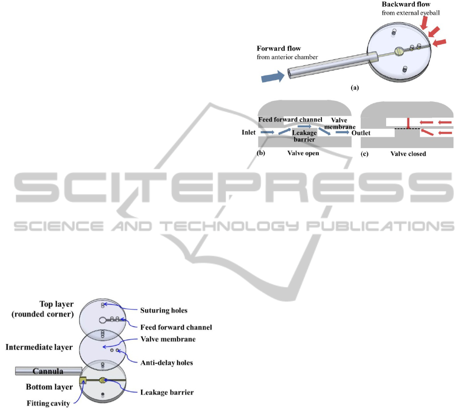
Figure 1 shows the configuration of the proposed
GDD with a leakage barrier and a valve membrane.
The GDD functionally comprises a silicone cannula
and a PDMS micro check valve. The PDMS valve
consists of s three layers. The top layer contains a
feedforward channel including a valve membrane to
prevent reverse flow from outside the eyeball. The
top and intermediate layers have several anti-delay
holes to reduce the pressure delay between the
feedforward channel and the fluidic channel. The
bottom layer comprises a fluidic channel and a
leakage barrier to maintain the appropriate cracking
pressure.
The base plate has a fitting cavity into which the
tip of the cannula is inserted. Suturing holes are
commonly formed onto all three layers to mount the
device on the eyeball for implantation.
Figure 1: Schematic of the glaucoma drainage device
(GDD) fabricated by the MEMS process.
3 OPERATION PRINCIPLE
Figure 2 shows the operation principle of the GDD
with a micro check valve that is normally closed.
When the intraocular pressure (P
i
) is higher than the
external pressure (P
e
) plus the cracking pressure (P
c
),
the valve membrane is deflected upward; therefore,
the aqueous humor generated from the anterior
chamber can flow out of the eyeball. When P
e
is
greater than or equal to the intraocular pressure (P
i
),
the membrane returns to its initial shape because the
feedforward channel is employed, preventing reverse
flow by compensating for the applied pressure of the
outlet channel.
Figure 2: Operation principle of the micro check valve for
regulating intraocular pressure: (a) bird's eye view, (b) the
check valve in open state, and (c) the check valve in closed
state. Dashed line represents the interface that makes
physical contact with no stiction.
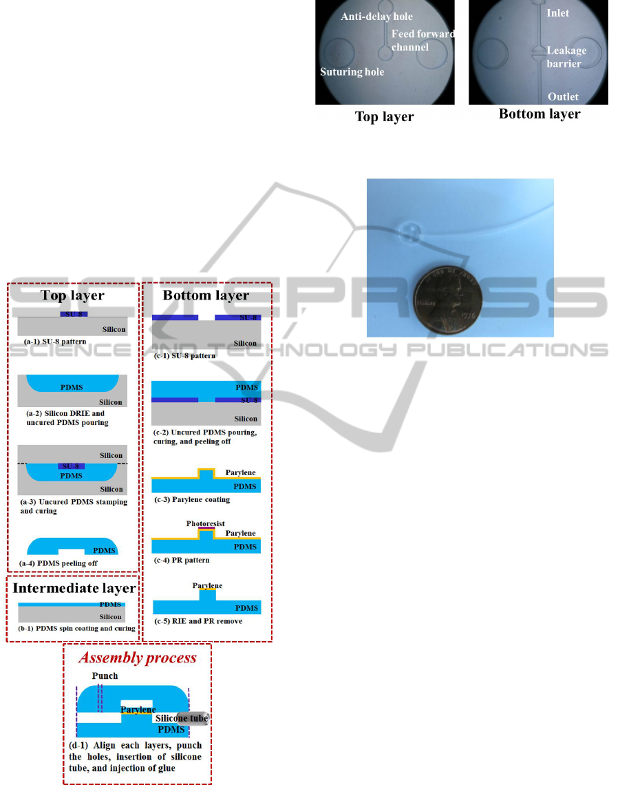
4 FABRICATION
Figure 3 shows the fabrication sequence of the
proposed GDD. First, a mold for the top layer was
fabricated using a negative photoresist (PR; SU-8).
The 100 μm-high SU-8 was patterned on a silicon
substrate. Second, another mold for rounding the
corners of the top layer was fabricated using an
isotropic process of deep reactive-ion etching
(DRIE). Third, the molds were aligned after pouring
uncured PDMS (Sylgard® 184, Dow Corning) on
the round mold. Fourth, the PDMS replica was
separated from the molds after curing at 60°C for 2
hours in a convection oven.
The intermediate layer, which is used to actuate
the valve, was fabricated by spin coating of uncured
PDMS on the glass, and it was cured under the same
conditions.
For the bottom layer, a PDMS replica was peeled
off of the patterned SU-8 mold. Next, parylene of 1
μm thickness was deposited onto the PDMS replica
of the bottom layer using LPCVD (PDS2010,
Specialty Coating Systems). Then, the PR was
selectively patterned on the parylene layer. After
selective etching of the parylene layer using reactive
ion etching (RIE), the PR was removed. Finally, the
PDMS bottom layer was dipped into acetone and
buffered hydrofluoric acid (BHF) to remove the
residual PR and silica-like layers, respectively
(Yinhua Lei et al., 2011).
The top and intermediate layers were bonded
PolymericMicroCheckValveforGlaucomaTreatment-ConsideringRateofAqueousHumorFormation
65
after treatment with O
2
plasma, and they were
punched for fabrication of the anti-delay hole using a
micro punch (Harris Uni-core). Then, the bottom
layer was assembled with the top and intermediate
layer after O
2
plasma treatment, and it was punched
to shape the main body and suturing holes. The
cannula (TYGON® S-54-HL Microbore tubing) was
inserted into the fluidic channel and fixed with
biocompatible bond (Henkel Loctite Corp.).
Microscopic images of the fabricated PDMS
replica of the top and bottom layers are shown in
figure 4.
Figure 5 shows a photo image of the fabricated
GDD whose diameter and thickness are 7.7 mm and
1 mm, respectively. The length of the cannula can be
individually adjusted considering the status of the
patient in surgery.
Figure 3: Fabrication sequences of glaucoma drainage
devices (GDD); (a) the top layer (cover), (b) the
intermediate layer (valve membrane), (c) the bottom layer
(base plate), and (d) the assembly process of the three
layers and cannula.
Figure 4: Microscopic images of the fabricated PDMS
replica of the top and bottom layers.
Figure 5: Image of the fabricated glaucoma drainage
device
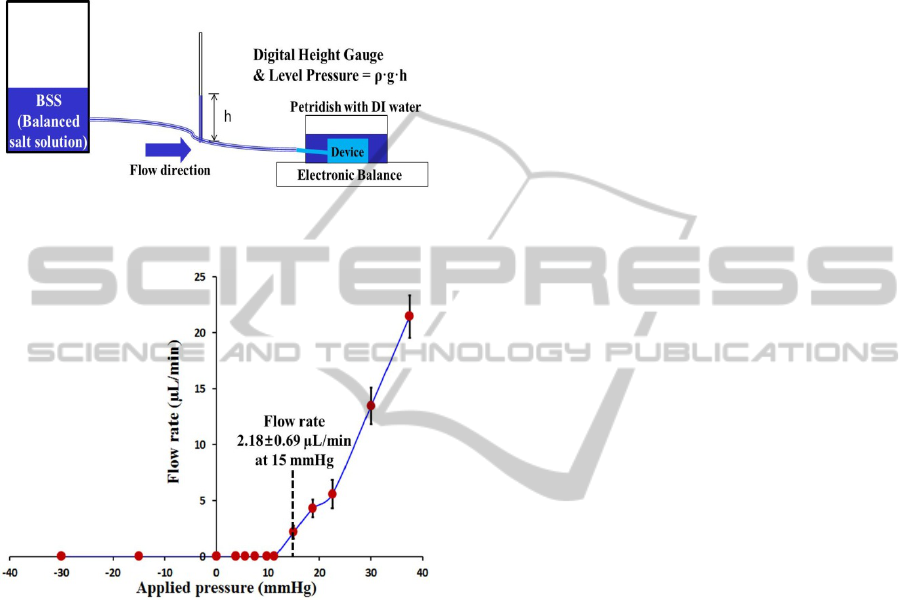
5 IN VITRO TEST
The flow characteristics of the micro check valve are
shown in figure 6. A balanced salt solution (BSS),
which has properties similar to those of the aqueous
humor, was used to measure the flow rate using an
electronic balance (AdventurerTM AR2140). Prior
to the application of hydrostatic pressure to the inlet
(cannula), the device was dipped into BSS to
maintain experimental conditions similar to those of
an in vivo experiment.
The membrane thickness of the device was 58
μm, and the diameter of valve membrane was 500
μm. Every data point of the fabricated GDD was
obtained three times at 3 min intervals for the
applied pressure.
Figure 7 shows the experimental flow rates of the
proposed GDD with respect to the applied pressure.
The results show that the flow rate is proportional to
the applied pressure when the applied pressure is
larger than the cracking pressure. The cracking
pressure was 15 mmHg, which lies within the
intraocular pressure range of normal patients (10 ~
20 mmHg). The mean value and standard deviation
of the flow rate were 2.18 ± 0.69 µL/min at cracking
pressure, which is large enough to cover the rate of
aqueous humor formation in a normal human eye
(1.5 ~ 3.4 µL/min). Meanwhile, reverse flow was not
BIODEVICES2013-InternationalConferenceonBiomedicalElectronicsandDevices
66
observed when hydrostatic pressure (up to 30 mmHg)
was applied to the outlet and the feedforward
channel. The in-vitro test results demonstrate that the
proposed GDD has high potential for the treatment
of glaucoma in view of cracking pressure, flow rate,
and the prevention of the unwanted reverse flow.
Figure 6: Illustration of experimental setup to measure the
flow rate of the fabricated GDD.
Figure 7: Flow rate of the proposed GDD (glaucoma
drainage device) with respect to applied pressure.
(thickness of valve membrane: 58 um, diameter of valve
membrane: 500 um; cracking pressure: 15 mmHg).
6 FURTHER WORKS
The fabricated glaucoma drainage device will be
mounted on a rabbit’s eye for further study.
Reliability testing (cracking pressure, flow rate, and
reverse flow) will be carried out, and inflammatory
reaction will be investigated through the in-vivo
animal test.
ACKNOWLEDGEMENTS
This research was supported by a grant from the
Institute of Medical System Engineering (iMSE) of
the Gwangju Institute of Science and Technology
(GIST), Republic of Korea.
REFERENCES
Brian A. Francis, Andres Cortes, Janet Chen, and Jorge A.
Alvarado, 1998. Opthalmology, 105(9); 1708-1714
Jeffrey Chun-Hui Lin, Feiqiao Yu, and Yu-Chong Tai,
2010. IEEE 23rd International Conference on Micro
Electro Mechanical Systems (MEMS), 1107 - 1110
Seunghwan Moon, Seongmin Im, Jaeyong An, Chang Ju
Park, Hwang Gyun Kim, Sang Woo Park, Hyoung Ihl
Kim, and Jong-Hyun Lee, 2012. Biomed Microdevices,
14; 325–335
P. Shuchi, R. P. Louis, 2010. Seminars in Ophthalmology,
25(5-6); 265–270
Yinhua Lei, Yaoping Liu, Wei Wang, Wengang Wu, and
Zhihong Li, 2011. Lab Chip, 11; 1385
PolymericMicroCheckValveforGlaucomaTreatment-ConsideringRateofAqueousHumorFormation
67
