
Photo-based Multimedia Applications using Image
Features Detection
Rui N
´
obrega and Nuno Correia
CITI, Departamento de Inform
´
atica, Faculdade de Ci
ˆ
encias e Tecnologia, Universidade Nova de Lisboa, Lisboa, Portugal
Keywords:
Computer Vision, Augmented Reality, Computer Graphics.
Abstract:
This paper proposes a framework for the creation of interactive multimedia applications that take advantage
of detected features from user-captured photos. The goal is to create games, architectural and space planning
applications that interact with visual elements in the images such as walls, floors and empty spaces. The frame-
work takes advantage of a semi-automatic algorithm to detect scene elements and camera parameters. Using
the detected features, virtual objects can be inserted in the scene. In this paper several example applications
are presented and discussed, and the reliability of the detection algorithm is compared with other systems. The
presented solution analyses the photos using graph-cuts for segmentation, vanishing point detection and line
analysis to detect the scene elements. The main advantage of the proposed framework is the semi-automatic
creation of the tri-dimensional model to be used in mixed reality applications. This enables scenarios where
the user can be responsible for the input scene without much prior knowledge or experience. The current
implemented examples include a furniture positioning system and a snake game with a user-built maze in the
real world. The proposed system is ideal for multimedia mobile applications where interaction is combined
with the back camera of the device.
1 INTRODUCTION
This paper presents a mixed reality system where vi-
sual features are acquired from user-captured photos
and used to create interactive applications. The main
motivation for this work is to create a framework that
enables the user to virtually reshape a photographed
scene. By adding virtual objects, changing colors
or changing lights the scene can be transformed into
something different. In this paper the main focus will
be given to the introduction of virtual objects that re-
act to the scene as if they had physical properties such
as mass or weight. The applications of this system
could be the creation of furniture testing simulations
in user spaces, virtual modifying of old photos, or
spatial-aware games.
The main problem presented in this paper is how
to acquire spatial features from a single image that
will allow the seamless embedding of virtual objects
in the scene for augmented reality (AR) applications.
A user with no special skills should be able to acquire
and manipulate the image in order to generate the in-
put for the given AR applications.
The expected contributions of this work are the
introduction of a semi-automatic method for high-
Figure 1: Augmented reality system, taking advantage of
visual high-level features detected from the image. The vir-
tual box is aligned with the world, and is laid on a virtual
plane that emulates the floor.
level feature extraction and several use-case proto-
types, which implement and make use of the given
features. The proposed use-case prototypes are: a
virtual reshaping tool (Figure 1) to contextually add
virtual objects in photos, and a virtual snake game
that uses a maze based in real world objects or shapes
(Figure 7).
The presented solution is based on an initial im-
age taken by the user. The image is analyzed to find
the floor, vanishing points and room orientation. The
augmented reality application introduces virtual ob-
298
Nóbrega R. and Correia N..
Photo-based Multimedia Applications using Image Features Detection.
DOI: 10.5220/0004244702980307
In Proceedings of the International Conference on Computer Graphics Theory and Applications and International Conference on Information
Visualization Theory and Applications (GRAPP-2013), pages 298-307
ISBN: 978-989-8565-46-4
Copyright
c
2013 SCITEPRESS (Science and Technology Publications, Lda.)

jects with a guideline and snapping system to assist
the user in the introduction of objects as seen in Fig-
ure 1.
2 BACKGROUND AND RELATED
WORK
Most augmented reality applications depend on some
form of computer vision technique (Forsyth and
Ponce, 2002; Szeliski, 2010) by recognizing marks or
using image tracking. Most AR applications (Tillon
and Marchal, 2011; Turcsanyi-Szabo and Simon,
2011) use real-time video from cameras, and then try
to superimpose virtual objects and animations. One
known example is the ARtoolkit
1
where virtual 3D
objects are introduced above predefined markers.
In this work, the main focus is given to sys-
tems that construct a model of the world and use the
same model to enhance the AR application (Wagner
et al., 2010; Yu and Malik, 2008). In the PTAM
project (Klein and Murray, 2007), a model of a small
workspace is instantly built by translating a camera
sideways. The model detects a plane where games
can be played.
Many techniques can be used to acquire features
for scene reconstruction. Our current approach is
based on extraction of features from a single image.
Currently some projects focus more on examining the
perspective knowing details such as vanishing lines
and a reference plane (Criminisi et al., 2000), oth-
ers analyse depth cues from the image and discover
3D by connecting small images planes (Saxena et al.,
2009). The analysis consists essentially of detecting
interesting properties from the image lines (Gupta,
2010; Gupta et al., 2011). The goal is to detect struc-
ture without the help of markers (Simon et al., 2000).
Using the detected features we intend to create AR
applications with new forms of interaction including
(Del Pero et al., 2011; Gupta et al., 2011; N
´
obrega
and Correia, 2012; Lai et al., 2011). Most of the pro-
cessing requires the analysis of the image in search
for main lines and vanishing points (Del Pero et al.,
2011; Lee et al., 2009; Rother, 2002; Yu and Malik,
2008). Several techniques have also been studied to
avoid clutter and noise (Hedau and Hoiem, 2009), re-
construct architectural environments (Pollefeys et al.,
2007; Rother, 2002) and automatically calibrate cam-
eras (Pollefeys et al., 1998).
Many systems use several images to reconstruct
the scene, namely stereo techniques (Sinha et al.,
2009), parallel images (Klein and Murray, 2007), sev-
1
ARtoolkit, http://www.hitl.washington.edu/artoolkit/.
eral photos (Debevec et al., 1996; Ishikawa et al.,
2011) or just plain video (Crandall et al., 2011; Polle-
feys et al., 2007) as in the structure from motion tech-
niques. Some systems rely on extra sensors or special
cameras such as depth cameras (Izadi et al., 2011) to
acquire additional information. Currently this work
focuses on cameras with no extra hardware, such as
the ones present on mobile devices or webcams.
Other systems rely on segmenting the scene into
super-pixels (Liu and Gould, 2010; Gould et al., 2009;
Kowdle et al., 2011) and infer the underlying model.
The Make3D (Saxena et al., 2009) project uses seg-
mentation to automatically create an explorable 3D
view from a picture or painting. In our work, seg-
mentation is used to detect the floor (Rother and Kol-
mogorov, 2004) with a human in the loop technique
(Kowdle et al., 2011). Some projects (Karsch et al.,
2011) use photo realistic rendering of synthetic ob-
jects on top of photographs using a human semi-
assisted model.
Different approaches include using Bayesian in-
ference (Furukawa et al., 2009), to detect scene orien-
tation. Some authors give more attention to scenes
with clutter (Hedau and Hoiem, 2009; Wang and
Gould, 2010), while others are more interested in real-
time applications (Klein and Murray, 2007; Wagner
et al., 2010). The main difference of our system is the
integration of single view techniques into a human as-
sisted mixed reality application.
3 CONCEPT OVERVIEW
With the advent of tablets and smartphones with
frontal and back cameras new opportunities arise for
multimedia applications that mix reality and virtual
content. Images and videos can be recorded instantly
and immediately used in the system or saved for later
interaction. Another obvious possibility is the real-
time interaction with the real world using the camera.
Figure 2: Handheld application using camera. The current
prototypes run in tablets and regular computers with web-
cams.
Using real video or captured images as input for
interactive mobile applications (Figure 2) presents
several challenges that need to be addressed.
Photo-basedMultimediaApplicationsusingImageFeaturesDetection
299

First of all, there is a factor of uncertainty related
with the user skill to capture good quality images.
There can be limitations related with the device cam-
era itself, as the image can be blurred and the scene
poorly illuminated. These are common problems in
all computer vision projects.
At the application level, users may have difficul-
ties in positioning or moving objects in a 3D space.
They may expect that the affordances of the real world
should apply to the virtual objects in the AR applica-
tion. As an example, virtual objects should collide
and be occluded by objects in the real world.
There are several properties that can be explored
in mixed reality in order to create rich multimedia
applications, such as: 3D structure, Segmentation,
Object detection and Tracking. Combining several
techniques is sometimes difficult due to increasing
processing cost (image processing is usually a heavy
task). The main goal of this work is to create a frame-
work that can be used to simplify the process of cre-
ating a multimedia application based on images cap-
tured by the user. Currently the main focus is on 3D
structure detection from a single image and segmen-
tation of user assigned areas.
4 PROBLEM FORMULATION
The fundamental concept for the proposed system is
the possibility of creating mixed and augmented real-
ity applications that take advantage of detected visual
features inside images of real world spaces. These
images are obtained with regular cameras with no ad-
ditional hardware.
The research problem being addressed here is how
to embed virtual objects inside an image in such a way
that the virtual objects react to physical concepts (i.e.,
gravity, obstacles) inside the virtual world. As seen in
the section 2, several previous studies (Karsch et al.,
2011) have found different answers to this problem.
The main problem can be divided into the follow-
ing different sub problems:
δ = f (I), (1)
φ = g(I, δ,C), and (2)
arApp(I,O,M) where M = {φ,δ,C} (3)
First (1) the input image I must be analyzed us-
ing f to search for low-level features δ such as edges,
straight lines or relevant points. Using δ, the im-
age I and the camera parameters C, the function g
(2) attempts to find high-level φ such as vanishing
points, horizon, room orientation or floor. The camera
parameters C and all the detected features and con-
strains, compose the virtual model M of the scene.
The final AR application (3) receives the model, the
virtual objects O and the input image I.
Our solution is based on the interpretation of the
main straight lines of the scene (Lee et al., 2009;
Rother, 2002) to find vanishing points (ϕ
1
) and scene
orientation (ϕ
2
) and segmentation techniques (Rother
and Kolmogorov, 2004) to find the floor (ϕ
3
). The
current model focuses mainly on these three high-
level features but can be easily extended to incorpo-
rate others (Simon, 2006) such as walls or plain sur-
faces. These features are primarily obtained trough
automatic analysis of the image ( f and g) but may
need to be refined through a human in the loop pro-
cess (Kowdle et al., 2011) where the user can give
simple hints to help the algorithm.
The image I is assumed to be an image of a Man-
hattan World scenario (Coughlan and Yuille, 1999;
Del Pero et al., 2011), where the floor is in the lower
part of the image and there is a large uncluttered space
in the room, where the virtual objects can be laid on.
The camera parameters C are assumed to be known,
and when they are not, they can sometimes be ex-
trapolated from the vanishing points, or several prior
models can be assumed (e.g., webcams).
5 ALGORITHM DETAILS
The implementation of our solution is summarized in
Figure 3 and the next subsections will detail the con-
struction of the augmented reality model M.
5.1 Input
The initial input of the problem is a raster image I
that meets the assumptions described in the previous
section. Additionally, the image should not be very
blurred and it should contain enough detail for feature
detection. In the current prototype, images can be ob-
tained through a webcam or by loading a file from the
disk. To help the user select a good picture the system
does a real-time analysis of the image to understand
if it has enough potential. To assess if the image is
complex enough for further analysis, FAST
2
feature
points and lines segments are extracted. For the image
to be accepted the amount of detected features must
be above a certain threshold value (dependent on the
resolution).
2
FAST in OpenCV, http://docs.opencv.org/modules/
features2d/doc/feature detection and description.html
GRAPP2013-InternationalConferenceonComputerGraphicsTheoryandApplications
300
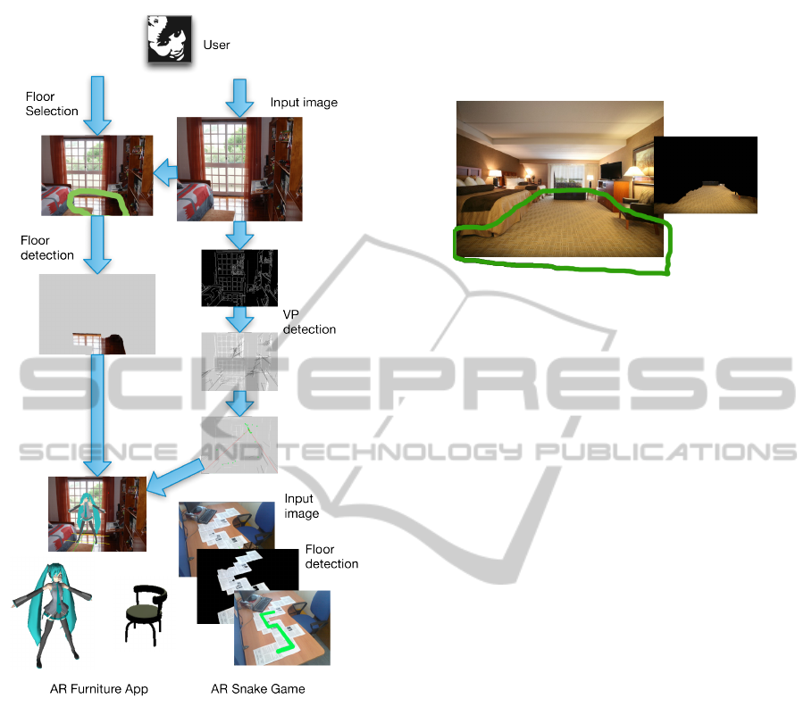
Figure 3: Steps involved in semi-automatic construction of
two Augmented Reality applications. The contribution of
the user consists in providing an input image and roughly
selecting the floor. The AR model is then automatically in-
ferred.
5.2 Region Segmentation
The detection of the scene floor (ϕ
3
) is necessary for
the AR application to understand where to place the
virtual object. In order to detect the floor the system
requires the assistance of the user. Using the input
image the user has to roughly sketch a line around
what she considers to be the floor as seen in Fig-
ure 4. More complex systems (i.e., statistical, prior
knowledge base inference) could be introduced to do
this step automatically, but for now the current system
does not focus on this topic.
The rough sketch is then used as input for an im-
plementation of the grabcut algorithm (Rother and
Kolmogorov, 2004) to define a mask m
3
, where for
each pixel it states if it belongs to the class floor or
not. This mask will later be important to verify colli-
sions with the floor.
Figure 4: Using the grabcut algorithm to extract the floor
mask (on the right). The user roughly sketches the green
line (best seen in color) around the floor and the algorithm
extracts the dominant floor pixels.
5.3 Vanishing Point Extraction
After acquiring the image and a estimate of where the
floor lays the scene must be analyzed in search for the
remaining features (ϕ
1
and ϕ
2
, as stated in g).
The vanishing points (ϕ
1
), are crucial to the aug-
mented reality system. Virtual objects must fade into
the same horizon as the scene. If at least two major
vanishing points are found, the field-of-view can be
extrapolated. The world orientation (ϕ
2
) of the scene
(more details on the next section) can be identified
and emulated.
Our algorithm for finding candidate vanishing
points (Lee et al., 2009; Rother, 2002) is briefly de-
scribed in the Algorithm 1 code block. It analyzes the
main lines containing the scene and tries to extrap-
olate the three most common line directions of the
scene, bearing in mind that parallel lines have com-
mon vanishing points. Figure 5 illustrates the current
algorithm. The main difference in our algorithm is
that we analyze the scene several times (e × h) with
different parameters, namely e different thresholds
and erode and dilate operations in the Canny filter,
and h different gap tolerances in the Hough transform
line detector. To be accurate the current used imple-
mentation of the Hough line detector returns line seg-
ments. The choice of the best set of parameters is
delayed until the last moment to evaluate through a
score function which one gives better results.
The score function helps to decide which param-
eters give a better, uncluttered view of the scene. To
calculate s, the first score, all lines are classified using
its slope as Horizontal (0
◦
± 5
◦
), Vertical (90
◦
± 5
◦
)
and Oblique (everything else). Considering only the
Oblique line segments, for each line the number of in-
tersections int(i) with other line segments is counted.
Photo-basedMultimediaApplicationsusingImageFeaturesDetection
301

Algorithm 1: Generating Candidate Vanishing Points.
L e t I be t h e i n p u t i mage
L e t E[e] be t h e v e c t o r o f e image s
c o n t a i n i n g Canny e d g e s o f t h e
s c e n e w i t h d i f f e r e n t t h r e s h o l d s .
L e t L[e][h] be t h e v e c t o r o f e × h l i n e
s e t s c o n t a i n i n g d i f f e r e n t
d e t e c t e d l i n e s f o r e ac h E[i] .
L e t S ←
/
0 be t h e s c o r e o f t h e l i n e
s e t .
L e t S
0
←
/
0 be t h e r e f e r e n c e t o t h e
l i n e s e t .
f o r i = 1 u n t i l e
E [ i ] ← ca nny(I,cannyParam
i
)
f o r j = 1 u n t i l h
L[i][ j] ←Ho ugh Lin es(I,lineParam
j
)
s← s c o r e (L[i][ j]) , t e s t s i f h a s
en ough i n f o r m a t i o n o r
e x c e s s i v e c l u t t e r .
i f s > S t h e n S ← s and S ’← L[i][ j]
e n d i f
e n d f o r
e n d f o r
L e t (l
i
,l
j
) ∈ S
0
L e t V ← be t h e s e t o f l i n e
i n t e r s e c t i o n s .
f o r some r a n d p a i r o f l i n e s e g m e n t s
(l
i
,l
j
) (RANSAC)
t
i j
← i n t e r s e c t i o n of (l
i
,l
j
) .
i f c o n s t r a i n s (t
i j
) = 1 t h e n
add i n t e r s e c t i o n t o V
e n d i f
e n d f o r
v ← c l u s t e r i n g (V ) , v e r i f y
wh er e a r e t h e
most p r e d o m i n a n t i n t e r s e c t i o n s
a c c o r d i n g t o x , y and k
r e t u r n v , v e c t o r w i t h 1 t o 3 p o i n t s
Line segments with a large number of intersections
are considered clutter and have a lower weight in s,
longer line segments give an extra weigh w(i) to
n
∑
i
w(i)
int(i) + 1
(4)
Having chosen the line set with better s score, the
same line set is analyzed for intersections between
the lines. For efficiency reasons only some pairs
of lines are tested using Random Sample Consen-
sus (RANSAC). Each intersection t
i j
is tested against
several constraints, namely the intersection should be
outside the two line segments and the line segments
should have a slope difference larger than 10 degrees.
In the end, there should be a large number of two-
dimensional points populating the scene. The three
vanishing points are extracted using a nearest neigh-
Figure 5: Vanishing Point analysis for Figure 4. On the
top right: Canny filter analysis. Bottom right: detected line
segments, oblique lines are in black. Left: main line inter-
section points in green and main vanishing point detected
using clustering nearest neighbors.
bors approach to cluster the most common groups of
points as seen in Figure 6. Each group must have a
minimum number of points for the vanishing point to
be considered. The vanishing point is the average po-
sition of the cluster points. Sometimes it may not be
possible to find the three dominant vanishing points.
If no vanishing point is found the algorithm tries the
next line set from L with better score s.
5.4 3D World Orientation
The real world orientation (ϕ
2
) depends on the direc-
tion in which the picture was taken. Currently we are
considering that the Y axis (vertical) is fixed and the
X and Z are free. The goal is to find the X and Z ori-
entation of the scene in the photo. Most Manhattan
world indoor scenes have parallel walls, the ceiling is
usually parallel to the ground and corners are usually
intersections of perpendicular planes.
Knowing the main vanishing points allows rotat-
ing the 3D virtual camera model in order to be aligned
with the real world point of view. This means that
when the depth of an object increases it will fade not
to the center but to the direction of the vanishing point
that corresponds to the Z axis. Furthermore objects
should look like they are parallel to the elements in
the scene (i.e., walls). Using the main vanishing point
(the one with a larger point cloud) the virtual world
is rotated in two axis to align the objects with the
scene. The rotations depend on the fiel-of-view (fov)
and on the main vanishing point vp. roty is the rota-
tion around the Y axis and rotx is the same around the
X axis.
δ = tan(π · f ov/360) (5)
di f f
x
= vp
x
− middle
x
,di f f
y
= vp
y
− middle
y
(6)
rot
y
= arctan(di f f
x
· δ/middle
x
) (7)
rot
x
= arctan(di f f
y
· δ/middle
y
) (8)
The above are only valid for small rotations (<∼
45 degrees) because for larger values the distortion is
GRAPP2013-InternationalConferenceonComputerGraphicsTheoryandApplications
302

too large. The detection of the scene orientation (ϕ
2
)
is dependent on the success of the algorithm to detect
ϕ
1
. Additionally, the virtual floor (ϕ
3
) is assigned to
be a plane in the world with a predefined negative y
coordinate. This value is defined considering the av-
erage height that people take photos, but can later be
changed by the user in the AR tool.
6 MIXED REALITY SYSTEM
The augmented reality (AR) framework takes into
consideration the detected features vanishing points
(ϕ
1
), scene orientation (ϕ
2
) and floor (ϕ
3
). The cur-
rent prototypes explore several possibilities that can
be achieved in AR applications using CV high-level
features.
Using the 3D oriented model M (introduced in
section 4) it is possible to define a virtual floor where
users can lay 3D meshes. The users just have to push
the objects back and forth, or left and right, in a 2D
model that allows this freedom. This is an important
feature since not all users have the skills to correctly
visualize and place an object in a 3D world. Reliev-
ing the user from having to match the object with the
floor and from having to orient the object to match the
direction of the walls helps in the process. Figures 3
and 6 are examples of the 3D oriented world model
with superimposed 3D objects that represent virtual
furniture.
The introduction of virtual content should be done
seamlessly, and the user should not be aware of all
the processing that is involved in the application. In
the user perspective, the interface should be effective,
with some simple instruction hints. The objects and
drawings should be placed with the correct perspec-
tive.
6.1 Implementation Details
The current framework, prototypes, examples and ex-
periences were tested in a dual-core 2.53GHz com-
puter with 4GB of RAM. Some usability tests pre-
sented in section 7 were conducted in a tablet with
a single 1.33GHz processor with 4GB of RAM. All
webcams were used with a resolution of 640 by 480
pixels. Imported photos had different resolutions with
a minimum of 640 by 480.
The system is currently implemented in C++. The
algorithms takes advantage of the OpenCV
3
library,
especially the data types, the Hough-transform imple-
mentation, several image filters and image descrip-
3
OpenCV, http://opencv.willowgarage.com
tors. The interface and image/camera input is sup-
ported by the openFrameworks
4
library.
6.2 Virtually Reshape a Room
One application for the detected features is a furniture
testing system where users can photograph the place
where they wish to add the piece and test virtually
if the object fits and looks pleasant in that spot. One
hypothesis, emulated by the current prototype (Figure
6), is to create guidelines around the virtual objects
indicating if the object is placed on the floor or if it is
aligned with the scene. A snapping system helps the
user to ease the task of placing objects in the correct
position.
The current guidelines are created taking into ac-
count the detected features ϕ . The snapping to the
floor guideline, seen in yellow in Figure 6, is shown
when the object reaches the invisible plane represent-
ing the ground (see subsection 5.4). Additionally the
object can be tested to verify if it is inside the floor
area or above scene objects. Using the previously cal-
culated floor mask m
3
(see subsection 5.2) it is possi-
ble to test if the object is really on the ground. Know-
ing the current projection matrix (Szeliski, 2010) P,
the Model View matrix V and the w coordinates of
the object (w = (x,y,z,1)) it is possible through
w
0
= PV w (9)
to obtain w
0
, the screen coordinates of the ob-
ject. Testing if the point belongs to the floor mask (if
m
3
(w
0
) is positive) gives the information about the ob-
ject being in the floor or in the rest of the scene. This
technique can be used in different ways. The virtual
objects can collide with the walls, floor and scene ob-
jects or can snap to the limits of the floor. The current
prototype does not deal with occluded floors.
Figure 6: Example of the introduction of virtual objects that
are aligned with the scene and snapped to the floor.(best
seen in color)
The other implemented guideline appears when
the object has the same orientation as the other main
4
OpenFrameworks, http://www.openframeworks.cc/
Photo-basedMultimediaApplicationsusingImageFeaturesDetection
303
scene components. This guideline takes advantage
of the scene orientation (ϕ
2
) feature and is shown in
green in Figure 6. This could be an important feature
in applications, since virtual objects can be presented
as if parallel to the wall and scene objects, helping the
immersion of the user and facilitating the positioning
of the object in the scene.
6.3 Snake in Real-world Maze
Although conceptually simple the three detected fea-
tures (ϕ
1
, ϕ
2
and ϕ
3
) can be combined to recreate
several well known applications, but with interaction
with the real-world. The snake game is a well known
computer game, in this game, a snake travels through
a maze with obstacles and walls. The goal is to never
hit a wall or obstacle and survive as much time as pos-
sible. Usually there are bonus objects to catch which
make the player earn points but have the side effect
of increasing the size of the snake and/or speeding up
the game.
In order to showcase the detected features, a
proof-of-concept application was created: a snake
game based in a user image. It is a 3D snake game
where the user creates the maze in the real world. The
maze can be made of any material; it only needs to be
sufficiently different from the background.
To prepare the game, the player should create a
maze in an empty plane (e.g.,floor or table). To take
advantage of scene orientation (ϕ
2
), the objects com-
posing the maze should be orthogonal as in a Manhat-
tan world the detection is improved. The user takes
a picture of the scene from the desired position and
roughly sketches the floor as seen in Figure 7. This
will be used to detect the floor (ϕ
3
) of the maze. This
process was already described in subsection 5.2.
The image is then analyzed to find the main van-
ishing points (ϕ
1
) and scene orientation (ϕ
2
). Cur-
rently, there is a previous step of scale adjustment of
the snake, but that could be, in the future, inferred by
the size of the maze.
Finally the snake is positioned on the virtual plane
and reacts to the detected floor (the maze in this con-
text) as seen in Figure 7. The player looses when the
snake leaves the maze. In this system the coordinates
of the head of the snake are constantly being trans-
formed using Equation 9 and tested against the mask
m
3
of the detected floor. With this simple game the
user has the possibility to instantly change the level
in a very tangible and direct form. As mentioned,
any place can be used as scenario for the gameplay.
Social interactions can arise where one user creates
the labyrinth and other tries to complete it or survive
a certain amount of time in it. Games can be played
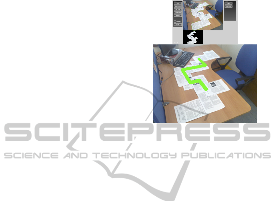
Figure 7: Real world maze, made from sheets of papers.
Maze selection, based on the floor selection presented in
subsection 5.1.Using the room orientation and the mask m
of the floor, a virtual snake travels through the paper maze.
with improbable scenarios such as monuments, casual
areas or intimate places.
6.4 Other Possible Applications
The current prototypes implement the features de-
scribed in the previous section. The goal is to con-
struct a generic framework, with these and other fea-
tures, so that different augmented reality applications
can be explored. Examples include games that can
be played in 3D in a user-designated scenario, space
sharing and editing between known users or virtually
reshaping a room with virtual objects.
7 EXPERIMENTS AND RESULTS
The current system extracts several features from an
input image and presents an augmented reality in-
terface based on the same features. Several tests
(N
´
obrega and Correia, 2012) have been made to as-
sess the effectiveness of the used detection algo-
rithms.
The detection of the floor mask m produces good
results on most surfaces and images. Failures are
usually related with low contrast images and non-
Lambertian surfaces with high reflectance.
The detection of the vanishing points show a high-
degree of success in Manhattan (Coughlan and Yuille,
1999) scenes.In order to assess the reliability of the
vanishing point detection presented in subsection 5.3,
GRAPP2013-InternationalConferenceonComputerGraphicsTheoryandApplications
304
the algorithm was tested with several images from dif-
ferent datasets. The system relies on the visual infor-
mation available in each image, especially orthogonal
lines. Other factors must be taken in consideration,
such as image clutter, misleading lines and blurred
images. Note that since the goal is to use this system
in a interactive multimedia system, processing times
should be kept as low as possible.
To evaluate the detection system, a large amount
of images were collected and tested. For each image
the two major vanishing points were annotated and
the processing time registered. Next a visual appli-
cation was created to evaluate the results and its cor-
rectness. The application seen in Figure 8, presents
sequentially all the images from the dataset with three
lines. The red line represents the most probable van-
ishing point detected. This will be the main vanishing
point used to signal the scene and virtual objects ori-
entation. The green line represents the second most
probable vanishing point. The blue (horizontal) line
represents the horizon line of the scene. Depending
on the confidence level of the detection, the system
may only present some lines and in worst-case sce-
nario none. The goal of this application is to have a
user that manually analyses each image and classifies
each image as Correctly detected or Incorrectly de-
tected. The operation is quickly achieved with two
keyboard keys.
The algorithm was tested in four different
datasets, each with its own characteristics:
• General: mixed collection of photos used to test
the algorithm, that includes indoor and outdoor
photos, old, blurred and pixelated images.
• Lab: photos from the interior of a building and a
university campus.
• Flickr-Mix: Mix of photos obtained from Flickr
5
with keywords such as House, House Interior and
Buildings. It includes some landscape images
with nature.
• YorkUrbanDB: The York Urban Line Segment
Database
6
is an online database used by Cough-
lan and Yuille (Coughlan and Yuille, 1999), which
contains images of urban environments consisting
mostly of scenes from the campus of York Uni-
versity and downtown Toronto, Canada. Most im-
ages follow the rule of the Manhattan world.
The results from the classification using the appli-
cation presented in Figure 8 can be seen in Table 1
and Figure 9.
5
Flickr, http://www.flickr.com/.
6
York Urban DB, http://www.elderlab.yorku.ca/
YorkUrbanDB/.
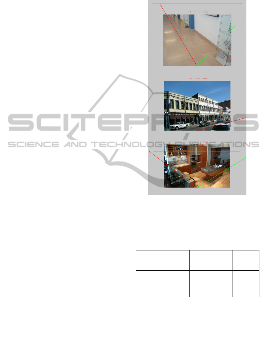
Figure 8: The system automatically detected the most prob-
able main vanishing point (red line) and the second most
probable (green line). The blue line represents the detected
horizon line. The above images are screenshots of the man-
ual application used to verify the correctness of the auto-
matic detection algorithm.
Table 1: Scene Orientation and Detection Data and Compu-
tational Processing Times.
Photos Total
Time
(s)
Avg.
Time
(s)
Success.
Detec-
tions
General 53 59.47 1.12 43
Lab 35 54.87 1.57 30
Flickr-Mix 317 908.4 2.87 182
YorkU.DB 102 190.58 1.87 81
The results show a high reliability of the algorithm
with most datasets having a success rate around
80% (average combined success 66.27%). The sys-
tem worked better with Manhattan scenes, especially
house interiors. Outdoor images of city buildings also
perform well. This is the reason for the good results in
the Lab and YorkUrbanDB datasets. The Flickr-Mix
was not so successful mostly due to problems related
Photo-basedMultimediaApplicationsusingImageFeaturesDetection
305
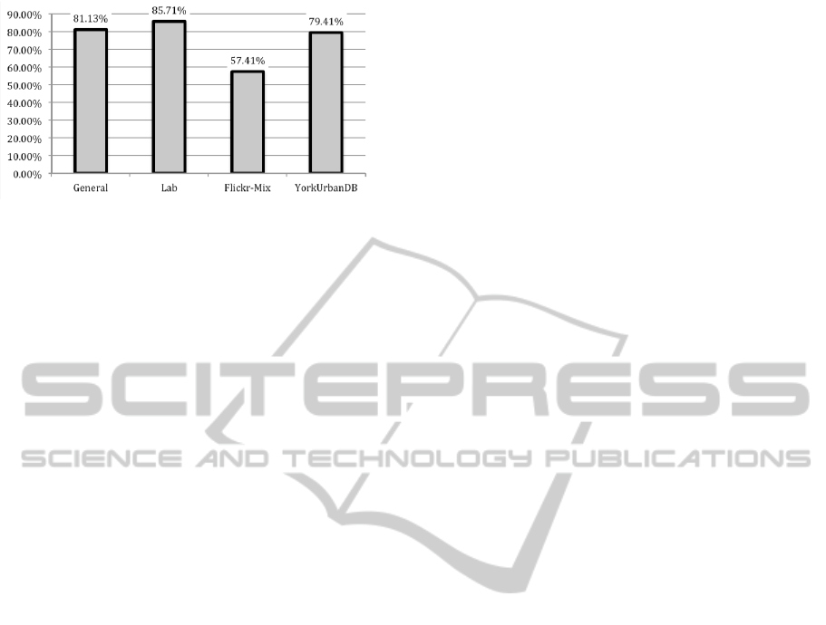
Figure 9: Success rate for each dataset.
with outdoor nature such as trees, landscapes, and
modern and unconventional architecture. The Gen-
eral dataset had images of lobbies, floors, tables and
spaces suitable for the presented AR prototypes, and
it also had a higher rate.
These results show that, although not 100% re-
liable in all situations, the current algorithm works
in enough situations to be useful in a mixed reality
interactive system. In a multimedia application, the
user can be instructed to take pictures of places with
enough line information or systems, as the one pre-
sented in subsection 5.1, can be used to increase the
success rate of the detection. Additionally, since the
processing time is under 3 seconds, the user can al-
ways take or use another picture if the first one was
not correct.
8 CONCLUSIONS AND FUTURE
DIRECTIONS
This paper introduces a new approach to the use of re-
constructed models from single images in AR appli-
cations. The main contributions are a feature detect-
ing system and an AR interface where virtual objects
react to the scene. To validate the ideas proposed in
the framework, two working prototypes are presented
taking full advantage of the discussed high-level fea-
tures. The first represents a multimedia application
where virtual furniture and interesting objects could
be used in the context of a house interior. The second
is an application that makes use of ordinary physical
objects to create the different game-levels of the vir-
tual game. These are some of the possibilities that can
be achieved with this system.
In the future, additional features could be pursued
to enhance the applications. The vanishing points
and horizon detection can also benefit greatly from
the use of accelerometers to detect the direction of
the floor, although this limits the system to devices
that have these technologies (excluding, for example,
most laptops and desktops). Our goal is to further
explore these prototypes and develop better user in-
terfaces to fully explore all the possible interactions
and enhance the quality of the experience. We are
also planning to release the software as open source
so that other developers could create more complex
applications such as games and photo-editing applica-
tions used seamlessly in devices with a camera. This
could provide valuable insights about the current ver-
sion of the framework and the path that should be fol-
lowed regarding future developments.
ACKNOWLEDGEMENTS
This work was funded by FCT/MEC, through grant
SFRH/BD/47511/2008, and CITI/FCT/UNL through
grant PEst- OE/EEI/UI0527/2011.
REFERENCES
Coughlan, J. J. M. and Yuille, A. L. A. (1999). Manhat-
tan World : Compass Direction from a Single Image
by Bayesian Inference. In Proceedings of the Inter-
national Conference on Computer Vision- Volume 2
(ICCV ’99), volume 2, pages 1–10. IEEE Computer
Society.
Crandall, D., Owens, A., Snavely, N., and Huttenlocher, D.
(2011). Discrete-continuous optimization for large-
scale structure from motion. In Computer Vision and
Pattern Recognition (CVPR’11), 2011 IEEE Confer-
ence on, pages 3001–3008. IEEE Computer Society.
Criminisi, A., Reid, I., and Zisserman, A. (2000). Single
View Metrology. International Journal of Computer
Vision, 40(2):123–148.
Debevec, P. E., Taylor, C. J., and Malik, J. (1996). Mod-
eling and Rendering Architecture from Photographs
: A hybrid geometry- and image-based approach.
In Proceedings of the 23rd annual conference on
Computer graphics and interactive techniques (SIG-
GRAPH ’96), pages 11–20. ACM.
Del Pero, L., Guan, J., Brau, E., Schlecht, J., and Barnard,
K. (2011). Sampling bedrooms. In Computer Vision
and Pattern Recognition (CVPR’11), 2011 IEEE Con-
ference on, pages 2009–2016. IEEE Computer Soci-
ety.
Forsyth, D. A. and Ponce, J. (2002). Computer Vision: A
Modern Approach, volume 54. Prentice Hall.
Furukawa, Y., Curless, B., Seitz, S. M., and Szeliski, R.
(2009). Manhattan-world stereo. In Computer Vision
and Pattern Recognition (CVPR’09), 2009 IEEE Con-
ference on, volume 0, pages 1422–1429. IEEE Com-
puter Society.
Gould, S., Fulton, R., and Koller, D. (2009). Decompos-
ing a Scene into Geometric and Semantically Consis-
tent Regions. In Computer Vision, 2009 IEEE 12th
International Conference on (ICCV’09), number Iccv,
pages 1–8. IEEE Computer Society.
GRAPP2013-InternationalConferenceonComputerGraphicsTheoryandApplications
306

Gupta, A. (2010). Blocks world revisited: Image under-
standing using qualitative geometry and mechanics.
Computer VisionECCV 2010, 125(1-2):482–496.
Gupta, A., Satkin, S., Efros, A. a., and Hebert, M. (2011).
From 3D scene geometry to human workspace. In
Computer Vision and Pattern Recognition (CVPR’11),
2011 IEEE Conference on, pages 1961–1968. IEEE
Computer Society.
Hedau, V. and Hoiem, D. (2009). Recovering the spatial
layout of cluttered rooms. In Computer Vision, 2009
IEEE 12th International Conference on (ICCV’09).
IEEE Computer Society.
Ishikawa, T., Thangamani, K., Kourogi, M., Gee, A. P.,
Mayol-Cuevas, W., Hyun, J., and Kurata, T. (2011).
Interactive 3-D indoor modeler for virtualizing service
fields. Virtual Reality.
Izadi, S., Newcombe, R. A., Kim, D., Hilliges, O.,
Molyneaux, D., Hodges, S., Kohli, P., Shotton, J.,
Davison, A. J., and Fitzgibbon, A. (2011). Kinect-
Fusion: real-time dynamic 3D surface reconstruction
and interaction. In ACM SIGGRAPH 2011 Talks,
UIST ’11, page 23. ACM, ACM.
Karsch, K., Hedau, V., and Forsyth, D. (2011). Render-
ing synthetic objects into legacy photographs. ACM
Trans. Graph, 30(6):1–12.
Klein, G. and Murray, D. (2007). Parallel Tracking and
Mapping for Small AR Workspaces. 2007 6th IEEE
and ACM International Symposium on Mixed and
Augmented Reality, 07:1–10.
Kowdle, A., Chang, Y., and Gallagher, A. (2011). Active
Learning for Piecewise Planar 3D Reconstruction. In
Computer Vision and Pattern Recognition (CVPR’11),
2011 IEEE Conference on, pages 24–26. IEEE Com-
puter Society.
Lai, J., Chen, C., Wu, P., and Kao, C. (2011). Tennis real
play: an interactive tennis game with models from real
videos. In Proceedings of the 19th ACM international
conference on Multimedia - MM ’11, volume 3, pages
483–492.
Lee, D. C., Hebert, M., and Kanade, T. (2009). Geomet-
ric reasoning for single image structure recovery. In
Computer Vision and Pattern Recognition (CVPR’09),
2009 IEEE Conference on, volume 0, pages 2136–
2143. IEEE Computer Society.
Liu, B. and Gould, S. (2010). Single image depth estima-
tion from predicted semantic labels. In Computer Vi-
sion and Pattern Recognition (CVPR’10), 2010 IEEE
Conference on. IEEE Computer Society.
N
´
obrega, R. and Correia, N. (2012). Magnetic augmented
reality: virtual objects in your space. In Proceeding
of the 2012 International Working Conference on Ad-
vanced Visual Interfaces (AVI’12), pages 3–6. ACM.
Pollefeys, M., Koch, R., and Gool, L. V. (1998). Self-
calibration and metric reconstruction in spite of vary-
ing and unknown internal camera parameters. Com-
puter Vision and Pattern Recognition (CVPR’98),
1998 IEEE Conference on, pages 90–95.
Pollefeys, M., Nist
´
er, D., Frahm, J. M., Akbarzadeh, A.,
Mordohai, P., Clipp, B., Engels, C., Gallup, D., Kim,
S. J., Merrell, P., Salmi, C., Sinha, S., Talton, B.,
Wang, L., Yang, Q., Stew
´
enius, H., Yang, R., Welch,
G., and Towles, H. (2007). Detailed Real-Time Urban
3D Reconstruction from Video. International Journal
of Computer Vision, 78(2-3):143–167.
Rother, C. (2002). A new Approach to Vanishing Point De-
tection in Architectural Environments. Elsevier, (Jan-
uary 2002):1–17.
Rother, C. and Kolmogorov, V. (2004). GrabCut Interac-
tive Foreground Extraction using Iterated Graph Cuts.
ACM Transactions on Graphics (TOG).
Saxena, A., Sun, M., and Ng, A. Y. (2009). Make3D: Learn-
ing 3D Scene Structure from a Single Still Image.
IEEE Transactions on Pattern Analysis and Machine
Intelligence, 31(5):824–40.
Simon, G. (2006). Automatic online walls detection for im-
mediate use in AR tasks. In Mixed and Augmented
Reality, 2006. ISMAR 2006., pages 4–7. IEEE Com-
puter Society.
Simon, G., Fitzgibbon, A. W., and Zisserman, A. (2000).
Markerless tracking using planar structures in the
scene. Proceedings IEEE and ACM International
Symposium on Augmented Reality ISAR 2000, 9:120–
128.
Sinha, S. N., Steedly, D., and Szeliski, R. (2009). Piece-
wise planar stereo for image-based rendering. 2009
IEEE 12th International Conference on Computer Vi-
sion, (Iccv):1881–1888.
Szeliski, R. (2010). Computer vision: algorithms and ap-
plications. Springer.
Tillon, A. and Marchal, I. (2011). Mobile augmented re-
ality in the museum: Can a lace-like technology take
you closer to works of art? In Mixed and Augmented
Reality - Arts, Media, and Humanities (ISMAR-AMH),
2011 IEEE International Symposium On, number Fig-
ure 1, pages 41–47. IEEE Computer Society.
Turcsanyi-Szabo, M. and Simon, P. (2011). Augmenting
Experiences Bridge Between Two Universities. In
Augmented Reality (ISMAR), 2011, pages 7–13.
Wagner, D., Reitmayr, G., Mulloni, A., Drummond, T.,
and Schmalstieg, D. (2010). Real-time detection
and tracking for augmented reality on mobile phones.
IEEE Transactions on Visualization and Computer
Graphics, 16(3):355–368.
Wang, H. and Gould, S. (2010). Discriminative Learning
with Latent Variables for Cluttered Indoor Scene Un-
derstanding. In Proceedings of the 11th European
conference on Computer vision: Part IV (ECCV’10),
pages 497–510. Springer-Verlag.
Yu, S. X. and Malik, J. (2008). Inferring spatial layout
from a single image via depth-ordered grouping. 2008
IEEE Computer Society Conference on Computer Vi-
sion and Pattern Recognition Workshops, pages 1–7.
Photo-basedMultimediaApplicationsusingImageFeaturesDetection
307
