
Comparison of Energy Harvesting Techniques for Wearable Activity
Monitoring Devices
Ana Cimpian
1
, Bastien Granier
2
, Gearóid Ó Laighin
1
and Maeve Duffy
2
¹Bioelectronics Research Cluster, Electrical & Electronic Engineering, National University of Ireland, Galway, Ireland
²Power Electronics Research Centre, Electrical & Electronic Engineering, National University of Ireland, Galway, Ireland
Keywords: Energy Harvesting, Electromagnetic, Piezoelectric, Self- sustained System, Activity Monitoring Devices.
Abstract: Piezoelectric and electromagnetic generation are the two most commonly used energy harvesting
techniques. The aim of this paper is to compare the two techniques in terms of their potential for powering a
wearable monitoring device. An electromagnetic generator and a piezoelectric system are proposed to
power an activity monitoring device located in the shoe. Results to date indicate that the electromagnetic
generator produces the best output power levels.
1 INTRODUCTION
Energy harvesting is a research field that has
become of more interest with the growth in
popularity of portable electronic devices and their
increased power requirements. Even though there
have been several studies comparing different
energy harvesting techniques (Mateu, 2005) and
(Paulo, 2010), very little has been done to compare
techniques for a given application.
This work focuses on harvesting energy from the
human body during normal everyday activities, for
powering wearable electronic applications. The aim
of this work is to propose a self- sustained activity-
monitoring device destined for every day monitoring
of elderly people. This will include comparing the
performance of two generators supplying power to a
pedometer system, where the generators are based
on the most commonly applied energy harvesting
techniques: electromagnetic and piezoelectric
A growing trend has been observed in the
development of activity monitoring devices: e.g. like
FitBit (Fitbit, US), Nike sensors (Nike, Inc., US) and
the Shimmer (Shimmer Research, Ireland). These
are most commonly used in monitoring sports
activities in order to increase performance.
Lately, such monitoring devices have also been
employed in health care, for monitoring the mobility
and activity levels of elderly people. Clearly, for
such devices to be worn or attached to the body, the
most important characteristics are small size,
usability and the ability to give real time information
with a reliable, low maintainence power source.
With a view to improving the rate of use by elderly
people, the possibility of harvesting energy
expended in activity to produce a self-sustained
pedometer is proposed, thereby removing the need
for users to recharge batteries.
2 ACTIVITY MONITORING
DEVICES
Typical power consumptions values for some of the
commonly applied components in activity
monitoring devices are compared in Table 1.
Table 1: Typical power consumption levels for devices
employed in activity monitoring.
Device Power consumption (mW)
Accelerometers 0.16
Low power processors 0.93- 1.4
Other sensors 0.16- 11.6
LEDs 100
Bluetooth
Sleep mode 2
During transmission 24
Considering that the power consumption of
individual circuit blocks varies significantly between
sleep and active modes, the design of a generator
that produces pulses of power was considered a
simpler and more achievable target. The system will
contain an nRF chip that will transmit a pulse of data
273
Cimpian A., Granier B., Ó Laighin G. and Duffy M..
Comparison of Energy Harvesting Techniques for Wearable Activity Monitoring Devices .
DOI: 10.5220/0004252102730277
In Proceedings of the International Conference on Biomedical Electronics and Devices (BIODEVICES-2013), pages 273-277
ISBN: 978-989-8565-34-1
Copyright
c
2013 SCITEPRESS (Science and Technology Publications, Lda.)
every time a step is taken, thus providing a self-
sustained pedometer. The selected chip for this
application is the nRF24AP2-1CH (Nordic
Semiconductor, Norway) and it operates on voltages
between 1.9V and 3.6V and power levels between
0.040 and 60 mW. Typical current consumption for
tasks performed by the device are displayed in Table
2.
Table 2: Current requirements of the nRF chip.
Activity Current requirements
Sleep mode 500 nA
Broadcast 14-42 uA
Acknowledging a package 18- 52 uA
Active mode 17mA
3 WEARABLE GENERATOR
3.1 Electromagnetic Generator Design
Electromagnetic power generation is a widely used
technique in portable applications like those
presented by (Sodano, 2005) and (Arnold, 2007).
Although different materials and techniques have
been suggested, the main drawback of
electromagnetic generators is that they have
considerable dimensions.
The generator proposed in this paper is based on
on the sliding magnet principle described in (Carroll,
2011). Based on the theory that as long as the mass
of the magnet is considerably smaller than the mass
of the foot continuous movement of the magnet can
be sustained by external forces due the movement of
the foot, no additional or deliberate effort from the
user is needed.
The prototype generator was assigned a volume
of 50x15x15 mm
3
and disk shaped NdFeB magnets
with diameters of 10mm were determined to be
optimum for the generator cross sector. Applying
optimization rules, it was determined that the most
suitable generator prototype consists of 1 coil, with
an optimum coil length of 17.3 mm centred along
the 50 mm generator length. The copper wire used
has a diameter of 0.22 mm, this leading to the main
coil having 300 turns disposed in three layers in
order to fit the allocated space and resulting an
internal coil DC resistance of 6 Ω.
In order to maximise the power output of the
generator, but still maintain its size in the allocated
volume, two additional half coils have been
considered in the remaining generator length at
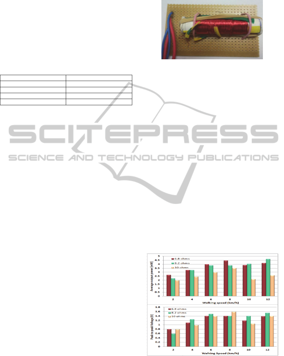
either end of the main coil. A prototype of the
electromagnetic generator is shown in Figure 1.
Figure 1: Electromagnetic generator prototype.
Open circuit AC measurements were undertaken
for a set of pre-established walking speeds. The
generator produces voltages between 0.5 V peak for
a walking speed of 2km/h (representing very slow
walking), and 2.6 V peak for 12 km/h (representing
running).
Through a set of AC measurements, it was
determined that the location for the generator
preferred for both performance and ease of wear, is
on the exterior side of the foot at the heel area. The
same walking speeds as in the case of open circuit
tests were applied with a series of load resistances
attached.
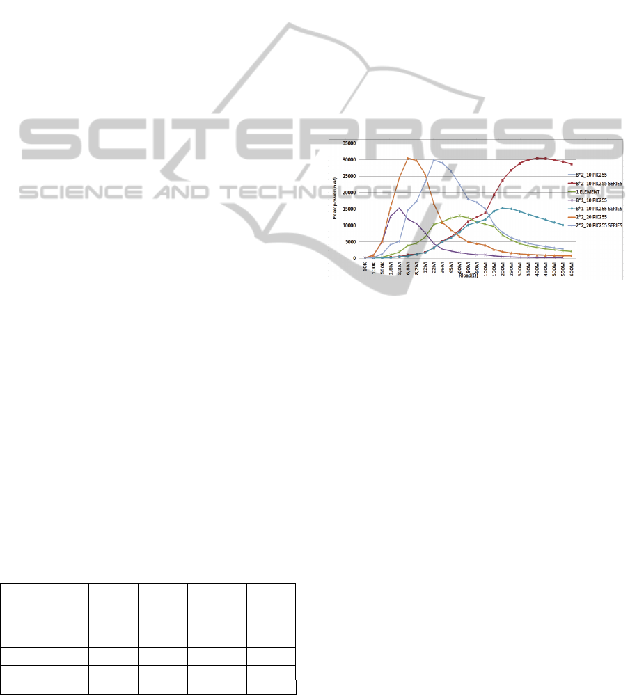
As expected AC measurements showed that the
generator performs best when the load resistance
matches the internal resistance of the main coil.
Unexpectedly, the average power decreased when
the subjects switched from walking fast to a running
state. The results of Figure 2 show that the optimal
speed is 8 km/h. At this point, the average power
graph shows that the values recorded are up to 4.5
mW average power, although the highest peak to
peak voltage was produced for a 10Ω load
resistance.
Figure 2: Peak- to- peak voltages and maximum output
power values at different walking speeds for different load
resistance for the electromagnetic generator.
BIODEVICES2013-InternationalConferenceonBiomedicalElectronicsandDevices
274
3.2 Piezoelectric Generator Design
Research in the field of piezoelectric energy
harvesting has been reviewed in papers like
(Sodano, 2005) and (Lefeuvre, 2006). Many authors
focus on the development of piezoelectric materials,
most of which are based on lead zirconate titanate,
also known as PZT (Anton, 2007). Based on a
comparison of generated power levels, Kymissis has
determined that different types of piezoelectric
material have different responses strongly connected
to the individual’s gait patterns (Kymissis, 1998).
The first aim of this research was to determine
the most suitable form of piezoelectric material for
producing a shoe in-sole generator, where the
highest forces available are due to the pressure of the
person’s weight acting under the sole of the foot.
Two different types of piezoelectric materials
have been taken into consideration: a PVDF film
having an area of 6x12 mm² from Measurements
Specialities (Measurement Specialities, US), and a
set of piezoceramic disks with diameters of 10 and
20 mm, and thicknesses of 1 and 2 mm from PI
(PhysikInstrumente GmbH & Co., Germany).
Table 3 compares the electrical performance of
the selected materials in terms of open-circuit
voltage as calculated, V
OCcal
, for an applied pressure
level of 400 kN/m
2
, (typical under the heel during
walking) (Perttunen, 2002). Measured results, V
OCm
,
are also presented for an estimated pressure of 94
kN/m
2
, and it is seen that there is generally good
agreement in the trends of calculated and measured
values.
Due to the low capacitance of the piezoelectric
elements, the capacitance of the probe (16pF/10MΩ)
affects the open-circuit measurement, and therefore
measured results are derived from an equivalent
circuit model of the piezoelectric elements, using
values of equivalent series capacitance, C
pz
, and
resistance, R
pz
, as listed in Table 3. Clearly
impedance values are much higher than the
electromagnetic coil resistance described in section
3.1.
Table 3: Comparison of test piezoelectric material
properties.
Materials C
pz
(pF)
R
pz
()
V
OCcal
(V) V
OCm
(V)
Polymer film 708
>1 M
34.0 na
PIC155 2x10 mm² 504
6.3 k
21.6 4.9
PIC255 2x10 mm² 608
5.2 k
20.0 4.7
PIC255 1x10 mm² 1210
2.8 k
10.0 2.59
PIC255 2x20 mm² 2430
1.3 k
20.0 2.87
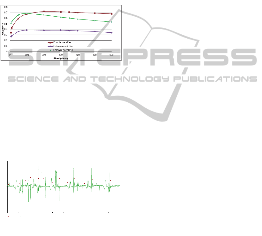
In order to compare power levels achievable
within the footprint area of a shoe heel, equivalent
circuit models of each piezoelectric element were
combined in series and parallel and results of peak
AC power were produced for a range of load
resistances. Results are presented in Figure 3.
The maximum peak instantaneous power
predicted is 30 W, which compares with 4.5 mW
average power for the electromagnetic generator of
section 3.1. Clearly, the piezoelectric generator is
not competitive in this environment and work is on-
going to review the choice of piezoelectric materials,
and methods for compensating the high impedance
of piezoelectric source capacitance. Another issue
that needs to be addressed in terms of designing a
piezoelectric generator is compensating the high
impedance capacity as this will lead to increased
output power values.
Figure 3: Maximum output power of piezocermaic disks
for different load resistance and associations.
4 ELECTROMAGNETIC AC/DC
CIRCUIT PERFORMANCE
After establishing that the electromagnetic generator
is better suited for the in-shoe design the most
optimal parameters and design for the generator
were selected. The next step was designing the
AC/DC conversion circuit, in order to provide a DC
power source as required by most portable devices.
Literature has proposed a number of different
rectification circuits (Wang, 2009) and (Rao, 2011).
Although many of the systems proposed have
shown good results, a number of them require
additional powering for active switches. As it is
desired that the proposed generator to be a self-
sustained system and that the generator voltage pulse
needs only to be rectified but not necessarily
regulated, the AC/DC conversion circuitry needed is
considered to be a more simplistic application of
basic conversion principles. Full investigations were
conducted for full-wave rectifier and half-wave
rectifiers and voltage doubler circuits. A set of
ComparisonofEnergyHarvestingTechniquesforWearableActivityMonitoringDevices
275
simulations were performed with the aid of pSpice
simulation software (Cadence Design Systems, UK)
for each type of rectifier with several load
resistances and capacitors values, and the results are
shown in Figure 4. The source used in each
simulation is represented by the generator open-
circuit waveform and a 6Ω resistor representing coil
resistance. In order to maximise the output power,
the PMEG 2010EH diodes were used as they present
lower forward voltage (Caroll, 2005).
Figure 4: Simulations results of maximum output power
for rectification circuits depending on load resistances for
3.5mF capacitor.
Due to the overall reduced voltage drop across
the diodes in the full- wave rectifier circuit, the
doubler circuit performed the best. The maximum
output power was achieved for 250 Ω, with a peak
instantaneous power value of 3 mW. Due to the fact
that the rectification was performed for a pulsed type
of power a capacitance value of 3.5mF was used, as
it provided increased values for the output voltage.
Figure 5 presents the input and the rectified
waveforms for the optimum load resistance.
Figure 5: Typical waveform generated by the prototype
during walking and the rectified waveform with a doubler
circuit for the optimum load resistance (250Ω).
5 CONCLUSIONS
Two different energy harvesting techniques have
been compared in order to prove their suitability to
power an activity monitoring device. The
electromagnetic generator has proved to be superior
to the piezoelectric system. With the given space of
50x15x15 mm
3
the generator produced power levels
of 4.5 mW AC and 0.8 mW for pulsed DC, almost
sufficient to meet the requirements of the nRF chip.
Work is on-going to investigate the effect of the
additional half coils over the output power.
However, the optimum speed being around 7-8 km/h
might make this type of energy harvesting system
more suitable for more active people. For the
piezoelectric system, the selection of materials
available for this work has not given the desired
outcome, with the piezoceramic disks giving low
output powers and being subjective to damage due
to repeated stress caused by the constant pressure
applied during walking. Although piezoelectric
components are capable of providing high output
voltage, the output power is limited by the loading
of the capacitive impedance.
REFERENCES
L. Mateu, F. Moll, and U. Polit, “Review of Energy
Harvesting Techniques and Applications for
Microelectronics,” Energy.
J. Paulo and P. D. Gaspar, “Review and Future Trend of
Energy Harvesting Methods for Portable Medical
Devices,” Engineering, vol. II, 2010.
H. A. Sodano, D. J. Inman, and G. Park, “Comparison of
Piezoelectric Energy Harvesting Devices for
Recharging Batteries,” Power, vol. 16, no. 10, pp.
799-807, 2005.
Arnold, D.P.; ‘Review of microscale magnetic power
generation’, IEEE Transactions on Magnetics, Vol.
43, No. 11, November 2007, pp. 3940 – 3951
Carroll. D, Duffy. M, Modelling, design, and testing of an
electromagnetic power generator optimized for
integration into shoes, Journal Article 2011, 8
September 9, 2011, Proceedings of the Institution of
Mechanical Engineers, Part I: Journal of Systems and
Control Engineering, Volume 226 issue 2, pages 256-
270
E. Lefeuvre, Badel, C. Richard, L. Petit, and D. Guyomar,
“A comparison between several vibration-powered
piezoelectric generators for standalone systems,”
Sensors and Actuators A: Physical, vol. 126, no. 2, pp.
405-416, Feb. 2006.
S. R. Anton and H. Sodano, “A review of power
harvesting using piezoelectric materials (2003–2006),”
Smart Materials and Structures, vol. 16, no. 3, pp.
R1–R21, Jun. 2007.
J. Kymissis, C. Kendall, J. Paradiso, and N. Gershenfeld,
“Parasitic power harvesting in shoes,” Digest of
Papers. Second International Symposium on Wearable
Computers (Cat. No.98EX215), pp. 132–139.
J. Perttunen, "Foot loading in normal and pathological
T
ime
5.0s 5.5s 6.0s 6.5s 7.0s 7.5s 8.0s 8.5s 9.0s 9.5s 10.0s
V(0,R2:1) V(R1:1,V1:-)
-
2.0V
-
1.0V
0V
1.0V
2.0V
BIODEVICES2013-InternationalConferenceonBiomedicalElectronicsandDevices
276

walking", PhD thesis, University of Jyvaskyla, 2002.
Y. Rao, David P. Arnold, “An Input-Powered Active
AC/DC Converter with Zero Standby Power for
Energy Harvesting Applications”, Energy Conversion
Congress and Exposition (ECCE), 2010 IEEE, 12-16
Sept., pp 4441 – 4446
G. Wang, C. Luo, H. Hofmann, L. Rome, ”Power
Electronic Circuitry for Energy Harvesting Backpack”,
Energy Conversion Congress and Exposition, ECCE
2009, 20-24 Sept. 2009, pp 3544 – 3549
D. Carroll, M. Duffy, “Demonstration of Wearable Power
Generator”, 11th European Conference on Power
Electronics and Applications, EPE’05 Dresden,
Germany, paper no. 884, CD ROM, September 2005.
ComparisonofEnergyHarvestingTechniquesforWearableActivityMonitoringDevices
277
