
Automated Planning for Pick-and-Place Robot
Yazmin S. Villegas-Hernandez and Federico Guedea-Elizalde
Design and Technology Innovation Center, Tecnologico de Monterrey, Monterrey, Mexico
Keywords:
Domain Language, Planner, Pick-and-Place Task, Automatic Assembly.
Abstract:
In this research was developed a language to describe a robot-based assembly. This language has an important
role in the generation of robot programs. To accomplish with the objective of automatic generation of robot
programs, it was developed a system, which consists on the next subsystems: a High-level-language Planner,
a Generic-level-language Parser and a Wrapper-generic-level language.
1 INTRODUCTION
The frequent changes in specifications, positions, di-
mensions, and assembly type of the products to as-
semble are the problem of many manufacture indus-
tries that use robots to do the work. To resolve this
problem, it is presented in this research an approach
to generate robot programs using planners. In order to
use this tool, it was developed a new domain language
to describe the assembly domain.
2 RELATED WORK
Automatic planning for production lines is a ma-
ture field with basic research moving to implemen-
tation cases. Car maker industries have many ben-
efits from the implementation of these planning tech-
niques. Even though, there are previous works related
with automatic planning systems as the work of Cho
et al., that describes the development of an automated
welding operation planning system for block assem-
bly in shipbuilding (K. Cho and Oh, 1999). Cho’s
system was divided in four modules that perform the
determination of welding postures, welding methods,
welding equipment and welding materials.
Another related work regarding of planning sys-
tems is the work of Zaho et al., where they present
an intelligent computer-aided assembly process plan-
ning system (ICAAPP) (Zhao and Masood, 1999) de-
veloped for generating an optimal assembly sequence
for mechanical parts. In the generation of assembly
sequences for any product, the critical problems to be
addressed include determining the base part, selection
of subassemblies, defining all necessary constraints,
and finally quantifying and solving these constraints.
In the innovative artificial intelligence approach
of Rabemanantsoa et al. (Rabemanantsoa and Pierre,
1996) for generating assembly sequences on a con-
sortium of database emulating expert systems, a CAD
(Computer-aided design) analyser is used for shape
and feature recognition, data structure and modelling,
knowledge-based representation, and inference pro-
cessing throughout a set of heuristics and rules.
In the work of Xue an automatic grasp planning
system for service robots is presented(Z. Xue and
Dillmann, 1996). In this system the semantic infor-
mation is represented as shape primitives, which are
treated by the grasp planning as obstacles or must-
touch regions of the object to influence the resulting
grasps.
In the work of Xu et al. it was developed an as-
sembly planning and simulation system called Au-
toAssem(L. Xu and Yu, 2012). This system is to au-
tomate assembly planning for complex products such
as aircraft components. They focused in the assem-
bly sequence planning to generate plans from a CAD
model with manual interventions.
In general, all of these systems consist of a plan-
ning process, use assembly graphs to generate se-
quences of assembly, or use another method; but none
of these systems generate the code to program the
robots online to perform welding and pick-and-place
operations like the approach suggested in this paper.
3 AUTOMATIC PLANNER
SYSTEM
The aim of this research is to develop a system that
547
S. Villegas-Hernandez Y. and Guedea-Elizalde F..
Automated Planning for Pick-and-Place Robot.
DOI: 10.5220/0004263205470550
In Proceedings of the 5th International Conference on Agents and Artificial Intelligence (ICAART-2013), pages 547-550
ISBN: 978-989-8565-39-6
Copyright
c
2013 SCITEPRESS (Science and Technology Publications, Lda.)

Figure 1: Automatic Planner System.
is capable of generating robot programs to assembly.
It was developed a system, which is shown in Figure
1 for this purpose, which is divided in the next sub-
systems: High-level-language Planner, Generic-level-
language Parser and Wrapper-generic-level-language.
This system produces a robot program written in
generic commands to do the assembly task.
3.1 High-level Planner
It was developed a language to describe the assembly
domain, in order to work with the Graphplan planner.
The language consists of propositions (to describe the
initial state) and operators (which are actions).
The planning process is defined as a tuple < P, A,
S
o
, G >, where P is a set of propositions in a language
Σ, A is a set of actions, S
o
⊂ P is the initial state, and
G ⊂ P is the goal state.
For example, an action A, meaning to pick and
place an object should be written as: (PickAndPlace
robot container1 fastener1), where container1 is the
picking location and fastener1 is the placing posi-
tion.
An example of the language to describe the ini-
tial state, S
o
, is (have container1 tube1), which rep-
resents that the container1 has the tube1.
Following the same reasoning, it is possible to
describe an assembly goal G, as (assemblyCorner90
tube1 tube2) which represent a Corner joint with an
angle of 90
◦
using the tubes: tube1 and tube2.
Let Σ =< Pn, L,C > be a first-order language
composed of a set of predicate names Pn =
{pn
1
, pn
2
, pn
3
, ..., pn
w
}, a set of literal constants
L = {l
1
, l
2
, l
3
, ..., l
n
}, and a set of classes C =
{c
1
, c
2
, c
3
, ..., c
m
}. The function f
c
:
f
c
: L → C
associates each literal constant to a class (or object
type). Then the set of literals (or propositions) P =
{p
1
, p
2
, p
3
, ..., p
w
}, where p
i
= (pn
x
, l
i1
....l
im
) is a list
involving constants and a predicate name. Also
ˆ
P =
( ˆp
1
, ˆp
2
, ˆp
3
, ..., ˆp
q
) is defined as a set of propositions,
where ˆp
i
= (pn
y
, l
i1
....l
ik
) is a list involving constants
and a predicate name too. Then we define the function
f
p
by:
f
p
: P →
ˆ
P
∀p
i
= (pn
x
, l
i1
, ..., l
ik
), f
p
(p
i
) = ˆp
j
:
ˆp
j
= (pn
x
, f
c
(l
i1
)... f
c
(l
ik
)).
This function is overload as:
F
p
: {P} → {
ˆ
P} : ∀J ⊂ P, F
p
(J) = f
p
( j
i
), ∀ j
i
∈ J.
An example of a literal is (have container1 tube1) ,
where have is a predicate name while container1 and
tube1 are literal constants of the class container and
tube.
Given an action A = {Pre, Post} as a set of
two kind of propositions: preconditions and post-
conditions of the initial state, S
o
, where preconditions
are the requirements to be accomplished before ac-
tion, and the post-conditions are the description of the
state after action. The function F
A
is defined as:
F
A
: {P} → {
ˆ
P}
∀a = {Pre, Post}, F
A
(a) = {F
p
(Pre), F
p
(Post)}.
Using these definitions, the planning problem can
be written in the proposed language with the form
{F
p
(P), F
A
(A), F
p
, S
o
, F
p
(G)}. The high-level plan is
obtained by applying the actions A to the initial state
F
p
(S
o
) to reach the goal F
p
(G). This high-level-
language plan will be parsed to obtain the robot pro-
gram.
3.2 Generic-level Parser
The generated high-level plan explained in the previ-
ous section, is the input to generic-level Parser. The
purpose of this subsystem is to act as intermediary be-
tween the Planner subsystem and the Robot system.
In order to accomplish this purpose, it was decided
to parse each high-level operation to produce generic-
level commands for the pick-and-place robot. This
parsing consists in recognizing a string (high-level-
operation) by dividing it into a set of symbols (or to-
kens) and analyzing each one of them against the de-
veloped grammar in this work.
Algorithm 1: ParseGenerator(E).
Require: A set of expressions E.
Ensure: Change every expression from high to generic level.
1: for e ∈ E, x ∈ instances o f e do
2: parsing: e(x)
3: Add e(x) to the robot program
4: end for
5:Compile robot program
Algorithm 1 provides a way to parse a set of high-
level-language expressions to generic-level-language
expressions. Step one retrieves every high-level-
language expression. Next, step two parses every ex-
pression from high to generic level. Then, step three
adds every parsed expression to the robot program.
ICAART2013-InternationalConferenceonAgentsandArtificialIntelligence
548
Finally, step four compiles the robot program with the
parsed expressions.
The grammar used for parsing consists in the fol-
lowing components (N,
∑
, P, S): nonterminal symbols
(N), terminal symbols (
∑
), production rules (P), and
a start symbol (S).
The nonterminal symbols that will be evaluated by
the semantic analyzer are: AddOp, PickPlace, Offsetx,
Offsety, Open, Close and Welding.
The terminal symbols are elementary symbols
of the language, and these symbols are a set of
terms that represent the high-level-language opera-
tions: EOF, NUMBER, BROPEN, BRCLOSE, OPS,
PARAM, COMMA, PICKANDPLACE, OFFSETX,
OFFSETY, OPEN, CLOSE, WELDING and WHITES-
PACE.
The production rules to do the parsing of some
expressions are shown in Table 1.
Table 1: List of grammar rules for this formal grammar.
AddOp -> (PickPlace)* (Offsetx)* (Offsety)*
(Open)* (Close)* (Welding)*
PickPlace -> PICKANDPLACE BROPEN
PARAM COMMA PARAM COMMA
PARAM COMMA PARAM BRCLOSE
Offsetx -> OFFSETX BROPEN PARAM
COMMA NUMBER BRCLOSE
Open -> OPEN BROPEN PARAM COMMA
PARAM BRCLOSE
The output of this parser is a program written in C-
Sharp-style for the CRS-F3 arm manipulator to pick-
and-place objects using the Generic-level-language-
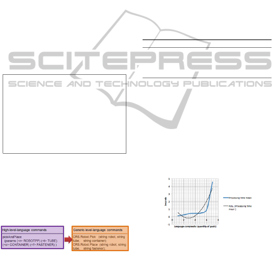
commands of the developed class library. Figure 2 de-
picts the sentences (high-level-language commands)
that are parsed to generic-level language commands.
Each of these sentences is parsed by the ParseProgram
class in the same order as all them are written in the
plan generated by the planner.
Figure 2: High-level-language commands parsed to
Generic-level-language commands.
3.3 Wrapper Program
In order to communicate the Parser subsystem with
the Robot system, it is used a Wrapper Program, in
order to execute the robot program.
The Wrapper-generic-level-language-functions
program consists in a set of wrapper methods written
in C ++ that uses the original functions of the CRS-F3
arm manipulator library, to make a set of generic
functions that have a standard form. These wrapper
methods are equivalent to the generic-level-language
methods in the Dynamic-Library-Link developed
in this research. Therefore, using this library it
will be able to do generic-robot programs, which
can be generated and executed using the developed
Graphic-User-Interface.
Algorithm 2 provides a way to execute each re-
quested action. Step one retrieves all actions re-
quested by the planner and step two executes them
all.
Algorithm 2: Wrapper(A).
Require: A set of action literals A.
Ensure: Do all requested actions
1: for a ∈ A, x ∈ instances of a do
2: execute a(x)
3: end for
4 EXPERIMENTAL RESULTS
The processing time of the High-level-language Plan-
ner subsystem and the Generic-level-language Parser
subsystem was tested in order to know the behavior
of this factor. In this test, it was used the same initial
state and the number of goals were changed in order
to obtain the mathematical model of the processing
time. In Figure 3 it can be seen the processing time
is polynomial, i.e. when the number of goals increase
the processing time increase in a polynomial way.
Figure 3: Polynomial Processing Time.
4.1 Language Experimental Results
It was tested the developed language in both plan-
ners: Graphplan and PDDL Graphplan(Planning Do-
main Definition Language). The description of the
initial state of the environment was written in this de-
veloped language for both planners. So, it was de-
scribed the welding table, which includes the orien-
tation, size, and order sequence of the fasteners. In
AutomatedPlanningforPick-and-PlaceRobot
549
this research work, the released language describes
three joint types: corner, T, and butt. There is one dif-
ference between the language versions used in both
planners, which consists that the one used in PDDL
planner have the advantage of use numerical values
to variables, while the other planner it is not possi-
ble. Another difference between the planners is the
processing time, where the Graphplan planner is the
faster. Finally, the PDDL planner has as limit 3 goals,
because the planner run out of memory, while the
Graphplan planner has as limit 10 goals.
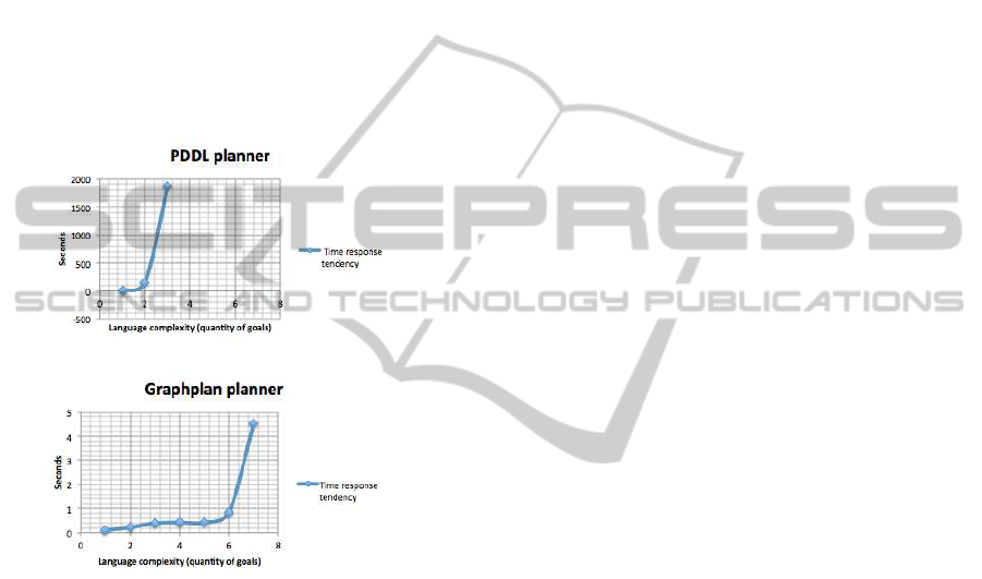
In Figure 4 is depicted the response time of both
planners. The response time of the Graphplan plan-
ner is lower than the PDDL planner. However, the
tendency of both planners is polynomial.
(a) PDDL planner time tendency
(b) Graphplan planner time tendency
Figure 4: Planner response times.
5 CONCLUSIONS
It was proposed the use of an assembly domain lan-
guage in combination with a parser in order to gener-
ate a robot program for pick-and-place tasks.
It was developed two versions of the developed
language (one for each planner used). The response
time of each language has a polynomial tendency.
The language version for graphplan planner has better
time results. So, it was decided to use the Graphplan
algorithm in the planner system.
It was concludedthat the system could accomplish
robot programs in seconds (if it has 10 or less goals).
Furthermore, it is possible to accomplish three joints
types: Corner, T, and But as goals.
ACKNOWLEDGEMENTS
This research was conducted in the Robotics Lab-
oratory at ITESM(Campus Monterrey). Villegas-
Hernandez’s research was partially supported by
ITESM and a fellowship from CONACyT.
REFERENCES
K. Cho, J. S. and Oh, J. (1999). An automated welding
operation planning system for block assembly in ship-
building. Production Economics.
L. Xu, C. Wang, Z. B. and Yu, J. (2012). Autoassem: An au-
tomated assembly planning system for complex prod-
ucts. IEEE Transactions on Industrial Informatics.
Rabemanantsoa, M. and Pierre, S. (1996). An artifi-
cial intelligence approach for generating assembly se-
quences in cad/cam. Artificial Intelligence in Engi-
neering.
Z. Xue, A. Kasper, M. Z. and Dillmann, R. (1996). An
automatic grasp planning system for service robots.
Artificial Intelligence in Engineering.
Zhao, J. and Masood, S. (1999). An intelligent computer-
aided assembly process planning system. The Interna-
tional Journal of Advanced Manufacturing Technol-
ogy.
ICAART2013-InternationalConferenceonAgentsandArtificialIntelligence
550
