Inertial Navigation System for Emergency Responders
A Foot Mounted Dead Reckoning System
Thies Keulen
Centre of Excellence for Intelligent Sensor Innovation, Hanze Institute of Technology,
Industrieweg 34A, Assen, The Netherlands
Keywords: Emergency Responders, Inertial Navigation, Dead Reckoning, ZUPT.
Abstract: It comes as no surprise that the jobs of first responders like police and firemen can be, and often are very
perilous. Police teams entering a building to arrest crime suspects, or fire-fighters entering an ablaze
building, bring with them serious hazards. For these kinds of situations, some sort of navigation module to
keep track of a person’s location at all times would be a solution. However, the fact that these situations
occur mostly inside buildings, complicates the picture. This paper presents research done on a foot mounted
inertial navigation system using zero velocity updates. These updates are done based on steps detected by a
pressure sensor. Current results show that this is a promising technique but there are still problems with
magnetic deviation due to metal in the building. Future work consist of adding other sensors such as a
barometric pressure sensor for floor height and ultrasonic range finding to perform simultaneous
localization and mapping (SLAM).
1 INTRODUCTION
Not knowing exactly where someone is can be
problematic for both the first responders actually
going in, as well as for commanders who supervise
their operations and try to coordinate them as well as
possible. In case of building collapse, for instance,
the position of the fire fighters in the debris is
usually not precisely known, making rescue attempts
troublesome. For a commander, knowing where his
men are could be crucial to the operation’s success.
For these situations, some sort of navigation module
to keep track of a person’s location at all times
would be a solution. However, the fact that these
situations occur mostly inside buildings, complicates
the picture. The physical structure and behaviour of
materials interferes with traditional methods of
navigation such as GPS systems and compasses.
Several methods for indoor navigation are not
suitable for these kinds of applications. For instance
segment scanning where a building is divided into
distinct segments or triangulation where signal
strength is used require external hardware. Setting
up these external devices is often not an option for
first responders. Other options such as using UWB
(Stromback et al., 2010
); (Bellusci, 2011), existing
WIFI (Evennou and Marx, 2006) connections or
building blueprints are not always available,
especially in older buildings. Therefore this project
aims at a standalone navigation device to be worn by
the police or the fire fighters.
2 HARDWARE
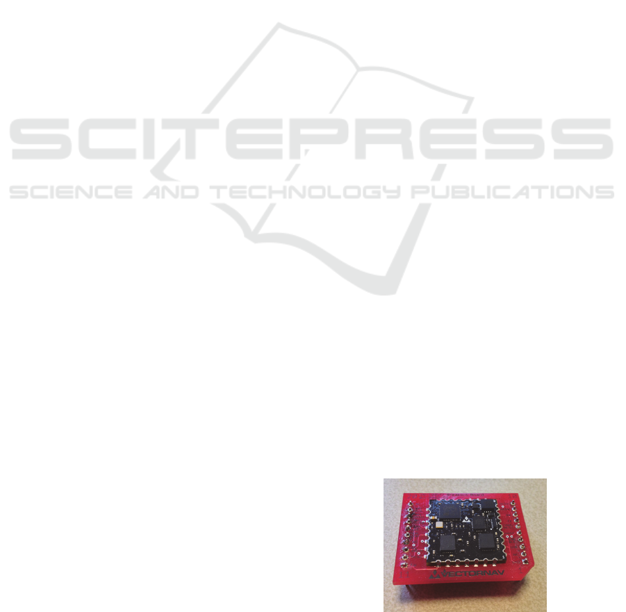
In this project we use a VN-100 sensor (Vectornav,
2012) (Figure 1) for measuring the acceleration,
angular rate and magnetic field strength in the three
inertial axes.
Figure 1: The VN-100 IMU, produced by VectorNav and
which is central to this project.
The most important features of the VN-100 are
its MEMS based sensors. Each VN-100 chip
contains a 3-axis gyroscope, 3-axis accelerometers
173
Keulen T..
Inertial Navigation System for Emergency Responders - A Foot Mounted Dead Reckoning System.
DOI: 10.5220/0004272401730176
In Proceedings of the 2nd International Conference on Sensor Networks (SENSORNETS-2013), pages 173-176
ISBN: 978-989-8565-45-7
Copyright
c
2013 SCITEPRESS (Science and Technology Publications, Lda.)
and 3-axis magnetometers. These sensors are
constantly sampled, with raw values being written
into registers that can be read out by users. The VN-
100 however, can already perform a lot of the
calculations necessary to convert these
measurements into an attitude solution. To estimate
attitude, the sensor employs quaternion mathematics.
This is done automatically by the chip, and takes
into account the offsets created by, for example,
gravity and the earth’s magnetic field.
Because data can be noisy and problems like
sensor drift could account for some errors in
measurement, the VN-100 makes use of an extended
Kalman filter to both reduce noise and give the best
estimate as to the current attitude solution. Because
this filter is run on the chip, no detailed information
about the mathematical model is necessary to work
with it. What is important to know is that the
parameters of this filter can be adjusted by the user,
to tweak the sensor for optimal performance in a
desired situation.
To interface with the sensor, read out its registers
and perform the necessary calculations to come to
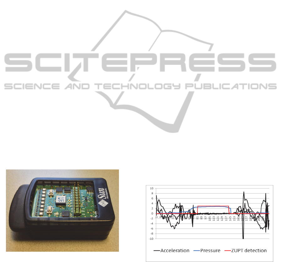
the position solution, the SunSPOT was used as the
sensor platform (Oracle Labs, 2012) (Figure 2). The
SunSPOT is a prototyping platform developed by
Sun Microsystems. It is programmable in the JAVA
language, and offers a series of inputs/outputs to
interface with sensors or other peripheral hardware.
Using a build-in radio, the SunSPOT is capable of
wireless communication up to 20m in theory,
although this range can be increased by connecting
for example an XBee radio.
Figure 2: The SunSPOT, developed by Sun Microsystems,
and which is used as prototyping platform for this project.
3 INTEGRATION
With the accelerations and attitude in the earth
inertial reference frame coming from the VN-100
sensor we can calculate the distance travelled for all
axes using double integration. However when
calculating velocity and distance from these
measurements by integration an integration error is
accumulated. The sensor's velocity and thus distance
keeps increasing even when the IMU is stationary.
By using low cost IMU's for navigation purposes the
errors accumulate in such a rapid rate that it is no
longer suitable for the application.
3.1 ZUPT
Zero Velocity Updates (ZUPT), a method used to
improve the long-term accuracy of the IMU is used
in this project. Since the application we are
developing is supposed to track the position of a
person in a building, the sensor node needs to be
placed somewhere on the user’s body. In order to
improve long term accuracy of the INS the sensor
node is placed on the foot of the user. After each
step there is a moment in which the foot is
stationary, thus the velocity of the foot is zero.
Because we know the velocity should be zero at
mid-stance we can set the calculated velocity back to
zero, meaning that the errors previously
accumulated will not have an effect on future
measurements, thus improving long term accuracy
(Park and Suh, 2010); (Skog et al., 2010). To detect
a footstep this project uses a pressure sensor located
beneath the middle of the foot. Figure 3 shows the
detection of the ZUPT periods in between the
acceleration. The pressure sensor allows us to detect
a footstep regardless of how fast you walk. Other
methods such as magnitude or variance detection
tend to lose accuracy at higher speeds.
Figure 3: ZUPT detection using a pressure sensor.
There is however another source of error in
determining distance. Despite having very dense
data sets with roughly 100 measurements per
second, the integration is never perfect. Sudden
abrupt movements have been found to be
SENSORNETS2013-2ndInternationalConferenceonSensorNetworks
174
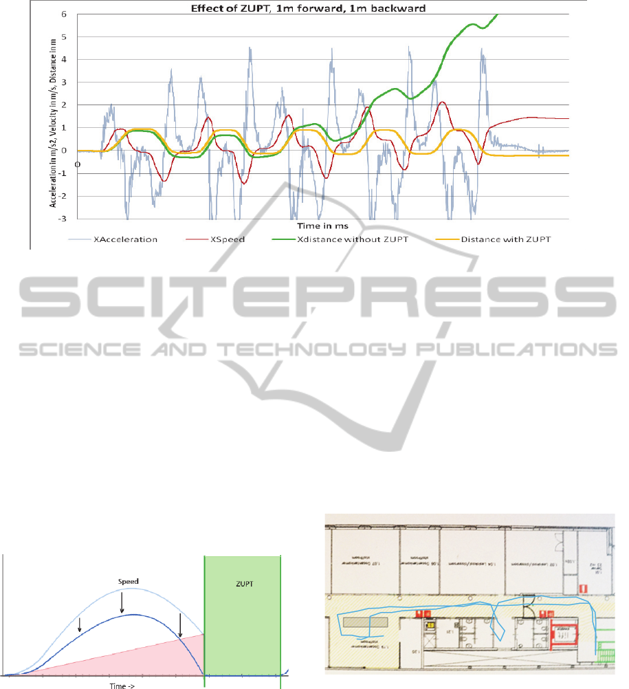
Figure 4: Effects of ZUPT on a data set.
particularly harmful to the quality of the sensor data.
In theory, when the ZUPT method kicks in to reset
the velocity to zero, the result of the first integration
giving velocity should also yield zero. This is
however, almost never the case. In most cases, the
velocity just before ZUPT differs minimally from
zero (in the order of 0.01-0.1 m/s), but sometimes
this deviation after a step is larger.
Observation of larger datasets taken over a period of
walking, seem to suggest the error is linear in nature,
slowly increasing the error in velocity over time,
which is best seen in datasets with ZUPT turned off.
This leads to the conclusion that to adjust for the
error, the red shaded triangle in Figure 5 needs to be
subtracted from the overall integral.
Figure 5: Correction of the integration. Subtraction of the
area in error results in moving the velocity graph down,
which is shown to produce an increase in displacement
calculation accuracy.
The effect of this ZUPT method is shown in
Figure 4. It is clearly visible that using this kind of
feedback method is essential to the accuracy of an
inertial navigation system based on these sensors.
This test represents a person continuously stepping 1
m forwards and backwards.
4 CURRENT STATE
Currently the following test result can be displayed,
see Figure 6. This picture displays someone walking
through our building and getting back to the starting
place.
There are however moments where the sensor
chip looses orientation due to metal in the building.
The VN-100 sensor already has a filter that can try
to correct this, but unfortunately this is not enough.
Figure 7 clearly shows what happens when the
orientation gets lost.
Figure 6: Test walk through the building.
We are looking into other feedback methods to
help the navigation system calculate the location.
One of these is a barometric pressure sensor to
detect floor levels. Results of this sensor can be seen
in Figure 8 showing a person walking down three
floors and back up again.
However the barometric pressure will change
rapidly in a burning building, therefore a
combination between sensors should be found.
InertialNavigationSystemforEmergencyResponders-AFootMountedDeadReckoningSystem
175
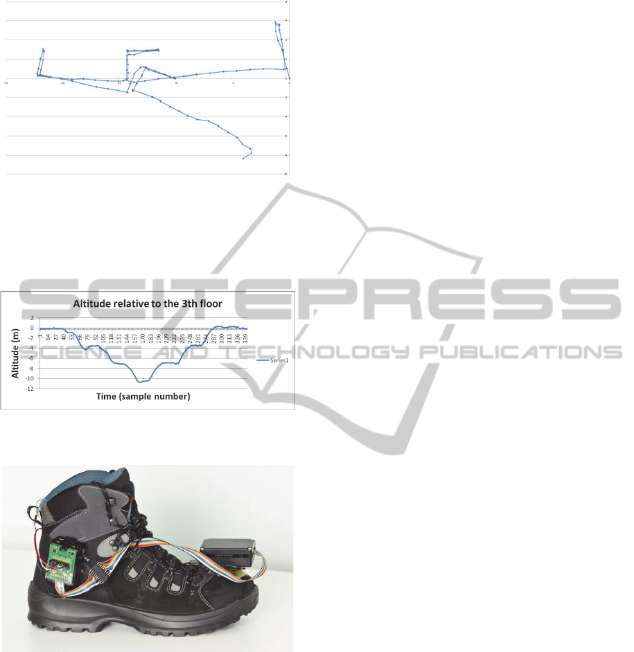
Figure 7: Orientation loss resulting in a wrong calculated
path.
Next to that we are working on integrating the
proof of concept seen in Figure 9 into the shoe,
making the solution more robust.
Figure 8: Barometric pressure sensor detecting floor
levels.
Figure 9: Current proof of concept.
5 CONCLUSIONS
Overall we conclude that an indoor navigation
system based on inertial dead reckoning is feasible
but will inevitably result in errors due to magnetic
interference and sensor inaccuracy. Therefore other
feedback / aiding systems are required to keep
navigation accurate for an extended period of time.
Zero velocity updates on footsteps detected by a
pressure sensor and floor detection using a
barometric pressure sensor are examples of that.
Further research is to be done on heading correction
using e.g. ultrasonic sonar mapping of walls.
REFERENCES
Stromback, P., Rantakokko, J. and Emilsson, E., (2010).
On the use of foot-mounted INS, UWB-ranging and
opportunistic cooperation in high-accuracy indoor
positioning.
Giovanni Bellusci. (2011). Ultra-Wideband Ranging for
Low-Complexity Indoor Positioning Applications.
Frédéric Evennou and Francois Marx, (2006). Advanced
Integration of WiFi and Inertial Navigation Systems
for Indoor Mobile Positioning systems.
Vectornav. (2012). Vectornav products. Available:
http://www.vectornav.com/products
Oracle Labs. SunSPOT. Available:
http://www.sunspotworld.com
Park, S. K. and Suh, Y. S., (2010). A Zero Velocity
Detection Algorithm Using Inertial Sensors for
Pedestrian Navigation Systems.
Skog, I., Nilsson, J. and Handel, P., 2010. Evaluation of
Zero-Velocity Detectors for Foot-Mounted Inertial
Navigation Systems. 09 2010.
SENSORNETS2013-2ndInternationalConferenceonSensorNetworks
176
