
RGB-D Tracking and Reconstruction for TV Broadcasts
Tommi Tykk
¨
al
¨
a
1
, Hannu Hartikainen
2
, Andrew I. Comport
3
and Joni-Kristian K
¨
am
¨
ar
¨
ainen
4
1
Machine Vision and Pattern Recognition Laboratory, Lappeenranta University of Technology (LUT Kouvola),
Lappeenranta, Finland
2
Department of Media Technology, Aalto University, Aalto, Finland
3
CNRS-I3S/University of Nice Sophia-Antipolis, Nice, France
4
Department of Signal Processing, Tampere University of Technology, Tampere, Finland
Keywords:
Dense Tracking, Dense 3D Reconstruction, Real-time Tracking, RGB-D, Kinect.
Abstract:
In this work, a real-time image-based camera tracking solution is developed for television broadcasting studio
environments. An affordable vision-based system is proposed which can compete with expensive matchmov-
ing systems. The system requires merely commodity hardware: a low cost RGB-D sensor and a standard
laptop. The main contribution is avoiding time-evolving drift by tracking relative to a pre-recorded keyframe
model. Camera tracking is defined as a registration problem between the current RGB-D measurement and
the nearest keyframe. The keyframe poses contain only a small error and therefore the proposed method is
virtually driftless. Camera tracking precision is compared to KinectFusion, which is a recent method for si-
multaneous camera tracking and 3D reconstruction. The proposed method is tested in a television broadcasting
studio, where it demonstrates driftless and precise camera tracking in real-time.
1 INTRODUCTION
Rendering virtual elements, props and characters to
live television broadcast combines augmented reality
(AR) and video production. A robust camera esti-
mation method is required for rendering the graphics
from camera viewing direction. In film industry the
process is known as matchmoving and it is tradition-
ally done in post-processing (Dobbert, 2005). Match-
moving typically requires manual effort because the
available tools are not fully automatic. In online
broadcasting, special hardware based solutions exist
for automatic camera tracking, but their value is de-
graded by limited operating volume, weaker reality
experience and expensive price.
The goal of this work is to develop an affordable,
portable and easy-to-use solution for television pro-
duction studios. Marker-based AR techniques, such
as ARToolKit (Kato and Billinghurst, 1999), are triv-
ial to use but visible markers are irritating in the studio
scene. Thus, we seek solution from more recent tech-
niques which are able to track the camera without any
markers. Visual simultaneous localisation and map-
ping (vSLAM) techniques are a true option, because
they track the camera using a 3D model which is con-
currently built based on visual measurements (Davi-
son et al., 2007). Recently, low-cost RGB-D sensors
have developed to a level where they can provide real-
time stream of dense RGB-D measurements which
are directly usable for camera tracking and scene re-
construction purposes.
In this work, we introduce an image registra-
tion based dense tracking and reconstruction method
particularly for TV studios. Tracking precision is
good, but over long sequences, time-evolving drift
will eventually displace virtual props. We avoid drift
by generating a RGB-D keyframe model, and track-
ing the camera relative to the nearest keyframe. The
results are demonstrated with real studio shots. We
thank Heikki Ortamo and Jori P
¨
olkki for their profes-
sional support in a TV production studio.
1.1 Related Work
Traditionally vSLAM methods detect and track a
sparse set of feature points which are matched in sev-
eral images. The first feature-based visual SLAM
methods used the extended Kalman filter (EKF) to up-
date pose and structure (Davison et al., 2007). How-
ever, bundle adjustment has replaced EKF, because
it is more accurate. PTAM (Klein and Murray,
2007) separated tracking and mapping into two par-
247
Tykkälä T., Hartikainen H., Comport A. and Kämäräinen J..
RGB-D Tracking and Reconstruction for TV Broadcasts.
DOI: 10.5220/0004279602470252
In Proceedings of the International Conference on Computer Vision Theory and Applications (VISAPP-2013), pages 247-252
ISBN: 978-989-8565-48-8
Copyright
c
2013 SCITEPRESS (Science and Technology Publications, Lda.)

allel modules, where the mapping part was essen-
tially bundle adjustment. To avoid feature extraction
and matching problems, the raw pixel measurements
can be used directly. DTAM was introduced as the
dense version of PTAM, which allows every pixel
to contribute to pose and structure estimation (New-
combe et al., 2011a). Finally, with KinectFusion sys-
tem which replaces monocular camera by a RGB-D
sensor (Newcombe et al., 2011b), pose tracking and
structure estimation have become mature enough to
be considered for live TV broadcasts.
In this work, we adopt the dense RGB-D ap-
proach (Tykkala et al., 2011; Audras et al., 2011;
Comport et al., 2007). Our method differs rather
strongly from the KinectFusion, because we estimate
camera pose using dense RGB-D measurements in-
stead of depth maps only. This is necessary because
studio settings often contain planar surfaces for which
the KinectFusion fails to track the camera. We do
not estimate 3D structure concurrently because it can
be solved prior to broadcasting. This simplification
lightens computation and enables running the system
with a low-end hardware. Robustness to outlier points
is increased by selecting the photometrically stable
pixels and by omitting unreliable regions (occlusion
and moving objects) with the M-estimator.
2 DENSE TRACKING METHOD
2.1 Cost Function
Our dense pose estimation is defined as a direct
color image registration task between the current im-
age I : R
2
⇒ R and a frame K
∗
= {P
∗
,c
∗
}, where
P
∗
= {P
1
,P
2
,...,P
n
} is a set of 3D points and c
∗
=
{c
1
,c
2
,...,c
n
} are the corresponding color intensi-
ties. Our goal is to find the correct pose increment
T(ω,υ) which minimizes the following residual:
e = I (w (P
∗
;T(ω,υ))) −c
∗
, (1)
where w(P ; T) is a projective warping function which
transforms and projects P into a new view using the
4 ×4 transformation matrix T and the intrinsic ma-
trix K (constant, omitted in the notation). The exact
formula is
w(P ; T, K) = w
P ;
R t
0 1
,K
= N(K(RP +t)),
(2)
where N(p) = (p
1
/p
3
, p
2
/p
3
) dehomogenizes a
point. T(ω,υ) is defined as the exponential mapping
which forms a Lie group T(ω,υ) ∈ SE(3) (Ma et al.,
2004):
T(ω,υ) = e
A(ω,υ)
, A(ω,υ) =
[ω]
×
υ
0 0
, (3)
where ω and υ are 3-vectors defining rotation and
translation. From the practical point of view it is con-
venient to re-define (3) as
T(ω,υ) =
b
Te
A(ω,υ)
, (4)
which generates smooth increments around the base
transform
b
T. This allows using iterative optimization
and particularly the inverse compositional trick for
estimating the transformation efficiently (Baker and
Matthews, 2004).
2.2 Minimization
We adopt the inverse compositional approach for ef-
ficient minimization of the cost function (Baker and
Matthews, 2004). The cost is reformulated as
c
∗
(ω,υ) = I
∗
w
P
∗
;e
−A(ω,υ)
e = c
∗
(ω,υ) −I
w
P
∗
;
b
T
,
where reference colors c
∗
are now a function of the
inverse motion increment. The benefit is gained when
computing the Jacobian
J
i j
= ∆I
∗
(w(P
i
;I))
∂w(P
i
;I)
∂x
j
, (5)
where ∆I (p) = [
∂I (p)
∂x
∂I (p)
∂y
]. By this trick J does not
depend on the current transformation anymore and it
is sufficient to computed it only once for each K
∗
.
Gauss-Newton iteration is well-suited for minimiza-
tion when the initial guess is near the minimum and
the cost function is smooth. The cost function is lo-
cally approximated by the first-order Taylor expan-
sion e(x) = e(0) +Jx, where e(0) is the current resid-
ual. Now the scalar error function becomes
1
2
e(x)
T
e(x) =
1
2
e(0)
T
e(0) + x
T
J
T
e(0) +
1
2
x
T
J
T
Jx
(6)
where the derivative is zero when
J
T
Jx = −J
T
e(0) . (7)
Because J
T
J is a 6 ×6 positive definite matrix,
the inversion can be done efficiently using Cholesky
method. The matrix multiplication associativity in
SE(3) enables collecting the previous increments into
the base transform by
c
T
k
···
c
T
1
e
A(ω,υ)
⇒
b
Te
A(ω,υ)
(4).
VISAPP2013-InternationalConferenceonComputerVisionTheoryandApplications
248
2.3 Keyframe based Reference K
∗
Minimisation of the cost function (1) with the Gauss-
Newton method in Sec 2.2 provides us real-time dense
RGB-D camera tracking (and scene reconstruction),
which frame by frame finds the optimal transforma-
tion T(ω,υ) between a previous frame K
∗
and a cur-
rent frame (image I ). This approach has one disad-
vantage: small per frame estimation error cumulates
into global drift which gradually displaces virtual el-
ements. Fortunately, the studio scene can be pre-
recorded into a set of keyframes prior to broadcasting
(see Fig. 1). The tracking is then defined relative to
the nearest keyframe K
∗
← select closest(K
∗
j
). For
small studios, a single dense tracking sweep is suffi-
cient, but methods exist also for building larger mod-
els (Henry et al., 2012).
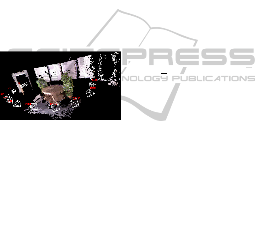
Figure 1: Stored scene keyframes and their pixels mapped
to a common 3D world model.
2.4 Robust Estimation
Now we know that our reference keyframes contain
merely static geometry with Lambertian reflection, it
is possible to increase robustness of the estimation
by emphasising stronger color and depth correlation
between the static reference points and the current
3D points matched in each iteration. We do this by
employing M-estimation in which uncertainty based
weights w
k
∈ [0, 1] ∈ R are given to the residual ele-
ments e
k
. Color correlation is enforced by the Tukey
weighting function
u
k
=
|e
k
|
c ∗median(e
a
)
, (8)
w
c
k
=
(
(1 −(
u
k
b
)
2
)
2
if |u
k
| <= b
0 if |u
k
| > b
, (9)
where e
a
= {ke
1
k,...,ke
n
k}, c = 1.4826 for robust
standard deviation, and b = 4.6851 is the Tukey spe-
cific constant.
The depth correlation weights are computed si-
multaneously by a depth lookup
e
z
= Z (w(P ; T(ω,υ))) −e
T
3
T(ω,υ)
P
1
, (10)
where Z : R
2
⇒ R is the depth map function of the
current RGB view and e
T
3
= (0,0,1,0) selects the
depth coordinate. When the standard deviation of
depth measurements is τ, the warped points whose
depth differs more than τ from the current depth map
value can be interpreted as foreground actors/outliers.
Thus we define a diagonal matrix
w
z
k
= max
(1 −e
2
z
(k)/τ
2
),0
2
, (11)
The weighted Gauss-Newton step is obtained by
re-writing (7)
J
T
WJx = −J
T
We, (12)
where W is a diagonal matrix with diag(W)
k
=
w
k
c
w
k
z
. The robust step is obtained by J ⇐
√
WJ
and e ⇐
√
We. The both weight components are
quadratic and therefore the square roots are not eval-
uated in practise.
2.5 Selecting Keyframe Points
The reference points P
∗
can be freely selected from
the keyframe. When considering the minimization
of the photometrical error, only the 3D points with
image gradients infer pose parameters. Therefore the
majority of the points can be neglected based on the
magnitude of the image gradient. Gradient vector
∇c is evaluated at the projection of P
∗
using bilin-
ear interpolation. Instead of sorting |∇c|, we generate
the histogram of the magnitudes. The value range is
bounded to [0,255]. We seek the bin B
t
for which
Σ
255
k=B
t
−1
h(k) < n <= Σ
255
k=B
t
h(k), where n is the num-
ber of points to be selected.
3 IMPLEMENTATION DETAILS
Our method was implemented in Ubuntu Linux en-
vironment using open software tools, Kinect RGB-
D sensor and a commodity PC laptop hardware on
which the method runs real-time. The main limita-
tions are the operating range (≈ 1m −5m) and that
it uses controlled IR lighting which may not work in
outdoors. Below, we discuss Kinect related imple-
mentation issues.
RGB-DTrackingandReconstructionforTVBroadcasts
249
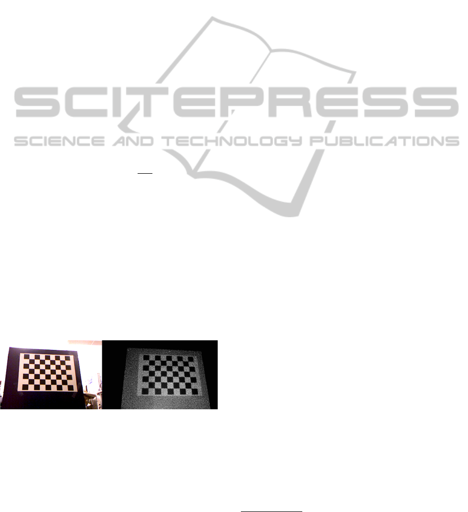
3.1 Kinect Calibration
Since Microsoft Kinect can be set into a special mode
where the raw IR images can be stored, it is possible
to use standard stereo calibration procedure for ob-
taining the calibration parameters for the IR and the
RGB view (Bouguet, 2010) (Fig. 2). IR view and the
depth view are trivially associated with image offset
(−4,−3).
A single camera calibration is used to initialize
IR and RGB camera parameters. Then calibration
is followed by a stereo procedure which re-estimates
all free parameters (K
IR
, K
RGB
, kc
RGB
,T
b
). The lens
distortion parameters of the IR camera are forced to
zero, because data has already been used to gener-
ate the raw disparity map. This means that the IR
lens distortion is compensated by tweaking other pa-
rameters. The RGB camera lens distortion parameters
kc
RGB
are estimated without any special concerns. In
practice, the distortion seems to be minor and the
first two radial coefficients are sufficient (kc
RGB
=
(0.2370,−0.4508,0,0,0), and the stereo baseline is
b = 25.005mm. T
b
stores the baseline transform as
4×4 matrix. The conversion from raw disparities into
depth values can be done by z =
8p f
B−d
, where p is the
baseline between the projector and the IR camera, B
is a device specific constant and f is IR camera fo-
cal length in pixel units. p and B are estimated by
solving the linear equation
−1 Z
A B
T
= D,
where A = 8p f , Z is n ×1 matrix of reference depth
values z
k
from the chessboard pattern (Caltech cali-
bration), and D is a n ×1 matrix whose elements are
d
k
z
k
. The parameters will be p ≈75mm and B ≈1090.
Note, that this reconstruction method is merely an ap-
proximation which procludes measurements at long
ranges. There are also dedicated calibration toolboxes
for RGB-D sensors, which model disparity distortion
accurately (Herrera et al., 2012).
Figure 2: RGB and IR images of the calibration pattern.
3.2 Dense Tracking with Kinect
The reference point clouds
{
P
∗
,c
∗
}
in (1) were gen-
erated from Kinect RGB image and disparity map in
the following way. Kinect Bayer images were con-
verted into RGB format, downsampled into 320x240
and undistorted from lens distortions. Downsampling
is almost lossless due to sparsity of RGB values in the
Bayer pattern. The raw disparity map was first con-
verted into a depth map, downsampled into 320x240
size using max filter and then transformed into a point
cloud P
∗
IR
. Maximum filtering is chosen because it
does not produce artificial geometry. P
∗
was then
generated from T
b
P
∗
IR
, where T
b
is the baseline trans-
formation between the IR and RGB cameras. Points
p ∈ P
∗
do not exactly project to the pixel centers of
the RGB image grid, and thus, bi-linear interpolation
is used for generating the corresponding intensities c
∗
.
The cost function is minimized using coarse-to-
fine approach using image pyramid with 80 × 60,
160×120 and 320×240 layers for each RGB-D input
frame.
4 EXAMPLES
4.1 Dense Tracking vs Kinfu
Kinfu is the open source implementation of Kinect-
Fusion (Rusu and Cousins, 2011). We compare our
dense tracking accuracy with Kinfu using the RGB-
D SLAM benchmark provided by Technical Univer-
sity of M
¨
unich (Sturm et al., 2011) (Figure 3). Dense
tracking is executed incrementally by using a recent
view as the reference. Thus, both methods aim at
tracking the camera pose without a prior model and
small drift will be present. The major difference be-
tween the systems is that Kinfu optimizes a voxel
based 3D structure online and uses the iterative clos-
est point (ICP) approach for pose estimation. Kinfu
has small drift when the voxel size is small and geom-
etry is versatile. Kinfu fails in bigger operating vol-
umes, because voxel discretization becomes coarse
and, for these sequences especially, the volume will
also contain planar floor which break downs ICP
1
.
In broadcasting studios, scenes are often larger than
(3m)
3
and geometrical variations can not be guaran-
teed. Our dense tracking demonstrates robust track-
ing even when planar surfaces are present, because
the cost function matches also scene texturing. Mem-
ory consumption is low even in larger operating vol-
umes, because RGB-D keyframes can be memory-
optimized based on the viewing zone.
Table 1 shows the comparison between our
method and Kinfu numerically. The dense track-
ing drifts 1.08cm/s with the slower freiburg2/
desk sequence and 2.60cm/s with the faster
freiburg1/desk sequence. Our dense tracking has
smaller error when the camera is moving faster. Kinfu
1
Video: http://youtu.be/tNz1p1sdTrE
VISAPP2013-InternationalConferenceonComputerVisionTheoryandApplications
250

Table 1: Drift is evaluated using standard sequences with
known ground truth trajectories. The proposed approach
has smaller drift when a camera is moving faster. The
keyframe model can be memory-efficiently built. Kinfu has
smaller drift when a camera is moving slower but bigger
scenes are not possible due to inscalability of the voxel grid.
Problems exist with planar surfaces. The computational re-
quirements are higher even though Kinfu is executed on a
powerful desktop hardware.
Dataset Our drift Kinfu(3) Kinfu(8) Camera speed
freiburg1/desk 2.60cm/s 8.40cm/s 3.97cm/s 41.3cm/s
52.2ms 135ms 135ms
freiburg2/desk 1.08cm/s 0.64cm/s 1.30cm/s 19.3cm/s
35.5ms 135ms 135ms
has lower drift when using (3m)
3
voxel grid, but fails
to operate in bigger volumes (8m)
3
that match with
broadcasting studios. Also the computational require-
ments of Kinfu are significantly higher compared to
our approach even though Kinfu is executed on a pow-
erful desktop hardware. Drift was measured by divid-
ing the input frames into subsegments of several sec-
onds (10 and 2 correspondingly) whose median error
was measured against the ground truth. 1 second aver-
age error was computed from the median subsegment.
The error values are computed from bigger windows
to average out random perturbations and neglect gross
tracking failures which occur with Kinfu in all cases
except on freiburg2/desk using (3m)
3
volume.
4.2 Driftless Keyframe Tracking
The relative poses between the keyframes could,
in theory, be obtained by bundle adjustment tech-
niques (Triggs et al., 2000) if feature point extrac-
tion and matching succeeded, and a good initial guess
would exist. With the studio sequences recorded,
texturing was so limited that popular tools, such as
Bundler (Snavely et al., 2006) failed without manual
annotated feature points. As an alternative solution,
we utilised the proposed dense RGB-D tracker to in-
crementally build a keyframe model. It is noteworthy,
that a single quick sweep of the scene produces accu-
rate keyframe model
2
. Figure 4 illustrates how dense
tracking is used to sweep a keyframe model of the stu-
dio scene rapidly. With pre-recorded keyframes, the
online broadcasts are guaranteed to operate with the
correct 3D geometry. K
∗
j
were selected by picking
RGB-D frames evenly from the recorded sequence.
A keyframe database is illustrated in Figure 1.
In Figure 5, we show how the drift increases in a
studio environment when using dense tracking. On
the right-hand side, the drift problem is solved by
2
Video: http://youtu.be/wALQB3eDbUg
Figure 3: On the left Kinfu result for freiburg desk2 se-
quence using 3x3x3, 5x5x5 and 8x8x8 meter voxel volume.
Kinfu gains lower drift due to structural optimization, but
planar surfaces cause tracking failures. 3x3x3 volume does
not contain floor and therefore Kinfu works well. Limited
operating volume is a problem for practical use in the stu-
dio. On the right, our dense tracking drift illustrated when
a fixed keyframes are not used. Problems with planar sur-
faces or limited operating volume do not exist. Green dots
reveal the selected points for given RGB-D measurement.
Figure 4: Camera trajectory solved from Kinect input by
minimizing the cost function (1). A small shark is rendered
into the studio scene.
tracking relative to keyframes
3
. Note that in long-
term use, even a small number of keyframes eventu-
ally outperforms the dense tracking due to drift. How-
ever, a small keyframe number produces drift jumps
between the keyframes which can be visually disturb-
ing. With sufficient number of keyframes, the error
remains small.
5 CONCLUSIONS
In this work, camera pose tracking was defined as a
photometrical registration problem between a refer-
3
Video: http://youtu.be/zfKdZSkG4LU
RGB-DTrackingandReconstructionforTVBroadcasts
251
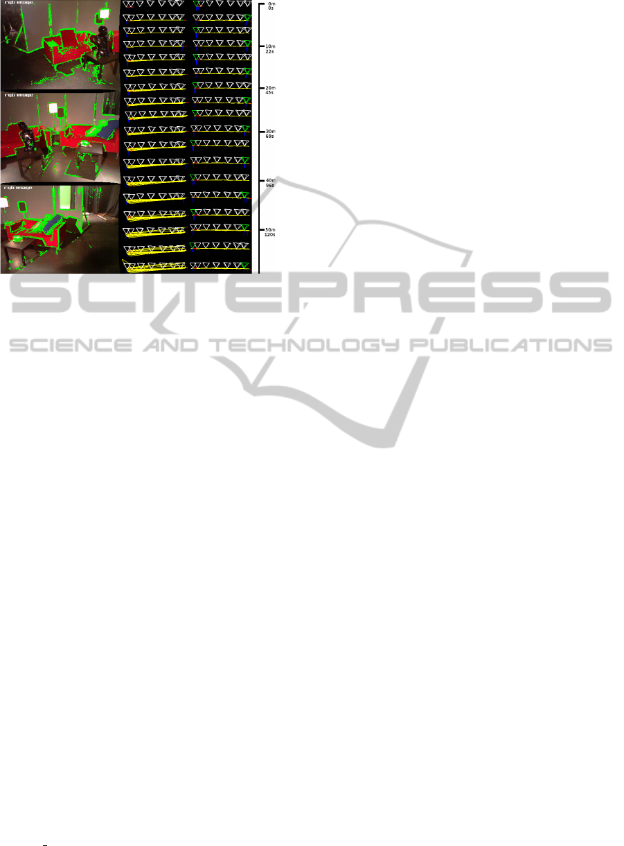
Figure 5: Camera moving front and back along a fixed
3.30m studio rail. On the left, three images taken from
the beginning, middle and the end of the rail. Green re-
gions illustrated selected points. On the right, comparison
between dense tracking and keyframe tracking. In dense
tracking drift increases in time, but keyframe tracking main-
tains small bounded error. A person is moving in the scene
during the last four cycles.
ence frame and the current frame. To remove the
global drift in incremental tracking, the closest pre-
recorded keyframe was chosen to be the motion refer-
ence. The system was designed to be an affordable so-
lution for TV broadcasting studios relying only on the
Kinect sensor and a commodity laptop. The proposed
approach performs robustly in a standard benchmark,
where KinectFusion has problems with planar sur-
faces and limited voxel grid resolution. Our future
work will address the practical issues how studio staff
and camera men can use our computer vision system
in live broadcasts. Moreover, combination of the best
properties of our approach and KinectFusion will be
investigated.
REFERENCES
Audras, C., Comport, A. I., Meilland, M., and Rives, P.
(2011). Real-time dense rgb-d localisation and map-
ping. In Australian Conference on Robotics and Au-
tomation. Monash University, Australia, 2011.
Baker, S. and Matthews, I. (2004). Lucas-kanade 20 years
on: A unifying framework. Int. J. Comput. Vision,
56(3):221–255.
Bouguet, J.-Y. (2010). Camera calibration toolbox
for matlab. http://www.vision.caltech.edu/bouguetj/
calib doc.
Comport, A., Malis, E., and Rives, P. (2007). Accu-
rate quadri-focal tracking for robust 3d visual odome-
try. In IEEE Int. Conf. on Robotics and Automation,
ICRA’07, Rome, Italy.
Davison, A., Reid, I., Molton, N., and Stasse, O. (2007).
MonoSLAM: Real-time single camera SLAM. PAMI,
29:1052–1067.
Dobbert, T. (2005). Matchmoving: The Invisible Art of
Camera Tracking. Sybex.
Henry, P., Krainin, M., Herbst, E., Ren, X., and Fox, D.
(2012). RGB-D mapping: Using Kinect-style depth
cameras for dense 3D modeling of indoor environ-
ments. The International Journal of Robotics Re-
search, 31(5):647–663.
Herrera, C., Kannala, J., and Heikkila, J. (2012). Joint depth
and color camera calibration with distortion correc-
tion. IEEE PAMI, 34(10).
Kato, H. and Billinghurst, M. (1999). Marker tracking and
hmd calibration for a video-based augmented reality
conferencing system. In Proceedings of the 2nd Inter-
national Workshop on Augmented Reality (IWAR 99),
San Francisco, USA.
Klein, G. and Murray, D. (2007). Parallel tracking and map-
ping for small ar workspaces. Proceedings of the In-
ternational Symposium on In Mixed and Augmented
Reality (ISMAR), pages 225–234.
Ma, Y., Soatto, S., Kosecka, J., and Sastry, S. (2004). An in-
vitation to 3-D vision: from images to geometric mod-
els, volume 26 of Interdisciplinary applied mathemat-
ics. Springer, New York.
Newcombe, R., Lovegrove, S., and Davison, A. (2011a).
Dtam: Dense tracking and mapping in real-time. In
ICCV, volume 1.
Newcombe, R. A., Izadi, S., Hilliges, O., Molyneaux, D.,
Kim, D., Davison, A. J., Kohli, P., Shotton, J., Hodges,
S., and Fitzgibbon, A. (2011b). Kinectfusion: Real-
time dense surface mapping and tracking. ISMAR,
pages 127–136.
Rusu, R. B. and Cousins, S. (2011). 3D is here: Point Cloud
Library (PCL). In IEEE International Conference on
Robotics and Automation (ICRA), Shanghai, China.
Snavely, N., Seitz, S. M., and Szeliski, R. (2006). Photo
tourism: Exploring photo collections in 3d. In ACM
TRANSACTIONS ON GRAPHICS, pages 835–846.
Press.
Sturm, J., Magnenat, S., Engelhard, N., Pomerleau, F., Co-
las, F., Burgard, W., Cremers, D., and Siegwart, R.
(2011). Towards a benchmark for rgb-d slam evalua-
tion. In Proc. of the RGB-D Workshop on Advanced
Reasoning with Depth Cameras at Robotics: Science
and Systems Conf. (RSS), Los Angeles, USA.
Triggs, B., McLauchlan, P., Hartley, R., and Fitzgibbon, A.
(2000). Bundle adjustment - a modern synthesis. In
Triggs, B., Zisserman, A., and Szeliski, R., editors, Vi-
sion Algorithms: Theory and Practice, volume 1883
of Lecture Notes in Computer Science, pages 298–
372. Springer-Verlag.
Tykkala, T. M., Audras, C., and Comport, A. (2011). Direct
iterative closest point for real-time visual odometry. In
ICCV Workshop CVVT.
VISAPP2013-InternationalConferenceonComputerVisionTheoryandApplications
252
