Articulated Object Modeling based on Visual and Haptic Observations
Wei Wang
1
, Vasiliki Koropouli
1
, Dongheui Lee
1
and Kolja K¨uhnlenz
2,3
1
Institute of Automatic Control Engineering (LSR), Technische Universit¨at M¨unchen, D-80290 M¨unchen, Germany
2
Institute of Advanced Study (IAS), Technische Universit¨at M¨unchen, D-80290 M¨unchen, Germany
3
Bayerisches Landesamt f¨ur Maß und Gewicht, D-80638 M¨unchen, Germany
Keywords:
Articulated Object Modeling, Object Skeletonization, Vision-based Articulated Object Manipulation.
Abstract:
Manipulation of articulated objects constitutes an important and hard challenge for robots. This paper pro-
poses an approach to model articulated objects by integrating visual and haptic information. Line-shaped
skeletonization based on depth image data is realized to extract the skeleton of an object given different con-
figurations. Using observations of the extracted object’s skeleton topology, the kinematic joints of the object
are characterized and localized. Haptic data in the form of task-space force required to manipulate the object,
are collected by kinesthetic teaching and learned by Gaussian Mixture Regression in object joint state space.
Following modeling, manipulation of the object is realized by first identifying the current object joint states
from visual observations and second generalizing learned force to accomplish the new task.
1 INTRODUCTION
Most tasks in human daily life require manipulation
of articulated objects of one or more degrees of free-
dom. Some characteristic examples of such tasks
consist of door opening, drawer pulling and rotat-
ing a water tap. Manipulation of articulated objects
is a great challenge for robots which are required to
recognize an articulated object mostly by vision and
make a decision about how to manipulate it. By mak-
ing robots capable of manipulating articulated ob-
jects, they could enter more actively human life and
help humans with dangerous or difficult tasks as well
as helping elderly people in daily life.
Many previous works on articulated object mod-
eling mainly focus on solving the problem of identi-
fying the kinematic characteristics of articulated ob-
jects using different types of sensor systems. In
(Sturm et al., 2011), an approach is presented to learn
kinematic models of articulated objects from obser-
vations, which does not allow for object identifica-
tion, and ignores kinematic joint localization and con-
strains in object. In (Katz and Brock, 2008), kine-
matic task-relevantknowledgeisacquired and learned
in object’s joint state space. This is realized via in-
teraction with the environment and, finally, a kine-
matic model of the object is incrementally built. How-
ever, only visual data is employed and information
about the dynamic properties of the object is not
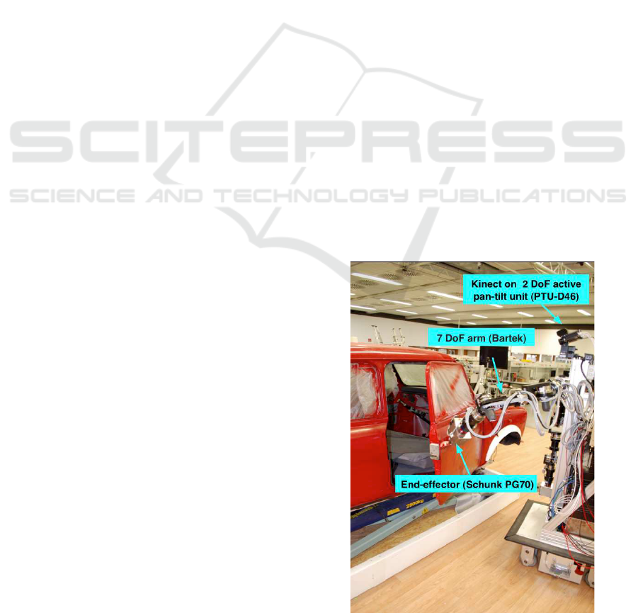
Figure 1: A 7 DoF robotic arm manipulates a car’s door
(single revolute joint articulated object).
taken into account for manipulation. In (Huang et al.,
2012), joint axes’ position of an articulated object is
estimated given different object configurations from
depth image data. This aims at providing the grasp-
253
Wang W., Koropouli V., Lee D. and Kühnlenz K..
Articulated Object Modeling based on Visual and Haptic Observations.
DOI: 10.5220/0004280902530259
In Proceedings of the International Conference on Computer Vision Theory and Applications (VISAPP-2013), pages 253-259
ISBN: 978-989-8565-48-8
Copyright
c
2013 SCITEPRESS (Science and Technology Publications, Lda.)
Vision
data
Frame 1
Frame 2
Articulated object
skeletonization
Check whether single
or multi joint object
Kinesthetic teaching
for object manipulation
Joint type
recognition
Joint
localization
Haptic learning
for manipulation
Joint state-dependent
manipulation behavior learning
Frame N
Articulated
object model
Task execution
Vision data
(current frame)
Object joint state
estimation
Task goal
Articulated Object Model Building
Object Recognition for Manipulation
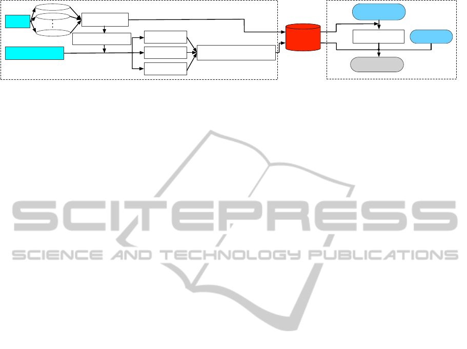
Figure 2: Proposed framework.
ing point and position trajectory to the robot. How-
ever, recognition of the object configuration is not
considered. All previous works lack a framework for
recognition of different articulated objects. In addi-
tion, they do not allow to estimate the current joint
states of the object and adapt the manipulating behav-
ior accordingly. In addition, previous works do not
account for learning the force that is required to op-
erate an object. For example, opening a completely
closed or semi-closed door are two different tasks
which require different manipulating forces. Some
other works focused on learning manipulation of ar-
ticulated mechanisms by learning force control skills
while ignoring the mechanism structure of the ob-
ject. In all these works (Kalakrishnan et al., 2011),
(Lutscher et al., 2010), no visual information is used
to recognize the object and characterize the number
and type of joints and the constraints that apply on
each joint of the object. Therefore, these approaches
cannot generalize to the objects with different struc-
tures or configurations.
All works on articulated objects so far focus, ei-
ther on using visual data for object characterization
without learning manipulation force, or on learning
manipulation force skills without analyzing the artic-
ulation characteristics of the object. Learning manip-
ulation of even a single-joint articulated object is a
challenging problem, since the articulation character-
istics of the object have to be extracted first before
appropriate manipulation force is learned. We thus,
first seek to solve the problem for single-joint articu-
lated objects and extend in future works to multiple-
joint objects. In this paper, a framework for learning
manipulation skills for single-joint articulated objects
is proposed, which consists of (a) skeletonization of
object, (b) joint number estimation based on object
skeleton trace from different visual frames, (c) char-
acterization of joint type, and (d) learning of Carte-
sian force which is required for manipulation. In
particular, visual data are employed to build the ob-
ject skeleton and estimate the current state of the ob-
ject’s joint. The trace of the skeleton nodes over time
is employed to determine whether it is a single- or
multi-joint object. In addition, haptic data in the form
of Cartesian-space forces are captured from multiple
human demonstrations by kinesthetic teaching and
learned in object’s joint state space. Generalization of
manipulation force can be realized based on current
joint’s state and the task goal.
This paper is organized as follows. In Section
2 We define our problem and propose a method for
skeletonize an articulated object and learning the ma-
nipulation force. In Section 3, the experimental setup
and results are presented.
2 PROPOSED APPROACH
To manipulate articulated objects, information about
both the structure and the kinematic and dynamic
properties of the object is required. An articulated
object could be described by its number and type of
joints, link properties and kinematic relationships be-
tween neighboring links. Basic geometry features
which are used for rigid object modeling and recog-
nition, such as Viewpoint Feature Histogram (VFH)
(Rusu et al., 2010), are not suitable for deformable
objects. However, these approaches require complete
depth information of the object. Since articulated ob-
jects can lie in a practically huge number of different
configurations, capturing information about all these
potential configurations is practically infeasible. For
this reason, object skeletonization is the most suit-
able method for extracting the structure and kinematic
constraints of an object. We define the model of an ar-
ticulated object as
Obj = (S, J
m
(T, P, C), f
f
f),m = 1,..,M (1)
where S represents the skeleton of the object which
is used for object recognition, J
m
joint descriptor of
the m-th joint, T joint type, P joint position and C
joint constraints. The f
f
f(J
1
,...,J
M
) is the Cartesian
force which is needed to manipulate the object where
J
1
,...,J
M
are joint descriptors of the articulated object
where M is the number of joints.
Investigating multiple-joint objects is highly com-
plicated and implies sufficient modeling of all indi-
vidual joints of the object. For this, in this paper, we
focus on modeling of single-joint articulated objects
where visual and haptic information is integrated for
VISAPP2013-InternationalConferenceonComputerVisionTheoryandApplications
254
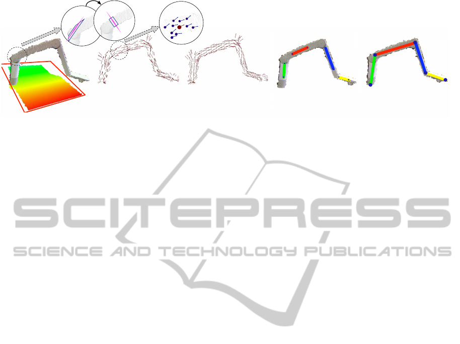
Vector field smoothing based on
Gaussian-weighted nearest neighbors
c) Line shape skeleton extraction
based on vector field clustering
d) Skeleton topology estimation
based on the line growth
e)Object extraction based on
RANSAC plane estimation
a) Vector field generation based
on optimized cutting plane
b)
iteration# n
iteration# 0
Figure 3: Skeletonization steps of a multi-joint articulated object (phone arm).
highly efficient object manipulation. The framework
presented here can be extended to modeling multiple-
joint objects though and this is going to be presented
in future work. Manipulation force constitutes part
of an object’s model since it indicates the dynamic
properties of the object. This force is critical to the
success of a robotic task and depends on the object’s
current joint states. The manipulating force can be
represented by f
f
f = π(s
J
m
, e), m = 1,..., M, where π
is a force generation policy, s
J
m
the state of the m-
th joint which may represent the angle of a rotational
joint or length of a prismatic joint and e the task goal.
Fig. 2 shows the framework which is used to
model a single-joint articulated object. The frame-
work consists of two main components which are
building a database of articulated objects’ models and
recognizing an incoming object based on visual and
haptic information. The modeling stage can be di-
vided into two parts where the first part involves
vision-based object skeleton extraction and the sec-
ond part consists of identification of the object’s dy-
namic properties by teaching the robot appropriate
force to operate the object. The kinematic joint prop-
erties (T,P,C) of a joint J are estimated from obser-
vation of the skeleton S across multiple configura-
tions. Using learning by demonstrations, the appro-
priate force f
f
f is learned in the object’s joint space.
During generalization, the robot observes the object
and extracts its current joint state. The force is gen-
erated based on the task goal such as the position or
joint angle the object should finally reach and its cur-
rent joint state.
2.1 Object Skeletonization
A point cloud, in terms of depth image data of an ob-
ject, is used for skeletonization of the articulated ob-
jects. This is realized by observing multiple frames
of the object’s kinematic links. The skeleton of the
object is extracted which allows to recognize the ob-
ject and estimate its current joint states. Based on
extracted object skeleton and the location of skeleton
nodes, the object is classified as a single or multi-joint
object. Skeleton models which represent the medial
axis of a 3D model are widely used for object recon-
struction and arterial object analysis. In (Tagliasacchi
et al., 2009), rotational symmetry axis is used for the
object skeleton points estimation. This work requires
the full range point cloud of the object and uses the as-
sumption that all object’s model should be pipe-like.
Instead, in this paper, a novel method of skeletoniza-
tion of articulated objects is presented, which is not
based on pipe-like configurations only but it can iden-
tify objects of abstract structures such as plane-like
structure. The phone arm shown in Fig. 3 and car’s
door shown in Fig. 5 are two examples of objects
with different type of structure, the first pipe-like and
the latter plane-like.
2.1.1 Vector Field Generation
Firstly, the Random sample consensus (RANSAC)-
based plane fitting algorithm is used to extract the
object point cloud from the background (Rusu et al.,
2010), shown in Fig. 3(a) and Fig. 5(b). The vec-
tor field presents the best local rotational symmetry
of each point in the extracted object point cloud. Our
method extracts the vector field using the optimized
cutting plane. Based on RANSAC plane estimation
with a certain number of iteration steps T
c
, the vector
field over the data points is generated. The best cut-
ting plane C
c
= plane[x
i
,v
i
] which goes through the
point x
i
with the normal ˆv is estimated by minimizing
the number of inliers which are within the distance d
c
.
In addition, these points should also be in the same
cluster N
i
of the related point x
i
using the geometric
nearest neighbors:
ˆv
i
= argmin
v∈ℜ
3
,kvk=1
num({j
N
i
| k c
j
−C
(t)
c
k≤d
c
;x
j
∈X
raw
}),
where t ∈[1,T
c
] is the iteration index. Fig. 3(b) shows
the result where the circles show the iteration step.
ArticulatedObjectModelingbasedonVisualandHapticObservations
255

X(m)
Y(m)
Z(m)
Frame #1
Frame #2
Frame #3
Frame #4
Frame #5
Frame #6
Frame #7
Frame #8
Frame #9
Frame# 10
Frame #11
Skeleton Node #1
Skeleton Node #2
Skeleton Node #3
Skeleton Node #4
Skeleton Node #5
Figure 4: Skeleton node traces through different visual
frames: black lines present the skeleton topology; each
skeleton node trace is shown by a different-color solid line.
Note that, the direction of the optimized cutting plane
could be the inverse which, however, will not influ-
ence the final results. The directions are reorganized
based on the base plane coefficients.
A Gaussian-weighted method is developed for the
vector field smoothing. The point x
i
with normal
v
i
has the neighbor cluster X
i
with points number n,
which is determined by the distance threshold d
s
. The
weight function w is defined based on the gaussian
contribution, decided by each neighbor’s3-D distance
respect to the point x
i
:
w
j
=
1
√
2πσ
2
exp(−
1
2σ
2
kx
j
−x
i
k
2
),
v
i:new
=
∑
n
j=1
w
j
v
j
∑
n
j=1
w
j
, x
j
∈X
i
.
(2)
In our case, the standard deviation σ = 1 is used. Fig.
3(c) and Fig. 5(c) shows the smoothed vector fields
over the object in different shapes.
2.1.2 Line-shape Skeleton Estimation
The skeleton of the object is described with the
lines and linked nodes named skeleton nodes. Af-
ter smoothing, the vector field is clustered using
the nearest neighbor clustering method (Wang et al.,
2011), which considers the positions and the direc-
tions. Meanwhile, the final skeletal point position
could be extracted using the centering of the raw
object points, which should be in the cutting plane
through the related vector point with distance thresh-
old. These skeletal points could be extracted from pla-
nar object. Instead, (Tagliasacchi et al., 2009) mini-
mize the sum of squared distances from the point to
the related normals, which will cause the position of
the skeletal points for the planar object become infi-
nite. The best line l could be extracted to minimize
the distance sum from the extracted skeletal points.
The line detection result is shown in the Fig. 3(d).
2.1.3 Skeleton Topology Extraction
The line detection result presented in Fig. 3(d), does
not constitute the whole skeleton of the object since
some skeleton points have been filtered out by clus-
tering step. For this, the line growth algorithm is used
to estimate the whole skeleton topology. All the de-
tected lines grow in both positive and negative direc-
tion to overcome the whole skeleton. The lines stop
growing when they,
(i) reach the edge of the object point cloud and are
viewed as skeleton root node as the Node 1 and
Node 5 in Fig. 4;
(ii) meet another skeleton line and at that time they
stop growing up and are characterized as skeleton
link node as the Node 2, 3 and 4 in Fig. 4.
These points are clustered and merged using 3-D Eu-
clidean clustering (Wang et al., 2011). Then whole
object skeleton nodes are extracted. Meanwhile the
root and link nodes indicate the topology of object
skeleton. The results are shown in Fig. 3(e) and Fig.
5(c). Different colored points represent the different
estimated skeleton nodes and the dashed line links
represents the skeleton topology.
2.1.4 Kinematic Joint Number Determination
As shown in Fig. 4 and Fig. 5(d), the object skeleton
topology is extracted frame by frame with different
configurationsof articulated objects. The dashed lines
represents the object skeleton topology and the traces
of different extracted skeleton nodes are shown as dif-
ferent colored solid line. With the traces of skeleton
nodes with different frames, all the dynamic obser-
vations are obvious. From frames 1 to 8, it is ob-
vious that the observation patterns of nodes 3 to 5
differ from the patterns from frame 8 to 11. These
two kinds of patterns in terms of the skeleton topol-
ogy of object are changing, imply that the estimated
object is not the single joint articulated object. The
skeleton node S
i
with index i is viewed as the base
node to estimate the Euclidean distances with others
as E
i
= kS
0
− S
i
k,i ∈ [1, n], which is used to calcu-
late the difference cost function DIF
j
between current
frame j with the previous frame j −1 as following:
DIF
j
=
n
∑
i=1
|E
j
i
−E
j−1
i
|
E
j−1
i
, j ∈ [1, F] (3)
VISAPP2013-InternationalConferenceonComputerVisionTheoryandApplications
256

where F is the number of frames. At the frame 9,
DIF
9
increased significantly, which means this artic-
ulated object contains multi kinematic joints. In com-
parison, as shown in Fig. 5(d), the door of car is the
single joint articulated objects.
With the certification of the joint number from
the object skeleton topology observations of different
demonstrations, the kinematic joint characterization
and localization could be extracted in the different
strategies. As the one joint articulated object, the tra-
jectory from one of object skeleton nodes could rep-
resent the whole object motion pattern and be used
for its kinematic joint characterization. Otherwise,
for multi joint articulated object, we need to analyze
all the skeleton nodes trajectories hierarchically to ex-
tract all the kinematic joints’ properties.
2.2 Kinematic Joint Characterization
The kinematic joints of the articulated object are
distinguished into two types, prismatic and revolute
(Sturm et al., 2011). Given the positional trajec-
tories of the end-effector of the object, it is rather
straightforward to discriminate between the two types
of joints. The position vector of the point A of an ar-
ticulated object which is moving in the 3D space can
be expressed by ~g = g
x
ˆx+ g
y
ˆy+ g
z
ˆz. If only one po-
sitional component is non-zero, the joint is prismatic.
The positional components are digitized as follows:
if a component is different than zero, it is assigned
the value 1, else the value 0. The digitized compo-
nents g
x
, g
y
and g
z
can the input to a Boolean logic
scheme which is equivalent to the numerical compu-
tation given by
Y = (g
x
+ g
y
+ g
z
−g
x
g
y
g
z
)(g
x
+ g
y
−g
x
g
y
). (4)
By applying (4) at each time step and taking the av-
erage
¯
Y of all outputs Y(n) where n is the time in-
dex, we deduce whether the joint is revolute or pris-
matic. If
¯
Y = 0 then the joint is prismatic. If
¯
Y 6= 0,
the joint is revolute. In case that a joint is revo-
lute, and thus, causes a rotational movement, the an-
gle range of the joint is estimated. The positional
data of the end-effector of an articulated object are
recorded during demonstrations of the task. The an-
gle range is computed by θ(n) = arctan( ¯g
i
(n)/ ¯g
j
(n)),
where n = 1, ...,N is the time index and ¯g
i
and ¯g
j
the
two non-zero average positional trajectories in direc-
tions i and j. The average positional trajectories are
computed, since many demonstrations are available,
as ¯g
i
(n) =
1
K
∑
K
1
g
(k)
i
, ¯g
j
(n) =
1
k
∑
K
1
g
(k)
j
, where g
(b)
a
is
the position of demonstration b in direction a and K
is the number of demonstrations of the task.
2.3 Learning Force Skills
We desire to extract an average expert behavior for a
task based on multiple demonstrations (Lee and Ott,
2011). Since the speed of the demonstrator varies
from trial to trial and demonstrations are not time-
aligned, demonstrations become time-aligned by Dy-
namic Time Warping. The force policy of a task is
extracted from multiple demonstrations using a prob-
abilistic approach proposed in (Calinon et al., 2007).
This approach consists of Gaussian Mixture Model-
ing and Regression and estimates a smooth general-
ized version of demonstrated signals which captures
all the important features of the task.
Time-aligned data pairs d
i
= {s
i
, f
f
f
i
}, i = 1,..., N
are considered, where N is the number of data points
in each demonstration, s
i
the input joint states and
f
f
f
i
∈ ℜ
D×N
represent force data where D is the di-
mensionality of f
f
f. A mixture of L Gaussian func-
tions is considered with probability density function
p(d
i
) =
∑
L
l=1
p(l)p(d
i
|l), where p(d
i
|l) is a condi-
tional probability density function and p(l) = π
l
is the
prior of the l-th distribution. We model the mapping
from joint angles to endpoint forces by a mixture of L
Gaussian functions. It is
p(d
i
|l) =
1
p
(2π)
D
|Σ
l
|
exp(−
1
2
(ξ
i
−µ
l
)
T
Σ
−1
l
(ξ
i
−µ
l
)
)
where {π
l
,µ
l
,Σ
l
} is the Gaussian function’s parame-
ter set represented by the prior probability, the mean
and covariance matrix. The parameters of the mixture
are estimated using the Expectation-Maximization
(EM) algorithm. Following learning of the mixture
parameters, a generic form of the signals f
f
f
i
is recon-
structed using Gaussian Mixture Regression (GMR).
The states s
i
are employed as inputs and the output
vectors
ˆ
f
i
are estimated by regression. The mean and
covariance matrix of the l-th Gaussian component are
defined as
µ
l
= {µ
s,l
, µ
f,l
}, Σ
l
=
Σ
s,l
Σ
sf,l
Σ
fs,l
Σ
f,l
.
The conditional expectation and covarianceof the sig-
nal f
f
f
l
given s are
ˆ
f
l
= µ
f,l
+ Σ
fs,l
(Σ
s,l
)
−1
(s −µ
s,l
),
ˆ
Σ
f,l
= Σ
f,l
− Σ
fs,l
(Σ
s,l
)
−1
Σ
sf,l
. Finally, the condi-
tional expectation and covariance of f
f
f given s for
a mixture of K Gaussian components are defined
by
ˆ
f =
∑
L
l=1
β
l
ˆ
f
l
,
ˆ
Σ
f
f
f
= Σ
L
l=1
β
2
l
ˆ
Σ
f,l
, where β
l
=
p(s|l)/
∑
L
j=1
p(s|j) is the responsibility of the l-th
Gaussian for s
i
. The task force profile f
f
f is learnt in
the joint space s which is represented by the angle θ.
3 EXPERIMENTAL RESULTS
This paper focuses on skeletonization and manipulat-
ArticulatedObjectModelingbasedonVisualandHapticObservations
257
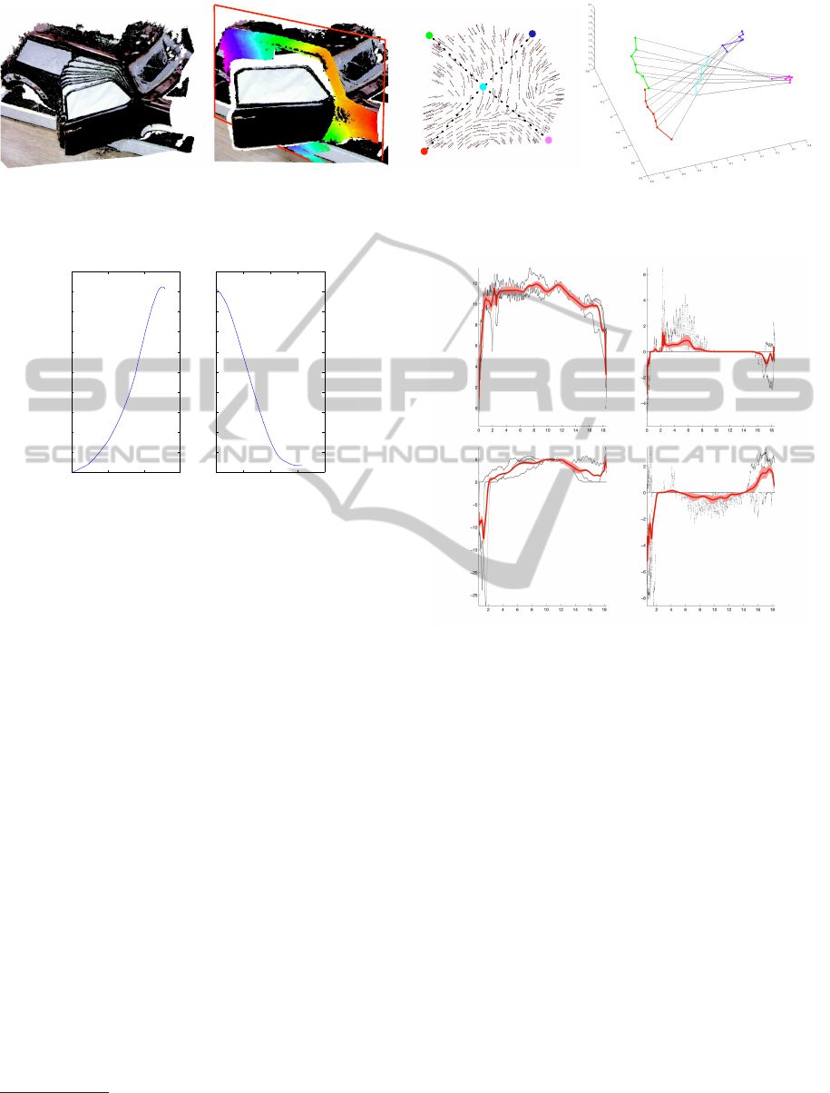
Data acquirement with
different configurations
a)
Object extraction based on
RANSAC plane estimation
b)
Vector field and
extracted skeleton topology
c)
Y(m)
5 Skeleton Nodes
7 Frames
X(m)
Z(m)
Skeleton node trace through
different frames
d)
Figure 5: Skeletonization of a car door which has a single revolute kinematic joint.
0 2000 4000 6000
0
2
4
6
8
10
12
14
16
18
20
0 1000 2000 3000 4000
0
2
4
6
8
10
12
14
16
18
20
Door opening
Door closing
Joint angle
Time stepTime step
Figure 6: Angle state space estimated based on the position
of the car’s door handle. The joint angles are expressed in
degrees. The time step is equal to 1ms.
ing a single-joint articulated object. We demonstrate
the performance of proposed method in a pitstop sce-
nario where the single-joint car door is to be recog-
nized and manipulated. A model of the door, rep-
resented by (1), is built which contains the skeleton
topology, the kinematic descriptor of the door’s joint
and the end-effector force required for manipulation.
The point cloud of the door is acquired by one
Kinect
1
sensor which is mounted on the top of the
robot, shown in Fig. 1. This data is used for skele-
tonization of the door and estimation of the skele-
ton node traces over different frames, shown in Fig.
5. The skeletonization of object is realized partially
based on the Point Cloud Library
2
. We desire to learn
manipulation skills in terms of the force which is re-
quired to open or close this single-joint car door.
Appropriate force is demonstrated to the robot
by kinesthetic teaching and learned from multiple
demonstrations of a task using the proposed ap-
proach. Several demonstrations of a door-opening-
and-closing task are provided to a 7 DoF robotic arm.
Task space force as well as end-effector positional
trajectories are captured during demonstrations. Fol-
lowing task space force learning, generalization is re-
1
http://www.primesense.com
2
http://www.pointclouds.org
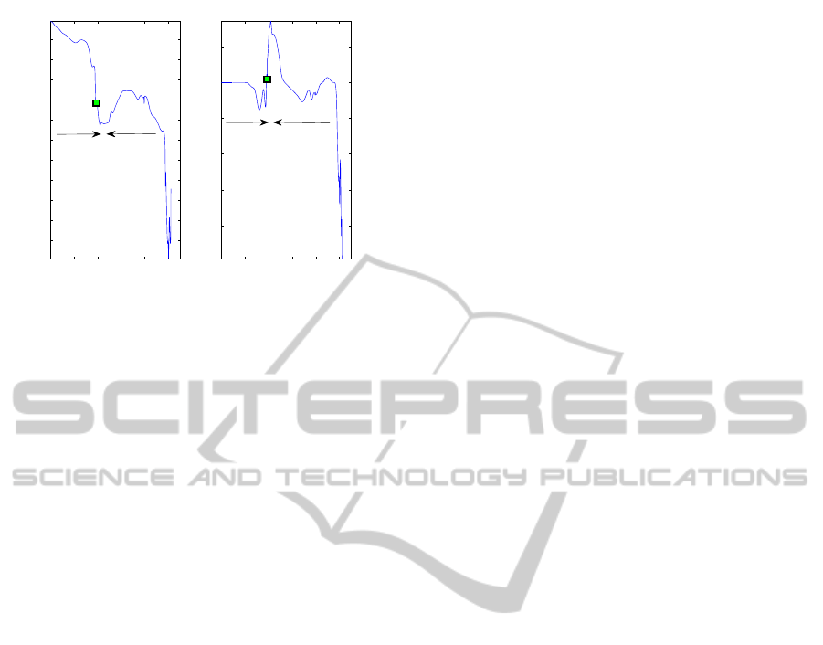
(a)
(b)
Angle (degrees) Angle (degrees)
Fy(N) Fy(N)
Fx(N)Fx(N)
Figure 7: Learning the generalized 2-dimensional force pro-
file of a task in joint angle space given 3 task demonstra-
tions. (a) Door opening, (b) door closing.
quired to situations where the initial door position
may differ and based on the task goal such as open-
ing or closing. To do so, the force constraints of the
task are learnt with respect to door’s joint states. The
current joint states are estimated using current frame’s
visual data.
Skeletonization of the car door is shown in Fig.
5, where the door is recognized as single-joint artic-
ulated object using (3). We observe that the trace of
skeleton node has the same motion pattern with the
robot arm end-effector trajectory. The current door’s
joint state could be achieved by the skeleton topology
position and learned door’s rotational joint model.
Every demonstration consists of a door-opening and a
door-closing phase without any interruption between
the two phases. The different start and end points of
each trial are due to slight sliding movement of the
robot end-effector along the handle of the door. Given
manipulation trajectory, the type of joint is identified
firstly by using the algorithm described in 2.2. The
VISAPP2013-InternationalConferenceonComputerVisionTheoryandApplications
258
0 1000 2000 3000 4000 5000
−10
−8
−6
−4
−2
0
2
4
6
8
10
0 1000 2000 3000 4000 5000
−4
−3
−2
−1
0
1
TimestepTimestep
F
x
(N)
F
y
(N)
Open
Open
Close
Close
Figure 8: Door opening and closing where the door is ini-
tially open at 8 degrees. The time step is equal to 1ms.
door’s joint is characterized as revolute and estimate
the joint space constrains which is computed, see Fig.
6. This angle space constitutes the input state space in
terms of which the force trajectories are learned from
multiple demonstrations. Fig. 7 shows learning of the
2-dimensional force for a door opening-closing task
from 3 demonstrations by using the method described
in Section 2.3. The force is learned separately for the
two phases of the task. Following learning, we desire
to generalize the force generation policy to different
tasks with different current state. More specifically,
the case is considered where the car door is already
open at 8 degrees and the force profile is estimated
which needs to be exerted in order to open the door
completely and close it afterwards. Fig. 8 shows the
generalized force for this task where the two phases,
opening and closing.
4 CONCLUSIONS
In this paper, we propose a method for articulated ob-
ject modeling by combining visual and haptic data.
Visual processing contributes to recognizing the ob-
ject and identifying its structure and more specifi-
cally, its skeleton topology, the number and type of
joints as well as the current joint states. Haptic data
represented by force are learned from multiple task
demonstrations in order to be able to operate the ar-
ticulated mechanism. The forces are encoded with
respect to joint states so that the system can gener-
alize to new situations where the initial object con-
figuration, and thus, joint state differs. The proposed
method is demonstrated in manipulation of a single-
joint car door. Future work will focus on modeling
of a wide-variety of objects which also involve more
than one joint.
ACKNOWLEDGEMENTS
This work is supported in part by the DFG excel-
lence initiative research cluster ”Cognition for Tech-
nical Systems – CoTeSys,” see www.cotesys.org, the
FP7 EU-STREP ”Interactive Urban Robot (IURO)”,
see www.iuro-project.eu, the Institute for Advanced
Study (IAS), Munich, and the China Scholarship
Council (CSC), see http://en.csc.edu.cn.
REFERENCES
Calinon, S., Guenter, F., and Billard, A. (2007). On learn-
ing, representing, and generalizing a task in a hu-
manoid robot. Systems, Man, and Cybernetics, Part
B: Cybernetics, 37(2):286–298.
Huang, X., Walker, L., and Birchfield, S. (2012).
Occlusion-aware reconstruction and manipulation of
3d articulated objects. In In Proc. of the IEEE In-
ternational Conference on Robotics and Automation
(ICRA), pages 1365–1371, St. Paul, Minnesota.
Kalakrishnan, M., Righetti, L., Pastor, P., and Schaal, S.
(2011). Learning force control policies for compli-
ant manipulation. In Intelligent Robots and Systems
(IROS), pages 4639–4644.
Katz, D. and Brock, O. (2008). Manipulating articulated
objects with interactive perception. In In Proc. of the
IEEE International Conference on Robotics and Au-
tomation (ICRA), pages 272–277, Pasadena, CA.
Lee, D. and Ott, C. (2011). Incremental kinesthetic teaching
of motion primitives using the motion refinement tube.
Autonomous Robots, 31(2):115–131.
Lutscher, E., Lawitzky, M., Cheng, G., and Hirche, S.
(2010). A control strategy for operating unknown
constrained mechanisms. In In Proc. of the IEEE In-
ternational Conference on Robotics and Automation
(ICRA), pages 819–824, Anchorage, Alaska, USA.
Rusu, R. B., Bradski, G., Thibaux, R., and Hsu, J. (2010).
Fast 3d recognition and pose using the viewpoint fea-
ture histogram. In In Proc. of the International Con-
ference on Intelligent Robot Systems (IROS), pages
2155–2162, Taipei, Taiwan.
Sturm, J., Stachniss, C., and Burgard, W. (2011). A prob-
abilistic framework for learning kinematic models of
articulated objects. Journal of Artificial Intelligence
Research, 41(2):477–526.
Tagliasacchi, A., Zhang, H., and Cohen-Or., D. (2009).
Curve skeleton extraction from incomplete point
cloud. In ACM Trans. on Graph, 28(3):71.
Wang, W., Brˇsˇci´c, D., He, Z., Hirche, S., and K¨uhnlenz,
K. (2011). Real-time human body motion estimation
based on multi-layer laser scans. In In Proc. of the
International Conference on Ubiquitous Robots and
Ambient Intelligence, pages 297–302, Incheon, Korea.
ArticulatedObjectModelingbasedonVisualandHapticObservations
259
