
A GPU-based Method for Generating quasi-Delaunay Triangulations
based on Edge-flips
Cristobal A. Navarro
1
, Nancy Hitschfeld-Kahler
1
and Eliana Scheihing
2
1
Department of Computer Science, FCFM, Universidad de Chile, Santiago, Chile
2
Instituto de Inform´atica, Universidad Austral de Chile, Valdivia, Chile
Keywords:
Delaunay Triangulations, Edge-flip Technique, Parallel Realtime Applications, CUDA, OpenGL, GPGPU.
Abstract:
The Delaunay edge-flip technique is a practical method for transforming any existing triangular mesh S into
a mesh T(S) that satisfies the Delaunay condition. In this paper we present an iterative GPU-based method
capable of improving triangulations under the Delaunay criteria. This method is based on the edge-flip tech-
nique and its implementation is fully integrable with the OpenGL rendering pipeline. Since the algorithm uses
an ε value to handle co-circular or close to co-circular point configurations, we can not guarantee that all trian-
gles fulfill the Delaunay condition. However, we have compared the triangulations generated by our method
with the ones generated by the Triangle software and by the CGAL library and we obtained less than 0.05%
different triangles. Based on our experimental results, we report speedups from 14× to 50× against Lawson’s
sequential algorithm and of approximately 3× against the O(nlog n) CGAL’s and Triangle’s constructive
algorithms while processing bad quality triangulations.
1 INTRODUCTION
The Delaunay triangulation T of a point set P is the
triangulation that maximizes the smallest angle over
all triangulations of P. Numeric computations on this
kind of triangulation is known to be more precise
than in the other ones (De Berg, 2000). Good qual-
ity meshes are needed in many applications such as
scientific simulations, terrain rendering, video-games
and medical 3D reconstruction, among others.
Delaunay triangulations can be achieved in two
ways: (a) by creating them from a PSLG (Planar
straight linear graph), or (b) by transforming an al-
ready existing triangulation into one that satisfies the
Delaunay condition. In general, in the case (a), a De-
launay triangulation is generated for the set of points
of the PSLG. The segments (boundary edges) are
then inserted to generate either a constrained Delau-
nay triangulation or a conforming Delaunay triangu-
lation (Shewchuk, 1996). Case (b) assumes that a
triangulation is given as input and the mesh needs
to be transformed into a Delaunay mesh. A known
technique for making this transformation is to flip
the edges that do not satisfy the Delaunay condition.
The edge-flip technique was first introduced by Law-
son (Lawson, 1972) and the proposed sequential al-
gorithm has a worst-case complexity O(n
2
), where n
is the number of points of the triangulation (Fortune,
1993; Edelsbrunner, 2001).
Real-time applications cannot make use of se-
quential algorithms when handling meshes close to
a million triangles. To achieve faster computations,
parallel solutions are needed. In recent years, GPU
computing has become an important research area for
parallel computing due to its high performance and
low cost. Several applications that require geometric
modeling and visualization benefits strongly from the
use of a GPU. In particular, the generation of Delau-
nay triangulations with a fast GPU-based method is
today a topic of research.
The main contribution of this paper is the design
and implementation of an iterative GPU-based al-
gorithm that generates quasi-Delaunay triangulations
starting from any existing triangulation. The algo-
rithm maps threads to edges. Each thread is responsi-
ble for checking one edge Delaunay condition, doing
one edge-flip and updating one edge data inconsis-
tency if necessary. The performance and the qual-
ity of the generated meshes is compared with two
well known and efficient sequential constrained De-
launay algorithms: the algorithm inside the software
Triangle (Shewchuk, 1996) and the algorithm avail-
able in the CGAL library (CGAL, 2012). As test
examples we used bad quality triangulations (with
27
Navarro C., Hitschfeld-Kahler N. and Scheihing E..
A GPU-based Method for Generating quasi-Delaunay Triangulations based on Edge-flips.
DOI: 10.5220/0004281900270034
In Proceedings of the International Conference on Computer Graphics Theory and Applications and International Conference on Information
Visualization Theory and Applications (GRAPP-2013), pages 27-34
ISBN: 978-989-8565-46-4
Copyright
c
2013 SCITEPRESS (Science and Technology Publications, Lda.)
minimum angles close to 0), with mesh sizes rang-
ing from 100 thousand up to 5 millions points. We
are not using exact predicates nor floating point filters
because these techniques can not be efficiently imple-
mented on GPU architectures without sacrificing per-
formance. These techniques would require adding if-
else conditionals and handle irregular-dataaccess pat-
terns. That is why, in favor of speed, some results are
quasi-Delaunay triangulations and not fully Delaunay
triangulations.
In principle, the comparison of a transformation
algorithm that generates quasi-Delaunay triangula-
tions, as the proposed in this paper, with respect to
constructive ones that generate exact Delaunay trian-
gulations such as CGAL and Triangle can seem un-
fair because they solve different problems. However,
since the complexity of a constructive algorithm is
O(nlog n) and the Lawson algorithm is O(n
2
), many
times it is preferred to build the Delaunay mesh from
scratch instead of improving an existing one. In some
way, this research is intended to show that a parallel
method based on edge-flips can become fast and use-
ful in practice for applications that not require exact
Delaunay meshes.
The paper is organized as follows: Section 2
presents our data structures and how they are com-
patible with OpenGL. Sections 3 and 4 cover the al-
gorithm and implementation details. Section 5 shows
experimental results with 2D random inputs and 3D
surface triangulations. Section 6 describes some re-
lated work and the similarities and differences with
other GPU-based approaches. Finally, section 7 con-
cludes our work.
A preliminary and short version of this paper was
presented at the EuroCG11 workshop (Navarro et al.,
2011).
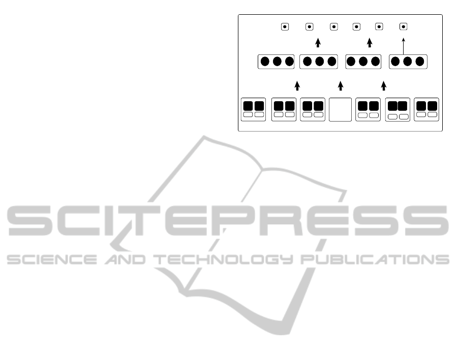
2 DATA STRUCTURES
Proper data structures have been defined to efficiently
represent a triangulation on the GPU. This representa-
tion is inspired by the Dynamic Render Mesh (Tobler
and Maierhofer, 2006). Figure 1 illustrates the three
main components: Vertices, Triangles and Edges.
Vertices are represented with a one-dimensional
array in the same way as the OpenGL VBO (Ver-
tex buffer object). Each position is of the type (x,y)
or (x,y,z) depending on the used spatial dimension.
The Triangles array is a set of indices to the Ver-
tices array. For each three consecutive indices, a
triangle is defined. Each edge of the Edges array
contains a pair of indices v
1
, v
2
to the Vertices ar-
ray and two pairs of indices t
a
= {t
a
1
,t
a
2
} and t
b
=
t0
Surface Mesh S
Edges
Triangles
Vertices
p-2...
t1
A
0
n-2
0 2 4
A C B C
0
ta tb
tm-1
3m-3 3m-2 3m-1
A B C
...
n-1
...
... ... ...
A B C
tbta
1 2
B
v1 v2
v1 v2
1
ta tb
v1 v2
2
ta tb
v1 v2
p-3
ta tb
v1 v2
p-1
ta tb
v1 v2
51 3
Figure 1: Data structures for mesh rendering/processing.
{t
b
1
,t
b
2
} to the Triangles array (for boundary edges,
t
b
remains unused). This way, an edge can know
its endpoint indices directly through v
1
, v
2
or in-
directly via the pairs {Triangles[t
a
1
],Triangles[t
a
2
]}
and {Triangles[t
b
1
],Triangles[t
b
2
]}. This redundant
information becomes useful for checking neighbor-
hood consistency after each flip. In addition, indices
to the opposite vertices per edge are stored in the
Opposites array in order to speed up angle computa-
tions (boundary edges have only one opposite vertex).
This data model can be naturally implemented and in-
tegrated with the OpenGL API and CUDA (Nvidia,
2011) or OpenCL. It is important to mention that for
rendering, only the Vertices and Triangles arrays are
accessed by the graphics API; the Edges and the Op-
posites arrays are for efficiently accessing neighbor
information. All mentioned arrays use Θ(n) of mem-
ory space, where n is the number of points.
3 ALGORITHM OVERVIEW
The algorithm we propose is iterative. In each iter-
ation, two consecutive phases of parallel computing
are executed:
• Phase 1: Detection, exclusion & processing.
• Phase 2: Repair.
On each iteration the algorithm transforms the
mesh a step closer to the Delaunay mesh. The
algorithm finishes when the Delaunay triangulation
is reached. The following sub-sections explain the
phases in more detail.
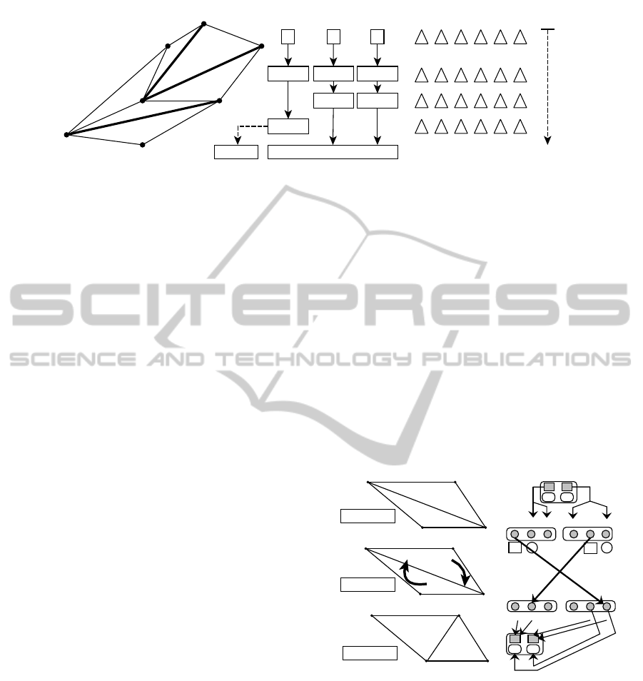
3.1 Detection, Exclusion and Processing
This phase is in charge of three steps: (1) detection of
edges that do not fulfill the Delaunay condition, (2)
exclusion of edges that can not be flipped in parallel
and (3) processing the edges that can be flipped in par-
allel. Our algorithm maps threads to edges by using
GRAPP2013-InternationalConferenceonComputerGraphicsTheoryandApplications
28
T
0
T
1
T
2
T
5
T
4
T
3
a cb
ex(T1) ex(T3) ex(T5)
ex(T2)
ex(T2) ex(T4)
selected subsetexcluded
T
0
T
1
T
2
T
3
T
4
T
5
b ca
ba b cc
ba b cc
F[] array
a
b
c
t
Figure 2: Exclusion mechanism. Each thread performs an atomic operation ex(T
i
) to select its triangles. The F array has the
information of which thread has taken a given triangle.
the PRAM model in such a way that thread t
i
handles
edge e
i
with i ∈ [0, ne−1] (ne is the number of edges).
The execution threads detect first the edges that need
to be flipped (bad edges), then they go through a fil-
ter where only the independent threads survive and
finally, the survivors flip their edge.
For the detection step, threads test their corre-
sponding edge e against the Delaunay condition by
computing the opposite angles λ and γ of e using the
information from t
a
, t
b
. The test must satisfy the fol-
lowing condition:
λ+ γ ≤ π (1)
If the test of equation (1) fails, the edge is a bad edge
and needs to be flipped. On the other hand, if the test
passes, the execution thread ends. Most of the time it
is not possible to flip the complete set of bad edges in
one iteration because the flip of a given edge e com-
promises the consistency of the neighbor edges that
belong to t
a
and t
b
. However, it is possible to pro-
cess a subset A of the edges that satisfy the following
condition:
∀e
1
,e
2
∈ A T
e
1
∩ T
e
2
=
/
0; T
e
= {t ∈ T : e ∈ t} (2)
For implementing the exclusion step, the algo-
rithm internally uses a Flags array where Flags[i] ==
Taken if the i-th triangle was flagged by a thread, and
Flags[i] == Free if it was not. Each thread that needs
to flip an edge requires two flags to be set, the ones
associated with the triangles that share its edge. This
operation is done atomically (atomic operations are
sequential only when two or more threads access the
same memory location). When a thread flags the first
triangle, some neighbor threads will be excluded (i.e
the ones that failed to catch this flag). When a thread
flags the second one, the rest of the neighbors will get
excluded. Figure 2 shows an example, where edges
a,b and c need to be flipped but only {a,c} or {b,c}
can be processed at the same time. By using condition
(2), the thread associated with edge a is excluded.
For the processing step, the per thread edge-flip
method is designed as a swap of indices between the
associated triangles t
a
, t
b
making a rotating effect of
the triangles (see Figure 3). For a given edge e
i
, our
parallel edge-flip proceeds in the following way:
1. Variables: O[] = Opposites, T[] = Triangles,
E[] = Edges;
2. Get the opposite vertex indices o
1
,o
2
:
o
1
= O[i][0]; o
2
= O[i][1];
3. Get c
1
∈ t
a
,c
2
∈ t
b
such that v
1
= T[c
1
],v
2
= T[c
2
]:
c
1
= E[i].t
a
1
; c
2
= E[i].t
b
2
;
4. do the edge-flip:
T[c
2
] = T[o
1
]; T[c
1
] = T[o
2
];
5. Update t
a
,t
b
and v
1
,v
2
:
E[i].t
a
= [o
1
,c
1
]; E[i].t
b
= [c
2
,o
2
];
E[i].v
1
= E[i].t
a
1
; E[i].v
2
= E[i].t
b
2
;
T
0
T '
0
T '
4
T
e
131
0
2
3
o1
1
0
2
3
1
0 21 3 5
0 32
0 21
1 2
3 54
c2
ta
0 2
tb
e
ta
1 3
tb
T
0
T
1
0 1
0
1
T
0
T
1
0
2
3
1
T
0
T
1
before
after
rotation / flip
o2
32
c1
e
e
e
Figure 3: Visual example of edge-flip procedure for e.
The steps of this phase are summarized in Figure 4
showing how threads make their way down.
3.2 Repair
After the parallel edge-flips were executed, incon-
sistent information can be stored on neighbor edges.
Some edges can store references to triangles whom
they no longer belong (obsolete t
a
and t
b
pairs). Fig-
ure 5 shows a simple mesh where inconsistent infor-
mation appears at edges d and b after e was flipped.
AGPU-basedMethodforGeneratingquasi-DelaunayTriangulationsbasedonEdge-flips
29
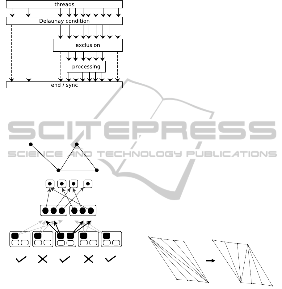
Figure 4: General view of the detection, exclusion and pro-
cessing mechanism. Each block acts as a thread filter.
The information of the new triangles to whom d and
b belong are in the triangles that were rotated while
flipping e.
0
Triangles
Vertexes
1
1
0
0 3 2 0
31 2
2
Edges
a
ta
0
b
ta
0
d
ta
2
e
0 2
c
ta
1 2
3
13
tb
0 1 2 3 4 5
ta
0
2
3
1
T
0
T
1
T T
e
Figure 5: Edges marked with a cross are inconsistent.
Fortunately these inconsistencies can be easily identi-
fied with the following two expressions:
q = |v
1
− t
a
1
| + |v
2
− t
a
2
| (3)
w = |v
1
− t
b
1
| + |v
2
− t
b
2
| (4)
If q > 0 (w > 0) then t
a
(t
b
) needs to be repaired.
The rotation relations are stored at the moment of
flipping an edge e using an array of rotations R[] of
size m (number of triangles). The triangle that rotated
with t
a
and t
b
is t
ra
= R[t
a
1
/3] and t
rb
= R[t
b
1
/3], re-
spectively. Note that the indices stored in t
a
and t
b
point to the Triangles array and each triangle is de-
fined by three consecutive vertex indices.
3.3 Handling Problematic and Worst
Cases
During the first phase, there are two scenarios that re-
quire a more detailed explanation: case (1); the exis-
tence of co-circular configurations and case (2); the
possible existence of dead-locks.
Case (1): if there are co-circular or almost co-circular
configurations, our algorithm could fall into an infi-
nite loop of edge-flips due to floating point errors. We
solve this issue by using a small tolerance value in the
evaluation of condition (1):
λ+ γ ≤ π + ε (5)
This leads to ignoring some flips that in theory,
should have been performed. That is why the gen-
erated triangulations may be quasi-Delaunay triangu-
lations and not fully Delaunay triangulations. The ε
value was experimentally estimated.
Case (2): a dead-lock could occur if there exists a
circular chain of triangles, where all edges must be
flipped and each thread can flag only one of its tri-
angles. This kind of chain can not exist because it
must have at least one edge that fulfills the Delaunay
condition: the smallest edge of the chain. Note that
the triangles that share the smallest edge are free to
be flagged by a neighbor thread. Then, in chains like
these there will always be at least one edge that can
be flipped, therefore a dead-lock will never occur.
The known worst case configuration for Law-
son’s sequential algorithm is the one shown in Fig-
ure 6 (Edelsbrunner, 2001).
Figure 6: One of the worst cases for any edge-flip based
method.
This worst-case triangulation has eight vertices,
thirteen edges and six triangles. The algorithm ex-
ecuted five iterations and the number of flips per it-
eration was {1,2,3,2,1}. As this triangulation gets
larger, the number of triangles increases and the num-
ber of iterations also grows. However, the perfor-
mance of the algorithm is better than the sequential
algorithm, because under the PRAM model the cost
per iteration is Θ(1) as the algorithm can do several
edge flips in parallel. Experimentally, we observed
that for these configurations the number of required
GRAPP2013-InternationalConferenceonComputerGraphicsTheoryandApplications
30
iterations is m − 1, with m the number of triangles.
The amount of edge-flips per iteration increases by
one until the m/2-th iteration. Then, the number of
parallel flips decreases by one until the last iteration is
reached. The computational complexity is O(n) (note
that m = O(n)). This is an improvement over the se-
quential method, which in this case is O(n
2
).
4 IMPLEMENTATION DETAILS
Nvidia’s CUDA architecture and API were chosen to
implement the kernels, while OpenGL was chosen to
render the triangulations. Using C type data struc-
tures for the mesh model, it is possible to represent
vertex and triangle data via the OpenGL buffer ob-
jects: the VBO (Vertex Buffer Object) and EBO (El-
ement array Buffer Object). In addition, CUDA sup-
ports OpenGL interoperability, meaning that threads
can read and write directly into the VBO and EBO ar-
rays. As with the vertices, the edges are also sent to
the GPU at mesh loading time, and they can option-
ally be sent back at the end if needed (for example, to
save the mesh into a file). The exclusion step is han-
dled with atomic operations available from the CUDA
C API. The performance is increased by using loop
unrolling, coalesced memory on per edge data, mini-
mal branching, constant types and shared memory to
reduce registry usage. The implementation is avail-
able as a functionality of cleap, an open source C/C++
library (http://sourceforge.net/projects/cleap/).
5 EXPERIMENTAL RESULTS
In the following sections, we will refer to our imple-
mentation as MDT (Massive Delaunay Transformer).
In order to analyze its performance and its behavior,
we will evaluate the following aspects of the algo-
rithm:
• Quality of the generated triangulations: how close
they are to being Delaunay triangulations
• Computational time against (a) the Triangle soft-
ware and (b) the CGAL library and (c) our own
implementation of Lawson’s algorithm
• Number of edges that can be flipped, number of
edges that were flipped and number of edges that
could not be flipped at each iteration.
• Influence of the mesh size in the number of itera-
tions
Table 1 shows the hardware used for the evaluation.
We have selected the algorithm available inside Trian-
gle and the one available in the CGAL library because
they are known to generate full Delaunay meshes
and they have O(nlog n) sequential implementations.
Note that these algorithms start from a PSLG geome-
try and not from a given triangulation.
Table 1: Hardware used for testing.
Hardware Detail
CPU AMD Phenom I X4 9850 2.5 Ghz
GPU Nvidia Geforce GTX 580
Mem 4GB RAM DDR2 800Mhz
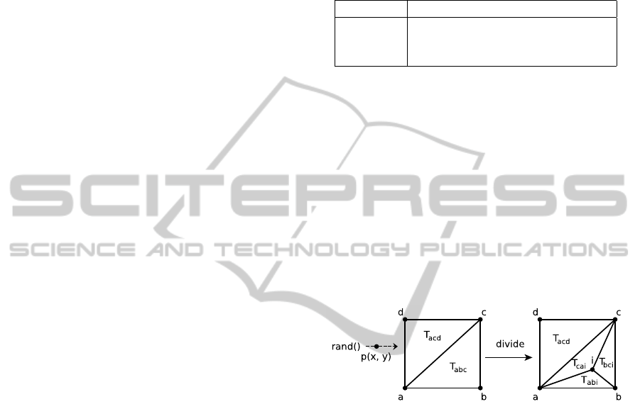
5.1 2D Triangulations
The set of tests consists of fully random bad-quality
triangulations in the sense that they need a high num-
ber of edge flips to be transformed into Delaunay tri-
angulations. These inputs are generated by placing
random points inside two adjacent triangles starting
from a square domain. For each new inserted point,
the triangle that includes the point is divided into three
smaller triangles as shown in Figure 7. The size of the
test triangulations ranges from 100 thousand to 5 mil-
lion points and the smallest angle of all the meshes is
practically zero (less than 10
−6
radians).
Figure 7: Construction of a full random mesh.
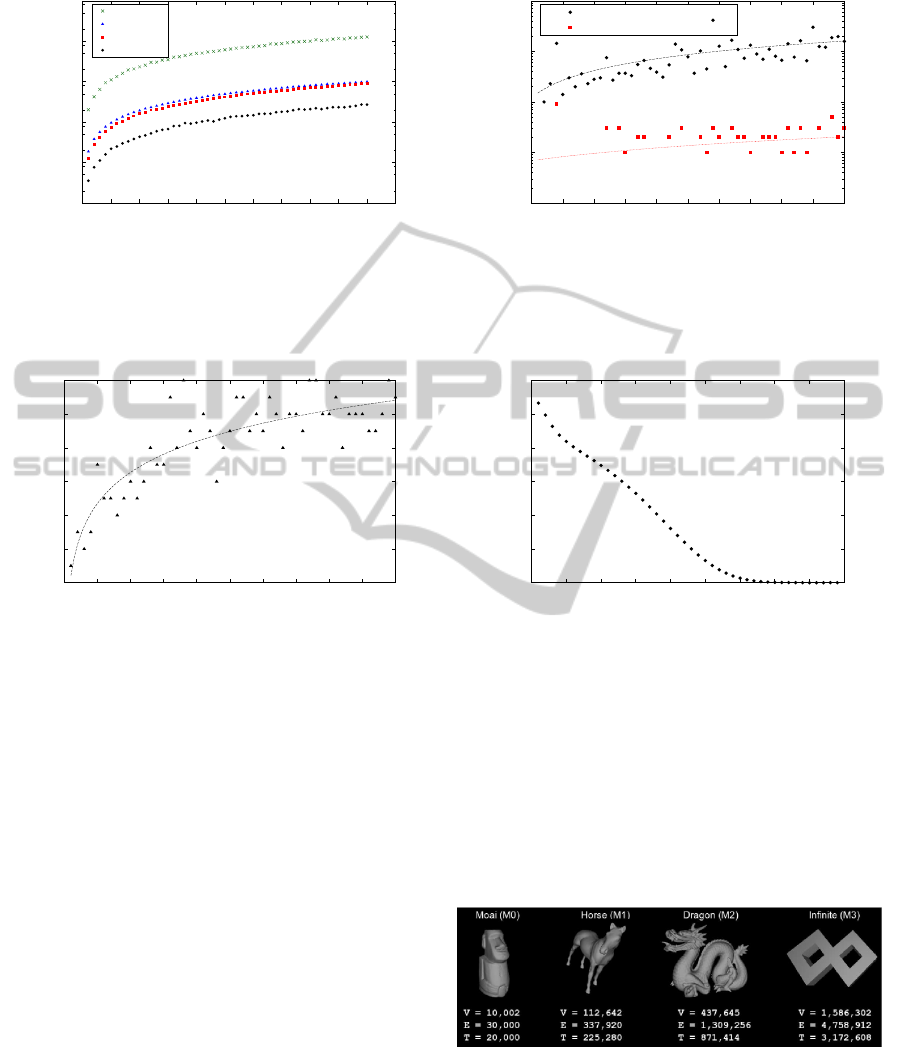
In Figure 8(a) we present the computational time
for each mesh size. It can be observed that MDT is
approximately three times faster in these bad quality
triangulations than the algorithms inside the CGAL
library and the Triangle software. There is also a
speedup of 50× with respect to our sequential im-
plementation of Lawson’s original edge-flip method.
In Figure 8(b) we show the quality of the generated
meshes in the sense of how close they are to being full
Delaunay meshes. We took the meshes generated by
the CGAL library as reference triangulations. Both
MDT and Triangle generate different triangles with
respect to the reference triangulations. However, the
missed triangles, i.e, the triangles that are in the trian-
gulations generated by MDT and Triangle, and are not
in the reference triangulations, are less than 0.05%.
The error rate is computed as the number of missed
triangles with respect to the total number of triangles
of the reference triangulation. Note that the triangu-
lations generated by CGAL and Triangle are different
because Triangle modifies the vertex list if two points
AGPU-basedMethodforGeneratingquasi-DelaunayTriangulationsbasedonEdge-flips
31
0.01
0.1
1
10
100
1000
0 0.5 1 1.5 2 2.5 3 3.5 4 4.5 5 5.5
time [s]
# vertices (10^6)
CPU-Construction vs GPU-Transformation
Lawson
CGAL
Triangle
MDT
1e-05
1e-04
1e-03
1e-02
1e-01
0 0.5 1 1.5 2 2.5 3 3.5 4 4.5 5
% error
# vertices (10^6)
% of error
MDT / CGAL
Triangle / CGAL
(a) (b)
Figure 8: (a) Computational time for all methods and (b) Differences of Triangle and MDT triangulations with respect to
CGAL triangulation.
34
36
38
40
42
44
46
0 0.5 1 1.5 2 2.5 3 3.5 4 4.5 5
# iterations
# vertices (10^6)
GPU iterations
0e+00
5e+05
1e+06
2e+06
2e+06
2e+06
3e+06
0 5 10 15 20 25 30 35 40 45
# edge flips
# iteration
Edge flips per iteration for input n=5M
(a) (b)
Figure 9: (a) Number of iterations vs. problem size, (b) number of edge-flips vs. iterations for the biggest input case (a mesh
of 5 million points).
are too close to each other. Some important aspects of
the behavior of the MDT are shown in Figure 9. Fig-
ure 9(a) shows an approximated curve that represents
the number of iterations versus the mesh size. Empiri-
cally, this curve shows a complexity of O(log n). Fig-
ure 9(b) shows how the number of edge flips changes
among the iterations while transforming the triangu-
lation of 5 million vertices and approximately 15 mil-
lion edges. We can observe that during the first half of
the iterations, most of the edge-flips are done, while
in the last iterations few edge flips are executed. For
this input, both MDT and Lawson’s edge-flip methods
performed approximately 37 million edge-flips. It is
worth mentioning that in all the tested triangulations,
the percentage of edge flips done in parallel was more
than 80% (i.e., the excluded threads were less than
20%).
5.2 3D Surface Triangulations
MDT was originally intended for improving the min-
imum angle of smooth 3D surface triangulations for
the modeling of tree stem deformations. An edge e
is considered for flipping only if the normal vectors
of the two neighbor triangles that share e are almost
parallel according to some threshold value. Figure 10
shows the different test inputs with their correspond-
ing number of vertices, edges and triangles.
Figure 10: 3D Surface test-case meshes.
The dragon was taken from the Stanford Com-
puter Graphics Laboratory, the horse from Cyberware
Inc, the Moai from the GeomView examples and the
Infinite was built with our custom tools. Figure 11
shows the performance of the MDT and our imple-
GRAPP2013-InternationalConferenceonComputerGraphicsTheoryandApplications
32

mentation of the Lawson sequential algorithm. (The
traced lines were added to connect the measurements
using the same implementation.) As expected, the
MDT method achieves a speedup of 80× . Table 2
shows the number of flipped-edges and the percent-
age of excluded threads for each iteration in the four
input meshes. As in the 2D tests, the first iterations
do most of the required edge-flips. The number of
iterations is lower than in the 2D tests because these
surface triangulations have an overall better quality.
0.0001
0.001
0.01
0.1
1
10
Moai Dragon Horse Infinite
time [s]
mesh
3D surface improvement times
MDT
Lawson CPU
Figure 11: Performance results on 3D meshes.
6 RELATED WORK
There is a considerable amount of work on the subject
of computing Delaunay triangulations, from sequen-
tial implementations (Paul Chew, 1989; Shewchuk,
1996; De Berg, 2000) to parallel ones (Antonopou-
los et al., 2005; Healey et al., 1997; Kohout and
Kolingerov´a, 2003; Rong et al., 2008). Most of these
works belong to the case when a Delaunay triangu-
lation needs to be computed from a set of points or
from a PSLG, and not from an existing triangulation.
To the best of our knowledge, only recently has the
edge-flip technique been used in the design of parallel
GPU-based algorithms for the generation of triangu-
lations. Cao Thang (Cao, 2010) developed an algo-
rithm for the generation of a Delaunay triangulation
and its Voronoi diagram from a set of points. One step
of his method performs GPU-based edge-flips; the al-
gorithm maps threads to triangles. Cervenansk´y et al.
(Cervenansk´y et al., 2010) propose a GPU-based tri-
angulation algorithm for image processing. Edges are
flipped in parallel, as we also do, but by using a differ-
ent approachfor deciding which subset of them can be
flipped in parallel (i.e., they do not use Delaunay con-
ditions). Harada (Harada, 2011) proposed a constraint
solver for rigid body simulation. In his work, threads
are assigned to pairs of adjacent triangles by using
atomic operations in the same way as we do for decid-
ing which non-Delaunay edges can be flipped in par-
allel. Unfortunately,we could not compare our imple-
mentation directly with the parallel edge-flip methods
of the authors because different hardware was used
in their results and they only compare their edge-flip
routine against prior work of themselves. We think it
is a better practice to use the standard method of com-
parison in parallel computing; to measure speedups
against a reference sequential algorithm.
7 DISCUSSION
AND CONCLUSIONS
We have presented a GPU-based implementation for
computing quasi-Delaunay triangulations. The so-
lution is compatible with OpenGL, handles special
cases such as co-circular point configurations and is
free of dead-locks. The behavior of the MDT shows
several interesting aspects. The amount of edge-flips
per iteration quickly decreases, making the first half
of the iterations much more important than the rest.
We report an exclusion rate of threads under 20%
serving as a guarantee that parallelism can indeed be
useful. The curve of the number of iterations as a
function of the mesh size empirically shows a com-
plexity of O(log n). This is a good behavior since
GPU methods are aimed at addressing large problems
and less iterations means more parallelism. The worst
behavior of the algorithm is when edge-flips can not
be done in parallel. In this case the computational
complexity for the sequential and parallel algorithms
is the same.
We analyzed the performance of MDT under dif-
ferent inputs; bad-quality random 2D triangulations
and popular 3D surface meshes. Our experimental
evaluation shows that the percentage of missed tri-
angles of the triangulations generated by MDT with
respect to the triangulations generated by CGAL was
less than 0.05% in all experiments. On these bad qual-
ity meshes, MDT obtains a speedup of up to 50× with
respect to Lawson’s O(n
2
) edge-flip method on CPU
and a speedup of 3× with respect to the 2D O(nlog n)
algorithms available inside CGAL and Triangle. This
speedup seems to be not so impressive as we are com-
paring GPU with CPU implementations and quasi-
Delaunay triangulations with exact ones. However, it
is important to mention that the MDT implementation
is sensitive to the topology of the input triangulation
and the CGAL and Triangle implementations are not
because they are constructive methods. This means
that if the input mesh needs little work to become De-
launay, the speedup of MDT with respect to CGAL
and Triangle should be higher than 3×.
AGPU-basedMethodforGeneratingquasi-DelaunayTriangulationsbasedonEdge-flips
33
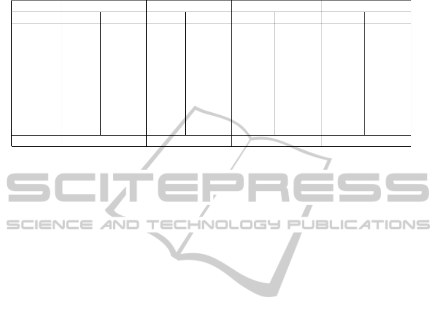
Table 2: Detail of effective edge-flips and parallelism ratio at each iteration for the 3d examples.
Moai Horse Dragon Infinite
#iteration flipped excluded flipped excluded flipped excluded flipped excluded
1 1,786 3.88% 31,453 0.08% 106,101 6.63% 508,502 8.62%
2 215 1.83% 4,376 0.21% 22,608 4.08% 237,340 8.48%
3 41 4.66% 598 1.65% 4,455 5.86% 95,975 3.81%
4 3 0% 131 4.38% 995 1.49% 29,568 5.95%
5 1 0% 33 8.34% 207 1.43% 7,882 4.52%
6 10 0% 34 0% 2,844 1.6%
7 4 0% 1 0% 762 5.81%
8 1 0% 195 6.25%
9 40 0%
10 11 0%
Total flips 2,046 36,596 134,401 883,119
Our proposed implementation is useful for appli-
cations that need to quickly improvethe minimum an-
gle of triangulations and visualize a mesh at the same
time; dynamic terrain manipulation and tree stem de-
formations to name some examples. In the near fu-
ture, we will compare the in-circle test with the oppo-
site angle test used in this implementation. We also
want to test the algorithm with bad quality 3D surface
meshes.
ACKNOWLEDGEMENTS
This work was partially supported by Fondecyt
Project N
o
1120495.
REFERENCES
Antonopoulos, C. D., Ding, X., Chernikov, A., Blagojevic,
F., Nikolopoulos, D. S., and Chrisochoides, N. (2005).
Multigrain parallel Delaunay mesh generation: chal-
lenges and opportunities for multithreaded architec-
tures. In Proceedings of the 19th annual international
conference on Supercomputing, ICS ’05, pages 367–
376, New York, NY, USA. ACM.
Cao, T. T. (2010). Computing 2d Delaunay triangulation
using GPU. Manuscript in preparation.
Cervenansk´y, M., T´oth, Z., Starinsk´y, J., Ferko, A.,
and Sr´amek, M. (2010). Parallel GPU-based data-
dependent triangulations. Computers & Graphics,
34(2):125–135.
De Berg, M. (2000). Computational Geometry: Algo-
rithms and Applications. Springer-Verlag TELOS,
Santa Clara, CA, USA.
Edelsbrunner, H. (2001). Geometry and topology for mesh
generation (Cambridge monographs on applied and
computational mathematics).
Fortune, S. (1993). A note on Delaunay diagonal flips”.
Pattern Recognition Letters, 14(9):723 – 726.
Harada, T. (2011). A parallel constraint solver for a rigid
body simulation. In SIGGRAPH Asia 2011 Sketches,
SA ’11, pages 22:1–22:2, New York, NY, USA. ACM.
Healey, R. G., Minetar, M. J., and Dowers, S., editors
(1997). Parallel Processing Algorithms for GIS. Tay-
lor & Francis, Inc., Bristol, PA, USA.
Kohout, J. and Kolingerov´a, I. (2003). Parallel Delau-
nay triangulation based on circum-circle criterion. In
SCCG ’03: Proceedings of the 19th spring conference
on Computer graphics, pages 73–81, New York, NY,
USA. ACM.
Lawson, C. L. (1972). Transforming triangulations. Dis-
crete Mathematics, 3(4):365 – 372.
Navarro, C., Hitschfeld-Kahler, N., and Scheihing, E.
(2011). A parallel GPU-based algorithm for Delaunay
edge-flips. In Abstracts from 27th European Workshop
on Computational Geometry (EUROCG2011), pages
75–78. Morschach, Switzerland.
Nvidia (2011). NVIDIA CUDA Compute Unified Device
Architecture - Programming Guide.
Paul Chew, L. (1989). Constrained Delaunay triangulations.
Algorithmica, 4:97–108.
Rong, G., Tan, T.-S., Cao, T.-T., and Stephanus (2008).
Computing two-dimensional Delaunay triangulation
using graphics hardware. In I3D ’08: Proceedings of
the 2008 symposium on Interactive 3D graphics and
games, pages 89–97, New York, NY, USA. ACM.
Shewchuk, J. R. (1996). Triangle: Engineering a 2d quality
mesh generator and Delaunay triangulator. In ACM,
editor, First Workshop on Applied Computational Ge-
ometry, pages 124–133. (Philadelphia, Pennsylvania).
CGAL (2012). CGAL, Computational Geometry Algo-
rithms Library. http://www.cgal.org.
Tobler, R. F. and Maierhofer, S. (2006). A mesh data struc-
ture for rendering and subdivision. In WSCG ’2006:
Proceedings of WSCG (International Conference in
Central Europe on Computer Graphics, Visualization
and Computer Vision), pages 157–162.
GRAPP2013-InternationalConferenceonComputerGraphicsTheoryandApplications
34
