
Depth-Assisted Rectification of Patches
Using RGB-D Consumer Devices to Improve Real-time Keypoint Matching
João Paulo Lima
1
, Francisco Simões
1
, Hideaki Uchiyama
2
, Veronica Teichrieb
1
and Eric Marchand
2
1
Voxar Labs, Informatics Center, Federal University of Pernambuco, Av. Jorn. Anibal Fernandes, S/N, Recife, Brazil
2
INRIA Rennes Bretagne-Atlantique, Rennes, France
Keywords: Keypoint Matching, Pose Estimation, Computer Vision, RGB-D.
Abstract: This paper presents a method named Depth-Assisted Rectification of Patches (DARP), which exploits depth
information available in RGB-D consumer devices to improve keypoint matching of perspectively distorted
images. This is achieved by generating a projective rectification of a patch around the keypoint, which is
normalized with respect to perspective distortions and scale. The DARP method runs in real-time and can be
used with any local feature detector and descriptor. Evaluations with planar and non-planar scenes show that
DARP can obtain better results than existing keypoint matching approaches in oblique poses.
1 INTRODUCTION
This paper introduces a novel technique for object
detection and tracking named Depth-Assisted
Rectification of Patches (DARP). The proposed
technique can provide rotation, scale and perspective
invariant features based on a patch rectification
approach. The DARP method is designed to make
use of RGB-D sensors, such as consumer devices
like Microsoft Kinect, and exploit both image and
depth data to improve feature detection and
description. RGB-D sensors became in the last years
a low cost consumer product of easy access to
general users. The DARP technique uses the depth
data provided by such sensors to estimate normals
on the scene surface of 3D points that correspond to
keypoints extracted from the RGB image. The depth
data is also used together with the estimated normals
to rectify patches around the keypoints with fixed
size in camera coordinates. This contributes to
remove perspective distortions caused by oblique
poses and scale changes, and it shall be
demonstrated that using the descriptors computed
from the rectified patches for real-time keypoint
matching can give improved results.
Since perspective deformations can be
approximated by affine transformations for small
areas, affine invariant local features can be used to
generate normalized patches (Mikolajczyk et al.,
2005). On the other hand, DARP can use local
features that are, a priori, not affine and scale
invariant, performing a posteriori projective
rectification of the patches. The ASIFT method
(Morel and Yu, 2009) obtains a higher number of
matches from perspectively distorted images by
generating several affine transformed versions of
both images and then finding correspondences
between them using SIFT. Alternatively, the DARP
method is able to use solely the query and template
images in order to match them. ASIFT also makes
use of low-resolution versions of the affine
transformed images in order to accelerate keypoint
matching. Only the affine transforms that provide
more matches are used to compare the images in
their original resolution. The DARP technique is
able to work directly with high resolution images,
without needing to decrease their quality to achieve
real-time keypoint matching. In (Koser and Koch,
2007), MSER features are projectively rectified
using Principal Component Analysis (PCA) and
graphics hardware. However, it does not focus on
real-time execution and it is designed to work with
region detectors, while the DARP method works
with keypoint detectors and computes rectified
patches in real-time. Patch perspective rectification
is also performed in (Del Bimbo et al., 2010),
(Hinterstoisser et al., 2008), (Hinterstoisser et al.,
2009) and (Pagani and Stricker, 2009). These
methods differ from DARP because they first
estimate patch identity and coarse pose, and then
refine the pose of the identified patch. In DARP, the
651
Lima J., Simões F., Uchiyama H., Teichrieb V. and Marchand E..
Depth-Assisted Rectification of Patches - Using RGB-D Consumer Devices to Improve Real-time Keypoint Matching.
DOI: 10.5220/0004284406510656
In Proceedings of the International Conference on Computer Vision Theory and Applications (VISAPP-2013), pages 651-656
ISBN: 978-989-8565-47-1
Copyright
c
2013 SCITEPRESS (Science and Technology Publications, Lda.)

patches are first rectified in order to allow estimating
their identity. In addition, these methods need to
previously generate warped versions of the patch for
being able to compute its rectification, while DARP
can rectify a patch without such constraint. The
methods described in (Eyjolfsdottir and Turk, 2011),
(Kurz and Benhimane, 2011), (Wu et al., 2008) and
(Yang et al., 2010) first projectively rectify the
whole image and then detect invariant features on
the normalized result, while the DARP method does
the opposite. In addition, (Wu et al., 2008) is
designed for offline 3D reconstruction, (Eyjolfsdottir
and Turk, 2011), (Kurz and Benhimane, 2011) and
(Yang et al., 2010) target only planar scenes and
(Eyjolfsdottir and Turk, 2011) and (Kurz and
Benhimane, 2011) require an inertial sensor.
Concurrent with this research (Marcon et al., 2012)
used an RGB-D sensor to perform patch rectification
using PCA, followed by 2D Fourier-Mellin
Transform for description. Nevertheless, the
rectification algorithm applied is not clearly
described, it is not evaluated under a real-time
keypoint matching scenario and only planar scenes
are used in the experiments.
The contributions of this paper are: (1) patch
rectification method that uses depth information to
obtain a perspective and scale invariant
representation of keypoints; (2) qualitative and
quantitative evaluation of the technique, showing
that it is suitable to both planar and non-planar
scenes and provides good results in oblique poses;
(3) runtime analysis of the method, which shows that
it runs in real-time.
This paper is organized as follows. Section 2
describes each step of the DARP technique. Section
3 discusses the results obtained with DARP and
presents qualitative and quantitative evaluations with
respect to keypoint matching quality and runtime
performance. Conclusions and future work are
detailed in Section 4.
2 DEPTH-ASSISTED
RECTIFICATION OF PATCHES
In DARP, keypoints are extracted and their normal
vectors on the scene surface are estimated using the
depth image. Then, using depth and normal
information, patches around the keypoints are
rectified to a canonical view in order to remove
perspective and scale distortions. For rotation
invariance, the rectified patch orientation is
computed using geometric moments. A descriptor
for the rectified patch is computed using the
assigned orientation. The query descriptors are
matched with previously obtained template
descriptors. Camera pose can then be estimated from
the correspondences. Each step of the DARP method
is detailed on the next subsections.
2.1 Keypoint Detection
Any keypoint detector can be used by DARP. Since
the patch around the keypoint is normalized a
posteriori with respect to perspective distortions and
scale, the detector does not have to be affine or scale
invariant and the use of a scale pyramid for the input
image is not mandatory. In the current
implementation, the DARP method uses FAST-9
(Rosten and Drummond, 2006), since it presents a
good tradeoff between efficiency and quality. The
keypoints are detected using the original scale of the
input image, without employing a scale pyramid. An
initial set of features is detected on the input image
and then points with best Harris response are
selected. It was used a value of 230 in the
conducted experiments.
2.2 Normal Estimation
From the query depth image, a 3D point cloud in
camera coordinates can be computed for the scene.
Considering a 3D point
,
,
in
camera coordinates, its 2D projection
,
,
1
is given by:
⁄
⁄
1
0
0
001
⁄
⁄
1
,
(1)
where
and
are the focal length in terms of pixel
dimensions in the and direction respectively,
and
are the coordinates of the principal point and
is known as the intrinsic parameters matrix. Thus,
rearranging the terms and considering
,
where is the depth of , the coordinates of
can be obtained by:
∙
⁄
∙
⁄
.
(2)
Using this point cloud, a normal vector can be
estimated for a 3D point
that corresponds to
VISAPP2013-InternationalConferenceonComputerVisionTheoryandApplications
652

an extracted 2D keypoint via PCA. The centroid
of all neighbour 3D points
within a radius of
3 cm of
is computed. A covariance matrix is
computed using
and
, and its eigenvectors
,
,
and corresponding eigenvalues
,
,
are computed and ordered in ascending
order. The normal vector to the scene surface at
is given by
(Berkmann and Caelli, 1994).
If needed,
is flipped to point towards the viewing
direction. Only the keypoints that have a valid
normal are kept.
2.3 Patch Rectification
The next step consists in using the available 3D
information to rectify a patch around each keypoint
in order to remove perspective deformations. In
addition, a scale normalized representation of the
patch is obtained. This is done by computing a
homography that transfers the patch to a canonical
view, as illustrated in Figure 1. Given
,
,
as the unit normal vector in camera
coordinates at
, which is the corresponding 3D
point of a keypoint, two unit vectors
and
that
define a plane with normal can be obtained by:
,,
∙
,0,
,
(3)
.
(4)
This is valid because it is assumed that
and
are
not equal to zero at the same time, since in this case
the normal would be perpendicular to the viewing
direction and the patch would be not visible.
From
,
and
, it is possible to find the
3D corners
, …,
of the patch in the camera
coordinate system. The patch size in camera
coordinates should be fixed in order to allow scale
invariance. The 2D corners
, …,
of the patch
to be rectified in image coordinates are the
projection of the 3D points
, …,
, i.e.,
. If the patch size in image coordinates is
too small, the rectified patch will suffer degradation
in image resolution, harming its description. This
size is influenced by the location of the 3D point
(e.g., if
is too far from the camera, the
patch size will be small). It is also directly
proportional to the patch size in camera coordinates,
which is determined by a constant factor applied
to
and
as follows:
′∙
and
′∙
. The factor should be large enough to allow
good scale invariance while being small enough to
give distinctiveness to the patch. In the performed
experiments, it was used /2, where is the
size of the rectified patch (set to 31 in the tests).
Figure 1: Patch rectification overview.
, …,
are
computed from
,
′ and
′. An homography is
computed from the projections
, …,
and the
canonical corners
′, …,
′.
The corners
, …,
of the patch are given by:
′
′,
(5)
′
′,
(6)
′
′,
(7)
′
′.
(8)
The corresponding corners
′, …,
′ of the patch
in the canonical view are:
′1,0
,
(9)
′1,1
,
(10)
′0,1
,
(11)
′0,0
.
(12)
From
, …,
and
′, …,
′, it can be
computed an homography that takes points of the
input image to points of the rectified patch.
2.4 Orientation Estimation
In order to achieve rotational invariance, patch
orientation can be estimated based on the intensity
centroid, which is computed from geometric
moments (Rublee et al., 2011). Compared to
gradient-based methods, the use of intensity centroid
has the advantage of presenting a uniformly good
orientation even under large image noise (Rublee et
al., 2011), besides being fast to compute.
2.5 Patch Description
The same way DARP can use any keypoint detector,
it is also possible to have any patch descriptor. In the
current implementation, the Rotation-Aware BRIEF
(rBRIEF) was used due to its good performance and
simple rotational invariance treatment (Rublee et al.,
2011). The rBRIEF descriptor is based on binary
tests over a smoothed patch, but with steered
versions of the tests. Each steered pattern
Depth-AssistedRectificationofPatches-UsingRGB-DConsumerDevicestoImproveReal-timeKeypointMatching
653
corresponds to a discretized rotation angle applied to
the coordinates of the binary tests. A lookup table of
the steered patterns is created to speed up the
matching process. In addition, a learning approach is
used in order to obtain a good set of binary tests. At
runtime, the steered version to be used for
generating the descriptor is chosen based on the
assigned orientation of the patch. DARP used 30
distinct angles for the discretization.
2.6 Descriptor Matching and Pose
Estimation
For descriptor matching, a nearest neighbour search
is performed in order to find the corresponding
template descriptor for each query descriptor. In the
tests performed, a brute force search with Hamming
distance was applied, where matches with a distance
greater than 50 are discarded.
Regarding pose estimation, if the objects present
on the scene are planar, homography estimation can
be used to compute their pose. If the scene is non-
planar, a Perspective––Point (PP) method can be
applied. In the experiments performed, planar
objects pose were computed using homography
estimation with the DLT method, while non-planar
objects pose were estimated using the EPP method
(Moreno-Noguer et al., 2007). In both cases, the
RANSAC algorithm was applied for outliers
removal.
3 RESULTS
In order to evaluate DARP, some image sequences
from the publicly available University of
Washington’s RGB-D Object Dataset (Lai et al.,
2011) were used and synthetic RGB-D images were
also generated. All the experiments were performed
with 640x480 images. The hardware used in the
evaluation was a Microsoft Kinect for Xbox 360 and
a laptop with Intel Core i7-3612QM @ 2.10GHz
processor and 8GB RAM.
The results obtained with DARP were compared
with ORB (Rublee et al., 2011), since the current
implementation of DARP performs keypoint
detection, orientation assignment and patch
description in a way similar to ORB. It should be
noted that ORB uses an image pyramid with 5 levels
and a scale factor of 1.2 in order to obtain scale
invariance, while DARP does not make use of an
image pyramid, since scale changes are inherently
handled using the patch rectification process. ORB
extracts 631 keypoints per image pyramid,
distributed in the levels in ascending order as
follows: 230, 160, 111, 77 and 53 keypoints. The
DARP technique uses only the 230keypoints
extracted from the first level. Two images of the
same object with different poses were matched using
both techniques. Descriptor matching and pose
estimation were performed using the same
procedures for both DARP and ORB, as described in
Subsection 2.6.
3.1 Qualitative Evaluation
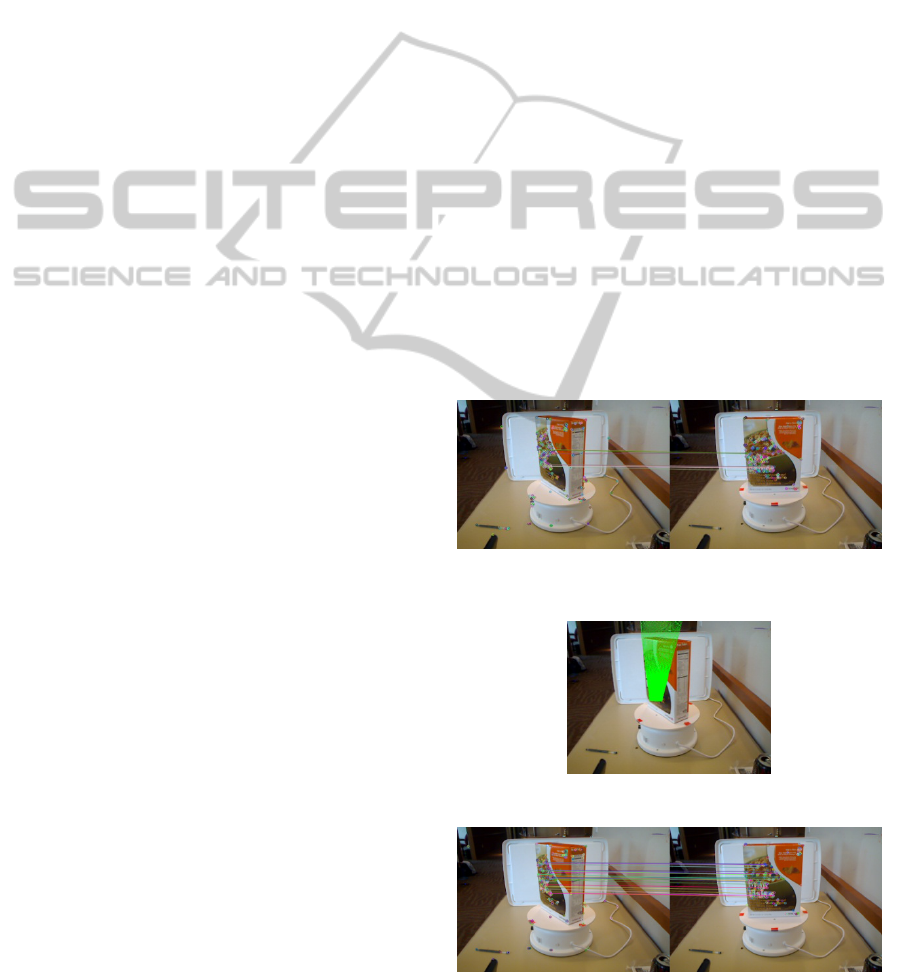
Initially the tests were done with planar objects. It is
shown in Figure 2 and Figure 4 the matches between
the two instances of a planar object in the frames
cereal_box_1_1_176 and cereal_box_1_1_208 from
the University of Washington’s RGB-D Object
Dataset. The 2D points that belong to the object
model transformed by the homographies computed
from the matches are shown in Figure 3 and Figure
5
. It can be noted that the DARP method provides
better results than ORB when the object has an
oblique pose with respect to the viewing direction.
The matches obtained with ORB led to a wrong
pose, while it was possible to estimate a reasonable
pose using DARP, as evidenced by the transformed
model points.
Figure 2: Planar object keypoint matching using ORB
finds 10 matches.
Figure 3: Planar object pose estimation using ORB.
Figure 4: Planar object keypoint matching using DARP
finds 27 matches.
VISAPP2013-InternationalConferenceonComputerVisionTheoryandApplications
654
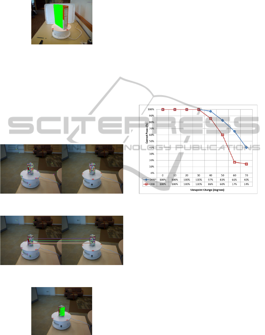
Figure 5: Planar object pose estimation using DARP.
After, some tests were done with non-planar objects.
In this case, Figure 8 illustrates the projection of a
3D point cloud model of the object using the pose
computed from the matches found by DARP shown
in Figure 7. The frames from the University of
Washington’s RGB-D Object Dataset used in this
experiment are food_can_14_1_181 and
food_can_14_1_197. DARP also obtained better
results than ORB in the oblique pose scenario, since
DARP provided matches that allowed computing the
object pose, while ORB did not find any valid
matches, as can be seen in Figure 6.
Figure 6: Non-planar object keypoint matching using ORB
finds 0 matches.
Figure 7: Non-planar object keypoint matching using
DARP finds 14 matches.
Figure 8: Non-planar object pose estimation using DARP.
3.2 Quantitative Evaluation
Keypoint matching quality was evaluated by
measuring the correctness of the poses estimated
from the matches with a database of 280 synthetic
RGB-D images of a planar object (a cereal box)
under different viewpoints on a cluttered
background. The poses were under a degree change
range of 0°,70° with a 10° step and a scale range
of 1.0,2.0 with a 0.2 step. The percentage of
correct poses estimated by each method was
calculated. The pose was considered as correct only
if the root-mean-square (RMS) reprojection error
was below 3 pixels. Figure 9 shows that DARP
outperformed ORB in larger viewpoint changes.
Figure 9: Percentage of correct poses of ORB and DARP
with respect to viewpoint change.
3.3 Performance Analysis
Table 1 presents the average time and the percentage
of time required by each step of ORB and a non-
optimized implementation of the DARP method. It
shows that the DARP method runs at ~36 fps and its
most time demanding step is the normal estimation
phase, which takes more than 50% of all processing
time. The patch rectification step also heavily
contributes to the final processing time. ORB takes
more time than DARP for keypoint detection and
patch description, since it uses an image pyramid
and extracts a higher number of keypoints. ORB
estimates patch orientation in a faster manner than
DARP because it makes use of integral images in
this step. DARP could be optimized to perform
orientation estimation in the same way, but it would
not represent a significant performance gain, as this
step takes less than 1% of total processing time.
Depth-AssistedRectificationofPatches-UsingRGB-DConsumerDevicestoImproveReal-timeKeypointMatching
655

Table 1: Average computation time and percentage for
each step of ORB and DARP methods.
ORB DARP
ms % ms %
Keypoint detection 16.11 80.89 2.63 9.40
Normal estimation – – 14.99 53.56
Patch rectification – – 8.40 30.01
Orientation estimation 0.14 0.71 0.20 0.72
Patch description 3.67 18.40 1.77 6.31
Total 19.92 100.00 27.99 100.00
4 CONCLUSIONS
The DARP method has been introduced, which
exploits depth information to improve keypoint
matching. This is done by rectifying the patches
using the 3D information in order to remove
perspective distortions. The depth information is
also used to obtain a scale invariant representation of
the patches. It was shown that DARP can be used
together with existing keypoint matching methods in
order to help them to handle situations such as
oblique poses with respect to the viewing direction.
It supports both planar and non-planar objects and is
able to run in real-time.
As future work, tests with other keypoint
detectors and patch descriptors will be done.
Optimizations on normal estimation and patch
rectification are also planned, since they showed to
be the most time demanding steps of the technique.
REFERENCES
Berkmann, J., Caelli, T., 1994. Computation of surface
geometry and segmentation using covariance
techniques. In IEEE Transactions on Pattern Analysis
and Machine Intelligence, volume 16, issue 11, pages
1114–1116.
Del Bimbo, A., Franco, F., Pernici, F., 2010. Local
homography estimation using keypoint descriptors. In
WIAMIS’10, 11th International Workshop on Image
Analysis for Multimedia Interactive Services, 4 pages.
Eyjolfsdottir, E., Turk., M., 2011. Multisensory embedded
pose estimation. In WACV’11, IEEE Workshop on
Applications of Computer Vision, pages 23–30.
Hinterstoisser, S., Benhimane, S., Navab, N., Fua, P.,
Lepetit, V., 2008. Online learning of patch perspective
rectification for efficient object detection. In
CVPR’08, 21th IEEE Conference on Computer Vision
and Pattern Recognition, 8 pages.
Hinterstoisser, S., Kutter, O., Navab, N., Fua, P., Lepetit,
V., 2009. Real-time learning of accurate patch
rectification. In CVPR’09, 22th IEEE Conference on
Computer Vision and Pattern Recognition, pages
2945–2952.
Koser, K., Koch, R., 2007. Perspectively invariant normal
features. In ICCV’07, 11th IEEE International
Conference on Computer Vision, 8 pages.
Kurz, D., Benhimane, S., 2011. Gravity-aware handheld
augmented reality. In ISMAR’11, 10th IEEE
International Symposium on Mixed and Augmented
Reality, pages 111–120.
Lai, K., Bo, L., Ren, X., Fox, D., 2011. A large-scale
hierarchical multi-view RGB-D object dataset. In
ICRA’11, IEEE International Conference on Robotics
and Automation, pages 1817–1824.
Marcon, M., Frigerio, E., Sarti, A., Tubaro, S., 2012. 3D
wide baseline correspondences using depth-maps. In
Signal Processing: Image Communication, volume 27,
issue 8, pages 849–855.
Mikolajczyk, K., Tuytelaars, T., Schmid, C., Zisserman,
A., Matas, J., Schaffalitzky, F., Kadir, T., Van Gool,
L., 2005. A comparison of affine region detectors. In
International Journal of Computer Vision, volume 5,
issue 1–2, pages 43–72.
Morel, J., Yu, G., 2009. ASIFT: A new framework for
fully affine invariant image comparison. In SIAM
Journal on Imaging Sciences, volume 2, issue 2, pages
438–469.
Moreno-Noguer, F., Lepetit, V., Fua, P., 2007. Accurate
non-iterative O(n) solution to the PnP problem. In
ICCV’07, 11th IEEE International Conference on
Computer Vision, 8 pages.
Pagani, A., Stricker, D., 2009. Learning local patch
orientation with a cascade of sparse regressors. In
BMVC’09, 20th British Machine Vision Conference,
pages 86.1–86.11.
Rosten, E., Drummond, T., 2006. Machine learning for
high-speed corner detection. In ECCV’06, 9th
European Conference on Computer Vision, pages
430–443.
Rublee, E., Rabaud, V., Konolige, K., Bradski, G., 2011.
ORB: an efficient alternative to SIFT or SURF. In
ICCV’11, 15th IEEE International Conference on
Computer Vision, pages 2564–2571.
Wu, C., Clipp, B., Li, X., Frahm, J.-M., Pollefeys, M.,
2008. 3D model matching with viewpoint invariant
patches (VIPs). In CVPR’08, IEEE Conference on
Computer Vision and Pattern Recognition, 8 pages.
Yang, M., Cao, Y., Förstner, W., McDonald, J., 2010.
Robust wide baseline scene alignment based on 3d
viewpoint normalization. In ISVC’10, 6th
International Symposium on Visual Computing,
Lecture Notes in Computer Science, volume 6453,
pages 654–665.
VISAPP2013-InternationalConferenceonComputerVisionTheoryandApplications
656
