
3D Representation Models Construction through a Volume Geometric
Decomposition Method
Gisele Simas, Rodrigo de Bem and Silvia Botelho
Centro de Ci
ˆ
encias Computacionais (C3), Universidade Federal do Rio Grande (FURG),
Av. It
´
alia, km 8, 96203-900, Rio Grande, RS, Brazil
Keywords:
Representation Model, Volumetric Reconstruction, 3D Motion Tracking.
Abstract:
Despite the fact of 3D motion tracking has being highly explored in the computer vision researches, it still faces
some relevant challenges, such as the tracking of objects using few a priori knowledge. In this context, this
work presents the Volume Geometric Decomposition method, capable of constructing representation models
of distinct and previously unknown objects. This method is executed over a probabilistic volumetric recon-
struction of the interested objects. It adjusts the representation to the reconstructed volume, minimizing the
amount of empty space enclosed by the model. Such representation model is composed by an appearance and
a kinematic models. The former is comprised of ellipsoids and joints, while the latter is implemented through
the Loose-Limbed model, a probabilistic graphical model. The performed experiments and the obtained results
shown that the proposed method successfully constructed representation models to highly distinct and a priori
unknown objects.
1 INTRODUCTION
The 3D motion tracking has being highly explored in
the computer vision researches. Realistic results are
already achieved specifically in human motion track-
ing (Sigal and Black, 2010). However, the tracking
methods still have certain limitations. In order to
reduce these restrictions, in recent years, greater at-
tention has being devoted to obtaining more general
methods that allow: motion tracking from monocu-
lar images (Fossati et al., 2009); use of unsynchro-
nized moving cameras (Hasler et al., 2009); the ex-
emption from manual initialization (Sundaresan and
Chellappa, 2009); adaptation to different forms of the
same object (Miki
´
c et al., 2003); online processing
of modifications (Ross et al., 2008); motion tracking
of distinct objects (Ukita et al., 2009); reduction of
the needed amount of a priori information (Gall et al.,
2010).
The overcome of some restrictions passes through
the use of more general and flexible representation
models. In the context of motion tracking frame-
works, the representation models are employed to
model the tracking objects, gathering relevant infor-
mation about their structure and appearance. Accord-
ing to Caillette (Caillette, 2006), the representation
models can be classified as: i) appearance models:
describe properties of the objects’ parts, such as shape
and color; ii) kinematic models: describe the kine-
matical relations between the objects’ parts, estab-
lishing spacial relations and movement rules through
them; iii) dynamic models: describe the mechani-
cal properties of the objects’ parts, considering their
masses, sizes and forces.
Representation models are employed in many ap-
plications, such as animation (Starck and Hilton,
2007), motion capture (Gall et al., 2010), segmen-
tation (Mian et al., 2006), object recognition (To-
shev et al., 2009) and motion synthesis (Huang et al.,
2009). This is possible because model based ap-
proaches allow the representation of distinct objects,
the gathering of visual, structural and mechanical ob-
jects’ properties, and the representation of distinct
poses of objects.
Thus, this work proposes a novel approach for au-
tomatic representation model construction of distinct
and a priori unknown objects. This method is part of a
markerless 3D motion tracking framework, based on
probabilistic volumetric reconstruction, which has the
goal of tracking distinct targets using as few a priori
knowledge as possible. Into the present approach, the
representation model is composed by an appearance
model and by a kinematic model. These are adjusted
to the objects volumetric reconstruction through the
274
Simas G., de Bem R. and Botelho S..
3D Representation Models Construction through a Volume Geometric Decomposition Method.
DOI: 10.5220/0004288502740279
In Proceedings of the International Conference on Computer Vision Theory and Applications (VISAPP-2013), pages 274-279
ISBN: 978-989-8565-48-8
Copyright
c
2013 SCITEPRESS (Science and Technology Publications, Lda.)

Volume Geometric Decomposition method, that de-
composes the occupied volume aiming to minimize
the amount of unoccupied voxels inside the represen-
tation model. The obtained results shown that the pro-
posed approach was capable of constructing models
of different kinds of objects, articulated or not, adjust-
ing adequately to their shapes and rigid parts. Doing
so, this method contributes in the direction of more
general and flexible 3D motion tracking approaches.
2 RELATED WORK
The appearance and kinematic models are the most
usual models employed in motion tracking ap-
proaches. Appearance models are usually composed
by sets of geometric shapes, such as, ellipsoids (Cail-
lette, 2006), truncated quadrics (Cipolla et al., 2003)
and truncated cones (Darby et al., 2008); or even by
polygonal meshes (Gall et al., 2010). Mostly kine-
matic models are formed by kinematic chains, com-
posed by links (rigid parts) and joints (connections
between the rigid parts) (Caillette, 2006), (Canton-
Ferrer et al., 2009), (Gall et al., 2010). Usually re-
strictions are associated to the kinematic models to
rule their possible poses. Databases with movements
of objects are employed in some approaches to allow
the learning of such restrictions (Gall et al., 2010).
Most 3D motion tracking methods employ prede-
fined representation models or adaptable models to
different forms of the same object type (Miki
´
c et al.,
2003), (Starck and Hilton, 2003). Usually, the object
appearance model is associated with the object kine-
matic model that describes the possible movements
and valid poses (Canton-Ferrer et al., 2009). A few
techniques are dedicated to automatic and unsuper-
vised construction of representation models. The ex-
isting approaches build models by establishing cor-
respondences in a sequence of images of the ob-
jects in different poses, using local features (Ross
et al., 2010), (Song et al., 2003) and optical markers
(de Aguiar et al., 2006); establishing correspondences
between vertices of a priori known mesh (de Aguiar
et al., 2008), (Anguelov et al., 2004), (James and
Twigg, 2005), (Schaefer and Yuksel, 2007); cluster-
ing and applying heuristics to match objects’ rigid
parts over time (de Aguiar et al., 2004), (Theobalt
et al., 2004). In some proposals, the models learned
can be interpreted as containing certain temporal co-
herence, obtained by the constraints defined in the es-
tablishment of the correspondences (Theobalt et al.,
2004). Few methodology perform some motion esti-
mation in conjunction with the estimation of the ob-
jects representation model (Ross et al., 2010).
3 3D MOTION TRACKING
FRAMEWORK
The present methodology is proposed in the context
of a 3D motion tracking framework. This frame-
work is composed by four main parts: an observation
model, a representation model, a movement model
and a motion tracking methodology. The observa-
tion model defines which kind of sensory information
about the interested objects is extracted from the en-
vironment. In the present framework the environment
is sensored by multiple synchronized and calibrated
cameras which capture images used to build a proba-
bilistic volumetric reconstruction of the interested ob-
jects (Franco and Boyer, 2005). This reconstruction
is performed in a 3D grid composed by voxels, which
present a probability to be occupied or not. The rep-
resentation model defines how the interested objects
are ’seen’ into the motion tracking framework. This
model will be detailed in the present work. The move-
ment model defines how the sensored objects move
along the time. In this framework there is no a priori
information about the movements of the objects. Fi-
nally, the tracking methodology is the technique em-
ployed to gather all these models and follow the tar-
gets (objects) in the 3D space along the time.
4 REPRESENTATION MODEL
The employed representation model consists of an ap-
pearance model and a kinematic model. The appear-
ance model represents the dimensions and shapes of
the objects’ rigid parts. In this work, a set of ellip-
soids was adopted. These geometric shapes enclose
the occupied voxels belonging to objects’ rigid parts.
Each ellipsoid is represented by a centroid
~
C and three
vectors ~a,
~
b and ~c, representing their principal axes.
These vectors define the size and the orientation of
each ellipsoid. A joint J is defined between every two
ellipsoids E
1
and E
2
that appear to be connected. This
connection is established between ellipsoids that en-
close neighbor voxels. Two vectors, ~v
1
and ~v
2
, link
the joint J to the centroid of the connected ellipsoids.
The ellipsoids and the joints are illustrated in Figure
1.
As the objects to be represented are not known a
priori, the use of a predefined kinematic model is not
appropriated. Instead of the imposition of static and
previously defined kinematic restrictions, a flexible
approach is needed. Thus, the Loose-Limbed model
(Sigal et al., 2003) was employed. Into this model
an object is represented as a probabilistic graphical
model. The nodes of such model correspond to the
3DRepresentationModelsConstructionthroughaVolumeGeometricDecompositionMethod
275
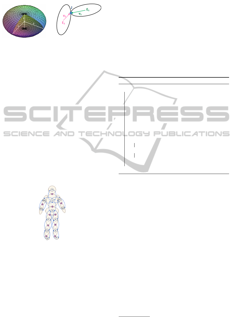
(a) (b)
Figure 1: Appearance model - (a) ellipsoidal geometric
shape; (b) joint J between two connected ellipsoids (2D
simplified representation).
objects’ rigid parts (ellipsoids), while the edges corre-
spond to the connections between such parts (joints).
Applying this model over the appearance model turns
the deterministic ellipsoids’ positions, orientations
and connections into flexible probabilistic beliefs. An
example of Loose-Limbed model can be seen in Fig-
ure 2.
Sigal (Sigal et al., 2003) compare this model with
a ”toy push puppet” with elastic joints: one part of the
object pulls and pushes the adjacent parts, but them
does not need to be exactly glued. Thus, certain flex-
ibility is achieved, however the object movements are
still restricted. This model allows, in the context of
motion tracking, changes over the objects’ parts con-
nections. Corrections in the representation model are
possible when, for instance, two parts are erroneously
considered dependent on a first moment, and found
not physically connected in a second instant. The
vice-versa situation can also be corrected.
Figure 2: Probabilistic graphical model - rigid parts and
their connections.
5 VOLUME GEOMETRIC
DECOMPOSITION METHOD
This method constructs representation models of dis-
tinct and a priori unknown objects from a volumetric
reconstruction of them. It divides the set of occupied
voxels in geometric shapes (ellipsoids, in the present
proposal), so that, within each shape, a minimum
quantity of empty space remains. Firstly, a connected
component (connected group of voxels) is identified
through a breadth-first search; next, the voxels posi-
tion mode of this component is calculated; then an
ellipsoid is expanded from the voxel nearest to the
position mode, so that the percentage of unoccupied
voxels (not occupied by any object) within the ellip-
soid is kept as small as possible. The found ellipsoid
must enclose a minimum number of occupied voxels
to be considered as a valid object’s part, otherwise it
is disregarded. The process is repeated until all voxels
have been analyzed. Algorithm 1 shows the method
pseudo-code and their main subroutines are detailed
in the next subsections.
Algorithm 1: A Volume Geometric Decomposition.
While there is non analyzed voxels
Identify Connected Component of
voxels
Identify the Nearest Voxel to the con-
nected component position mode
Expand a New Ellipsoid from the
nearest voxel
Mark the already analyzed voxels
If the number of ellipsoid’s voxels >
threshold
Accept the new ellipsoid
Else
Discard the new ellipsoid
End If
End While
a) Identify Connected Component: from a non ana-
lyzed and occupied voxel v this subroutine executes a
breadth-first search for voxels that fulfill the following
requisites: i) to be occupied; ii) not to be previously
analyzed; iii) not to be associated to any other ellip-
soid. All the connected voxels that meet these condi-
tions are assigned to the same connected component.
b) Identify the Nearest Voxel: into this subroutine
the position mode M
o
of the voxels connected com-
ponent is calculated
1
and after that, the nearest voxel
is identified. The mode was chosen among the geo-
metric center and the median of the volume because
it was the most effective to kept the ellipsoid’s center
way from volume borders.
c) Expand a New Ellipsoid: In order to expand a
new ellipsoid, firstly, is defined that only the occu-
pied voxel closest to the mode belongs to the ellip-
soid. Then, a breadth-first search is performed from
this voxel, adding one level of the search at a time.
At each new added level, the ellipsoid that covers all
the added occupied voxels is recalculated. Next, all
the occupied voxels that are inside the obtained shape
1
The mode is separately calculated for each dimension
x, y and z.
VISAPP2013-InternationalConferenceonComputerVisionTheoryandApplications
276
and that have not yet been assigned to any ellipsoid
are also associated. Then, the new central voxel of
the ellipsoid is determined. This is employed to move
the center of the ellipsoid to a position more favor-
able to their growth (thus, the ellipsoid moves toward
the object volume and, consequently, it can include a
greater number of voxels). The process is continued
until the ellipsoid stops to grown for a certain number
of iterations or whether it became invalid. An ellip-
soid is considered invalid if this rate of empty voxels
within the shapes is greater than a certain threshold.
The two subroutines that compose the process are de-
tailed in the following subsections.
c.1) Update Ellipsoid’s Parameters: this method re-
ceives a set of occupied voxels V
E
and calculates the
shape of the ellipsoid E that encloses those voxels.
Initially, the mean position and the covariance matrix
are calculated. Next, the singular value decomposi-
tion of the covariance matrix is employed to obtain the
principal axes of the ellipsoid (~a,
~
b e ~c). The eigen-
vectors of the covariance matrix correspond to the di-
rections of the axes and the eigenvalues correspond to
the modules of these axes (Ban
´
egas et al., 2001).
c.2) Check Ellipsoid’s Validity: the obtained ellip-
soid must present a minimal size in each one of their
principal axes. To correct the shapes in which the co-
variance matrix has not this minimal variation in the
direction of the main axes, new values are assigned
to the axes considered inappropriated. Three cases
are considered according to the number of axes which
have module less than the threshold:
1. three axes - a standard ellipsoid with minimum
size is assigned;
2. two axes - only the direction and the module of
one axis is known, so let
~
A be the known axis,
the other two axes must be orthogonal to
~
A and
between themselves. An arbitrary vector
−−−→
ncol
A
is
calculated. Then, from the cross product,
~
B =
~
A ×
−−−→
ncol
A
, a vector
~
B orthogonal to
~
A is obtained. The
third vector is obtained as
~
C =
~
A ×
~
B;
3. one axis - let
~
A and
~
B be the known axes, the di-
rection of the unknown axis is given by
~
C =
~
A×
~
B.
A final ellipsoid’s parameters adjustment is re-
quired, specially when the voxels are not uniformly
distributed inside the shape. This adjustment changes
the main axes modules, but not their directions pre-
viously obtained. To do so, the rotation matrix that
aligns the ellipsoid principal axes parallel to the coor-
dinate axes is calculated. The same rotation is applied
to the position vectors
−→
P
v
of each voxel v inside the el-
lipsoid E, obtaining the vectors
−→
P
vr
. The constants a,
b and c are calculated as follow:
a = (maximum(P
vr
x
) − minimum(P
vr
x
))/2,
b = (maximum(P
vr
y
) − minimum(P
vr
y
))/2,
c = (maximum(P
vr
z
) − minimum(P
vr
z
))/2,
(1)
where maximum and minimum concerns all voxels
values. Finally, we define the module of the new prin-
cipal axes of the ellipsoid (~a
n
,
~
b
n
e ~c
n
) as follows:
~a
n
= a ∗
~a
|~a|
,
~
b
n
= b ∗
~
b
|
~
b|
, ~c
n
= c ∗
~c
|~c|
.
(2)
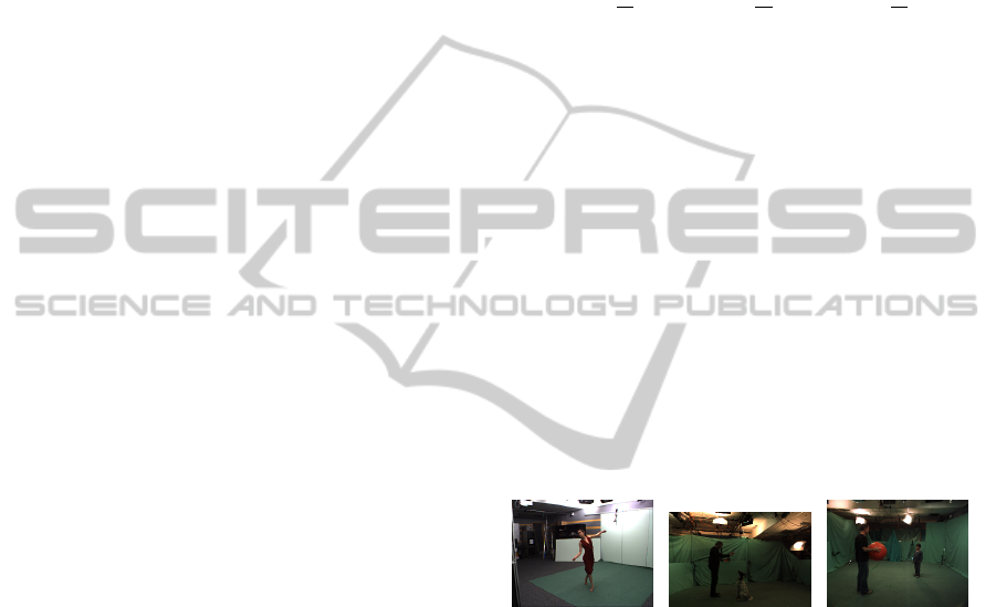
6 EXPERIMENTS AND RESULTS
The experiments were performed with three differ-
ent image sequences, obtained in a public benchmark
dataset (Inria, 2012). Each one of the sequences is
composed by images captured by multiple synchro-
nized and calibrated cameras along a period of time.
From a set of images, captured at the same time in-
stant, a probabilistic volumetric reconstruction is built
(Franco and Boyer, 2005). The objects representation
model is then constructed over this volumetric recon-
struction through the Volume Geometric Decomposi-
tion method. Samples of the images sequences are
shown in the Figure 3, while samples of the volumet-
ric reconstruction is shown in the Figure 4.
(a) (b) (c)
Figure 3: Samples of the benchmark image sequences
Dance, Dog and Child. Each sequence was captured by
8, 16 and 16 cameras, respectively, during a period of time.
(a) One of the eight images from the Dance sequence. (b)
One of the sixteen images from the Dog sequence. (c) One
of the sixteen images from the Child sequence.
The Figures 5, 6 and 7 presents the representa-
tion models for the time instant t = 0 of the sequence
Dance, Dog and Child, respectively. The minimum
size of the ellipsoids was equal to 15 voxels, while the
threshold for the accepted rate of unoccupied voxels
enclosed by the shapes was 0.3.
The presented results shown the construction of
representation models for different kinds of objects:
adult humans, a child, a dog and balls. Such bench-
mark is considered by the authors sufficiently general
to test the proposed method, intended to be capable of
building representation models for distinct and a pri-
ori unknown objects.
3DRepresentationModelsConstructionthroughaVolumeGeometricDecompositionMethod
277
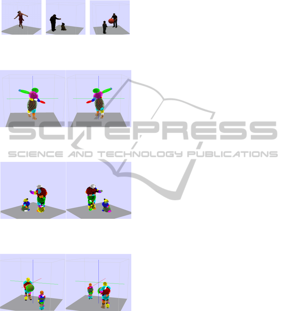
(a) (b) (c)
Figure 4: Samples of probabilistic volumetric reconstruc-
tion of the benchmark sequences (a) Dance, (b) Dog and
(c) Child.
Figure 5: Representation model obtained by Volume Geo-
metric Decomposition method. Image sequence Dance at
time t = 0 - the ellipsoids are expanded from the connected
components modes.
Figure 6: Representation model obtained by Volume Ge-
ometric Decomposition method. Image sequence Dog at
time t = 0 - the ellipsoids are expanded from the connected
components modes.
Figure 7: Representation model obtained by Volume Ge-
ometric Decomposition method. Image sequence Child at
time t = 0 - the ellipsoids are expanded from the connected
components modes.
It can be seen that the Volume Geometric Decom-
position method could successfully built the represen-
tation model to all objects in the sequences, adjust-
ing the ellipsoids to the volumetric reconstruction and
keeping the number of unoccupied voxels inside the
geometric shapes as small as possible. The method
could correctly identify some objects’ rigid parts, as
the humans’ and dog’s heads, the humans’ thoraces
and the ball. In other points, as the arms of the dancer
(Figure 5), the method correctly identified two rigid
parts in the left arm, but erroneously detected the right
arm as just one rigid object. The child, in the Child se-
quence (Figure 7), and the man, in the Dog sequence
(Figure 6), appear with their legs put together, what
generates some noise in the volumetric reconstruction
and consequently the existence of many small ellip-
soids representing that volumes.
7 CONCLUSIONS
This work present as the main contribution a novel
method, named Volume Geometric Decomposition,
to the automatic construction of objects representa-
tion models from volumetric reconstructions, in the
context of a 3D motion tracking framework. The em-
ployed representation model is composed by an ap-
pearance model and a kinematic model. The former
is comprised of ellipsoids and joints, while the lat-
ter is implemented through a Loose-Limbed model,
a probabilistic graphical model, which turns the de-
terministic position and orientation parameters of the
ellipsoids and joints into probabilistic beliefs.
The Volume Geometric Decomposition method
adjusts the ellipsoids to the volumetric reconstruction
and kept the number of unoccupied voxels inside the
geometric shapes as small as possible. As could be
seen in the results of the experiments, the method
successfully achieved this goal. It was capable of
representing all objects volumes. Despite some rigid
parts and joints have not been correctly identified, the
adopted Loose-Limbed model approach aims, in the
context of the motion tracking framework, the pos-
terior refinement of the initially found representation
models. This could be accomplished by the use of the
Nonparametric Belief Propagation (NBP) technique
(Sudderth et al., 2003), (Sudderth et al., 2010) and
the PArticle Message PASsing (PAMPAS) algorithm
(Isard, 2003).
As future works, some points must be explored.
A quantitative metric to evaluate the representation
model quality, in terms of volume representation, is
desired. The comparison between this approach and
clustering algorithms is also highly recommended.
Finally, the refinement of the representation mod-
els, through the NBP and PAMPAS algorithms is ex-
tremely important, once it justifies the Loose-Limbed
model adoption.
VISAPP2013-InternationalConferenceonComputerVisionTheoryandApplications
278

REFERENCES
Anguelov, D., Koller, D., Pang, H.-C., Srinivasan, P., and
Thrun, S. (2004). Recovering articulated object mod-
els from 3d range data. In 20th Conf. on Uncertainty
in Artificial Intelligence, UAI ’04, pages 18–26.
Ban
´
egas, F., Jaeger, M., Michelucci, D., and Roelens, M.
(2001). The ellipsoidal skeleton in medical applica-
tions. In Sixth ACM Symp. on Solid Modeling and
Appl., SMA ’01, pages 30–38.
Caillette, F. (2006). Real-Time Markerless 3D Human Body
Tracking. Phd thesis, University of Manchester.
Canton-Ferrer, C., Casas, J., and Pardas, M. (2009). Voxel
based annealed particle filtering for markerless 3d ar-
ticulated motion capture. In 3DTV Conf.: The True Vi-
sion - Capture, Transmission and Display of 3D Video,
2009, pages 1 –4.
Cipolla, R., Stenger, B., Thayananthan, A., and Torr, P.
(2003). Hand tracking using a quadric surface model
and bayesian filtering. In Mathematics of Surfaces,
volume 2768 of LNCS, pages 129–141. Springer.
Darby, J., Li, B., and Costen, N. (2008). Behaviour based
particle filtering for human articulated motion track-
ing. In ICPR, 2008, pages 1–4.
de Aguiar, E., Theobalt, C., Magnor, M., Theisel, H., and
Seidel, H.-P. (2004). M3: marker-free model recon-
struction and motion tracking from 3d voxel data. In
Pacific Graphics, 2004, pages 101–110.
de Aguiar, E., Theobalt, C., and Seidel, H.-P. (2006). Auto-
matic learning of articulated skeletons from 3d marker
trajectories. In Second Int. Conf. on Advances in Vi-
sual Computing, ISVC’06, pages 485–494.
de Aguiar, E., Theobalt, C., Thrun, S., and Seidel, H.-P.
(2008). Automatic conversion of mesh animations
into skeleton-based animations. Computer Graphics
Forum, 27(2):389–397.
Fossati, A., Salzmann, M., and Fua, P. (2009). Observable
subspaces for 3d human motion recovery. In CVPR,
2009, pages 1137–1144.
Franco, J.-S. and Boyer, E. (2005). Fusion of multiview
silhouette cues using a space occupancy grid. In ICCV,
2005, pages 1747–1753.
Gall, J., Rosenhahn, B., Brox, T., and Seidel, H.-P. (2010).
Optimization and filtering for human motion capture.
Int. J. of Computer Vision, 87:75–92.
Hasler, N., Rosenhahn, B., Thormahlen, T., Wand, M., Gall,
J., and Seidel, H.-P. (2009). Markerless motion cap-
ture with unsynchronized moving cameras. In CVPR,
2009, pages 224–231.
Huang, P., Hilton, A., and Starck, J. (2009). Human motion
synthesis from 3d video. In CVPR, 2009, pages 1478–
1485.
Inria (2012). 4d repository. Perception Group, Inria Rh
ˆ
one-
Alpes. http://4drepository.inrialpes.fr.
Isard, M. (2003). Pampas: real-valued graphical models for
computer vision. In CVPR, 2003, pages 613–620.
James, D. L. and Twigg, C. D. (2005). Skinning mesh ani-
mations. ACM Trans. Graph., 24(3):399–407.
Mian, A., Bennamoun, M., and Owens, R. (2006). Three-
dimensional model-based object recognition and seg-
mentation in cluttered scenes. IEEE Trans. Pattern
Anal. Machine Intell., 28(10):1584 –1601.
Miki
´
c, I., Trivedi, M., Hunter, E., and Cosman, P. (2003).
Human body model acquisition and tracking using
voxel data. Int. J. of Computer Vision, 53:199–223.
Ross, D., Lim, J., Lin, R.-S., and Yang, M.-H. (2008). In-
cremental learning for robust visual tracking. Int. J. of
Computer Vision, 77:125–141.
Ross, D., Tarlow, D., and Zemel, R. (2010). Learning ar-
ticulated structure and motion. Int. J. of Computer
Vision, 88:214–237.
Schaefer, S. and Yuksel, C. (2007). Example-based skeleton
extraction. In Fifth Eurographics Symp. on Geometry
Processing, SGP ’07, pages 153–162.
Sigal, L. and Black, M. (2010). Guest editorial: State of the
art in image- and video-based human pose and motion
estimation. Int. J. of Computer Vision, 87:1–3.
Sigal, L., Isard, M., Sigelman, B. H., and Black, M. J.
(2003). Attractive people: Assembling loose-limbed
models using non-parametric belief propagation. In
NIPS, 2003, pages 1539–1546.
Song, Y., Goncalves, L., and Perona, P. (2003). Unsuper-
vised learning of human motion. IEEE Trans. Pattern
Anal. Machine Intell., 25(7):814 – 827.
Starck, J. and Hilton, A. (2003). Model-based multiple view
reconstruction of people. In ICCV, 2003, pages 915–
922.
Starck, J. and Hilton, A. (2007). Surface capture for
performance-based animation. IEEE Comput. Graph.
Appl., 27:21–31.
Sudderth, E., Ihler, A., Freeman, W., and Willsky, A.
(2003). Nonparametric belief propagation. In CVPR,
2003., pages 605–612.
Sudderth, E. B., Ihler, A. T., Isard, M., Freeman, W. T., and
Willsky, A. S. (2010). Nonparametric belief propaga-
tion. Commun. ACM, 53(10):95–103.
Sundaresan, A. and Chellappa, R. (2009). Multicamera
tracking of articulated human motion using shape and
motion cues. IEEE Trans. on Image Processing,
18(9):2114 –2126.
Theobalt, C., de Aguiar, E., Magnor, M. A., Theisel, H.,
and Seidel, H.-P. (2004). Marker-free kinematic skele-
ton estimation from sequences of volume data. In
ACM Symp. on Virtual Reality Software and Technol-
ogy, 2004, VRST ’04, pages 57–64. ACM.
Toshev, A., Makadia, A., and Daniilidis, K. (2009). Shape-
based object recognition in videos using 3d synthetic
object models. In CVPR, 2009, pages 288 –295.
Ukita, N., Hirai, M., and Kidode, M. (2009). Complex vol-
ume and pose tracking with probabilistic dynamical
models and visual hull constraints. In ICCV, 2009,
pages 1405 –1412.
3DRepresentationModelsConstructionthroughaVolumeGeometricDecompositionMethod
279
