
3D Invariants from Coded Projection without Explicit Correspondences
Kenta Suzuki, Fumihiko Sakaue and Jun Sato
Department of Computer Science, Nagoya Institute of Technology, Nagoya, Japan
Keywords:
3D Object Recognition, 3D Invariants, Projector-camera Systems, Coded-projection.
Abstract:
In this paper, we propose a method for computing stable 3D features for 3D object recognition. The feature
is projective invariant computed from 3D information which is based on disparity of two projectors. In our
method, the disparity can be estimated just from image intensity without obtaining any explicit corresponding
points. Thus, we do not need any image matching method in order to obtain corresponding points. This means
that we can avoid any kind of problems arise from image matching essentially. Therefore, we can compute
3D invariant features from the 3D information reliably. The experimental results show our proposed invariant
feature is useful for 3D object recognition.
1 INTRODUCTION
3D Object recognition is one of the most impor-
tant problems in computer vision. The method can
be applied to various kinds of applications, such as
robot vision, visual surveillance and so on, and thus,
the method is studied extensively(Murase and Na-
yar, 1995; Lowe, 1999; Hetzel et al., 2001; To-
shev et al., 2009). The recognition method can be
classified into two methods, that is appearance-based
method(Murase and Nayar, 1995; Lowe, 1999) and
3D shape-based method(Hetzel et al., 2001; Toshev
et al., 2009). The appearance based method is more
familiar than shape-based method because we need
only cameras in order to construct object recogni-
tion system. However, appearance of target object
dramatically changes when viewpoint of camera is
changed. Therefore, we need large number of images
for achieving stable object recognition.
On the other hand, object shapes provide 3D in-
formation directly which is independent from view
point. Thus, shape-based method is more stable than
appearance-based method in general. However, we
should obtain 3D information of target object by us-
ing some kind of sensors. In ordinary case, object
shape is reconstructed from images taken by stereo
cameras(Hartley and Zisserman, 2000). In this case,
we first search corresponding points from stereo im-
ages. We next reconstruct object shape from the cor-
responding points. Although we can obtain 3D shape
accurately when the corresponding points are correct,
reconstructed shape is not correct if there are some
incorrect corresponding points. Although many kinds
of methods were proposed in order to find correct
corresponding points, we cannot essentially avoid the
corresponding problem in stereo camera systems, and
wrong correspondences are always included in the re-
sults.
Another standard method for obtaining 3D shape
is to use projector-camera systems(Caspi et al., 1998;
Zhang et al., 2002; Vuylsteke and Oosterlinck, 1990;
Proesmans et al., 1996; Boyer and Kak, 1987). In
this method, feature points are projected onto target
objects from a projector and the projected points are
observed by a camera. By using the correspondences
between projected point and observed point, we can
reconstruct 3D shape as same as stereo camera sys-
tems. This method is preferable when we want to ob-
tain object shape accurately because this active sys-
tem is more stable than ordinary passive stereo cam-
era systems. In addition, the system can reconstruct
3D shape even if a target object does not have any
textures on surface of the object. However, the active
system also suffers from wrong corresponding points
if object texture is complex. Thus, we cannot avoid
corresponding point problem again.
In order to avoid the wrong correspondence prob-
lem, Sakaue and Sato(Sakaue and Sato, 2011) pro-
posed coded projection, which uses two projectors for
recovering 3D shape of objects. In this method, we do
not need to search corresponding points, and thus, we
can essentially avoid the wrong correspondence prob-
lem in 3D shape recovery. However, their method is
not sufficient to obtain accurate 3D shape because the
main purpose of their method is not shape reconstruc-
tion but shape visualization, and, they did not con-
286
Suzuki K., Sakaue F. and Sato J..
3D Invariants from Coded Projection without Explicit Correspondences.
DOI: 10.5220/0004289802860293
In Proceedings of the International Conference on Computer Vision Theory and Applications (VISAPP-2013), pages 286-293
ISBN: 978-989-8565-48-8
Copyright
c
2013 SCITEPRESS (Science and Technology Publications, Lda.)
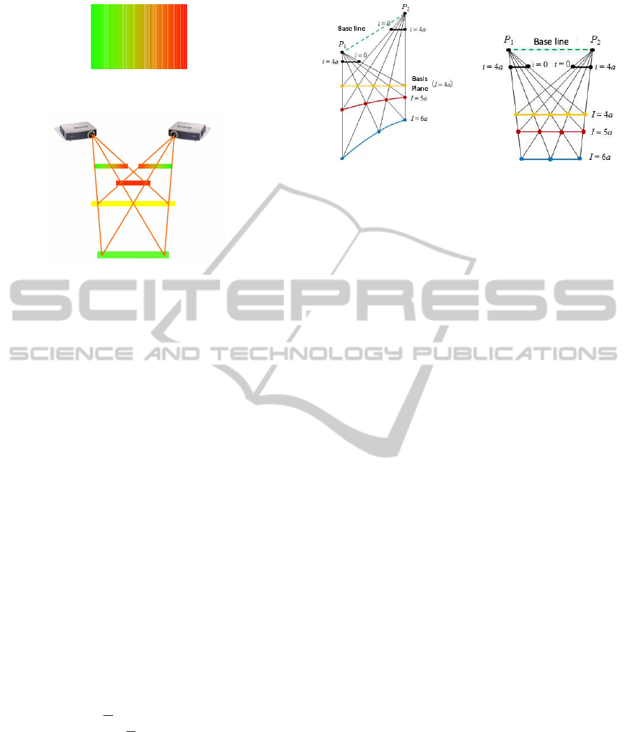
Figure 1: Projected images. Intensities of red and green are
horizontally varied and intensity of blue is fixed.
Figure 2: Coded projection from two projectors. Distance
between projectors to object is visualized by color. Near
objects from projectors are colored by red and far objects
from projectors are colored by green.
sider reflectance property and normal direction of ob-
ject surface. In this paper, we analyze the detail prop-
erty of coded projection and propose a method for ob-
taining accurate and stable 3D information without
any corresponding points search. Furthermore, we
derive 3D invariants for 3D object recognition from
measurement results.
2 VISUALIZATION OF DEPTH
USING CODED PROJECTION
2.1 Depth Visualization
We first explain depth visualization by coded projec-
tion from multiple projectors(Sakaue and Sato, 2011).
In this method, coded patterns are projected from two
projectors to target objects simultaneously. Figure 1
shows projected patterns for depth visualization. In
this image, intensities of red and green are horizon-
tally variedand intensities of blue are fixed as follows:
I
R
=
x
W
I
G
= 1 −
x
W
I
B
= 0
(0 ≤ x ≤ W) (1)
where I
R
,I
G
and I
B
are intensities of each colors, x is
horizontal axis, and W is the width of the image. The
range of each intensity is 0 ∼ 1.
As shown in Fig. 2, the left projector projects
Fig.1 and the right projector projects a reversed im-
age. Then, projected images from the both projectors
are combined on the surfaces of object in the scene.
(a) (b)
Figure 3: Distortion of depth visualization: Depth visual-
ization is distorted when the base line and the basis plane is
not parallel to each other as shown in Fig.(a). When the base
line and the basis plane is parallel to each other, distortion
of visualization.is eliminated.
As a result, depth of the scene is visualized as shown
in Fig.2.
In this scene, near points are colored by red, mid-
dle points are colored by yellow and far points are
colored by green. This visualization is caused by dis-
parity of two projectors. For example, if the disparity
is equal to zero, the projected images are completely
overlapped, i.e., red colors lie onto green color and
green colors lie onto red colors, and we can observe
yellow colors. Therefore, we can visualize distance
from projectors to a target as color information. The
coloring of object point is based on the distance from
yellow plane to the object point. We can change vi-
sualization of scene by controlling the plane. In this
paper, we call the plane as basis plane for coded pro-
jection.
2.2 Arrangement of Basis Plane
In order to visualize depth information correctly, we
have to parallelize the base line of two projectors and
the basis plane. Let us consider a case where the
base line is not parallel to the basis plane as shown
in Fig.3(a). In this case, the depth visualization is
distorted as shown by yellow, red and blue lines in
Fig.3(a). On the other hand, if we arrange two projec-
tors so that their base line is parallel to the basis plane,
the depth visualization is not distorted as shown in
Fig.3(b). Thus, in order to avoid the distortion prob-
lem, we should arrange the basis plane so that is is
parallel to the base line of projectors.
2.3 Visualization of Various 3D
Information
By changing the basis plane, we can visualize not
only depth but also other information such as height.
3DInvariantsfromCodedProjectionwithoutExplicitCorrespondences
287
Basis Plane
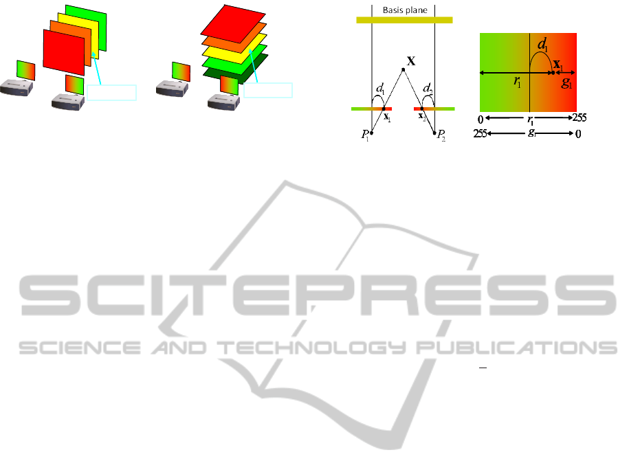
(a) Visualization of depth informa-
tion.
Basis Plane
(b) Visualization of height infor-
mation.
Figure 4: Changes of visualized information depends on ba-
sis plane: We can control visualized information by chang-
ing the basis plane. In figure (a), depth from projectors is
visualized. Height from the ground plane is visualized in
figure (b). The change in visualization can be achieved by
only changing the basis plane (yellow plane).
For example, depth from projectors are visualized by
coded projection. In Fig.4(a), while the height from
the ground plane is visualized in Fig.4(b). In order
to change visualizing information, we should simply
change direction of the basis plane. For example, we
can visualize height when the basis plane is parallel
to the ground plane.
As we showed in this section, the coded projec-
tion directly projects depth information to target ob-
ject. Thus, we can avoid some important problems
in stereo vision. First problem is the search of corre-
sponding points. In ordinary stereo system, we should
find corresponding point pair to estimate shape infor-
mation. However, explicit corresponding points are
not required in the coded projection because corre-
sponding points in projected images are automatically
combined and visualized by color on a target surface.
Second, we do not need any computation to visualize
depth because the depth is automatically represented
by combination of projected image. Thus, there is no
computational cost in the coded projection.
3 3D MEASUREMENT BY
CODED PROJECTION
3.1 Depth Computation by Coded
Projection
In the previous section, we showed depth visualiza-
tion by using coded projection. In this section, we
consider a method which can obtain accurate and sta-
ble 3D shape by using coded projection.
As shown in section 2, the coded projection can
visualize depth information by using color informa-
tion. Thus, we can obtain depth information from im-
age color. Let us consider a scene when two projec-
tors are fixed in a scene. The projectors project coded
(a) (b)
Figure 5: Relationship between disparity and depth. Figure
(a) indicates disparity d
1
and d
2
for a 3D point X and (b)
indicates the relationship between color information and the
disparity d.
patterns to target objects as shown in Fig. 5. In this
case, we can represent disparity d of two projectors
by using d
1
and d
2
as follows:
d = d
1
+ d
2
(2)
In general, depth D from projectors can be estimated
by a disparity d as follows:
D =
1
d
(3)
This equation indicates that we can estimate depth
from disparity.
Under coded projection, we can simply obtain dis-
parity between two projectors because color informa-
tion directly represents disparity. Let us consider a
scene as shown in Fig.5. In this scene, image points
x
1
and x
2
are projected onto 3D point X. Projected
colors on a point x
1
is described by r
1
,g
1
, and r
2
,g
2
describe colors for point x
2
. In this case, irradiance
R,G and B for X can be described as follows:
R = r
1
+ r
2
G = g
1
+ g
2
B = 0
(4)
From Eq.(1), r
1
and g
1
can be represented by d
1
as
follows:
r
1
= d
1
+ 0.5
g
1
= 0.5− d
1
(5)
Similarly, r
2
and g
2
can be described by d
2
as follows:
r
2
= d
2
+ 0.5
g
2
= 0.5− d
2
(6)
From these equations, irradiance R, G and B can be
rewritten as follows:
R = d
1
+ d
2
+ 1
G = 1− (d
1
+ d
2
)
B = 0
(7)
Thus, we can obtain a disparity d from colors as fol-
lows:
VISAPP2013-InternationalConferenceonComputerVisionTheoryandApplications
288

2d = 2(d
1
+ d
2
) = R− G (8)
This equation indicates that we can measure object
depth from irradiance of projectors. We do not need
any complex method which provides corresponding
points for stereo matching. We should only need to
project coded image from projectors to a target object
in order to obtain 3D information.
3.2 Irradiance Estimation from Images
We described a direct depth measuring method from
projected irradiance in section 3.1. The method has
large advantageto ordinary stereo method because we
can avoid correspondences problem in stereo match-
ing. We, however, cannot obtain 3D information from
ordinary input images because we can observe not
irradiance but intensity from images. The intensity
includes not only the effect of irradiance but also
albedo, surface normal and so on. Thus, we have to
extract magnitude of irradiance from input images to
measure 3D information.
In general, most part of object surface can be ap-
proximately modeled by Lambertian surface model.
We assume that reflectance model for all object sur-
faces can be represented by the Lambertian model.
Therefore, observed intensities I
R
, I
G
and I
B
on 3D
point X illuminated by a projector P can be described
as follows:
I
R
I
G
I
B
=
n
⊤
(X− P)
||X− P||
3
rρ
R
gρ
G
bρ
B
, (9)
where ρ
R
,ρ
G
,ρ
B
and r, g and b denote albedo and ir-
radiance for each channels, n and P indicate normal
direction on a target surface and optical center of a
projector. In this equation, ||X−P|| indicates distance
from a projector to an object surface and division by
||X−P||
2
indicates irradiance attenuation by distance.
Equation(9) indicates that we have to know albedo
of the surface, distance from projector and surface
normal in order to estimate irradiance. Although esti-
mation of these parameters from an input image is ill-
posed problem, we can simply estimate these param-
eters from a particular image under a particular pro-
jected image. In this method, we can control lighting
condition because light sources in the scene are pro-
jectors, and then, we can generate arbitrary lighting
condition to obtain these parameters. Let us consider
a case where a white image (r = g = b = 1) is pro-
jected by a projector. In this case, observed intensities
I
RW
,I
GW
and I
BW
can be represented as follows:
I
RW
I
GW
I
BW
=
n
⊤
(X− P)
||X− P||
3
ρ
R
ρ
G
ρ
B
. (10)
If an optical center P is fixed, observed intensities di-
rectly represent effects of albedo, irradiance attenu-
ation and normal direction in Eq.(9). Therefore, we
can directly estimate irradiance in Eq.(9) as follows:
r
g
b
=
I
R
/I
RW
I
G
/I
GW
I
B
/I
BW
. (11)
The estimation should be done for each projector, re-
spectively. Then, depth D can be computed from irra-
diance r and g as follows:
D =
2
(r
1
+ r
2
) − (g
1
+ g
2
)
(12)
where r
i
and g
i
denote irradiance of i-th projector es-
timated by Eq.(11).
4 PROJECTIVE INVARIANTS
FOR 3D OBJECT
RECOGNITION
4.1 3D Projective Invariants from
Feature Points
From the estimated irradiance, we can obtain 3D in-
formation about target objects without explicitly ob-
taining stereo correspondences. It however includes
projective ambiguity because relationship between
two projectors is not explicitly calibrated. There-
fore, we should consider this ambiguity to realize
calibration-free 3D object recognition. In this section,
we show two different methods to cope with this am-
biguity.
We first explain a method which computes 3D
projective invariants from 3D information. The cross
ratio of 3D volumes is well known invariant under
projective ambiguity. The invariant I can be estimated
as follows:
I =
|
e
Y
1
e
Y
2
e
Y
3
e
Y
4
||
e
Y
6
e
Y
2
e
Y
3
e
Y
5
|
|
e
Y
1
e
Y
2
e
Y
3
e
Y
5
||
e
Y
6
e
Y
2
e
Y
3
e
Y
4
|
, (13)
where Y
i
indicate 3D information of i-th point under
coded projection, which is computed from depth D
i
and image point coordinate x
i
as follows:
Y
i
= D
i
˜
x
i
(14)
A symbol
˜
(·) denotes homogeneous representation.
The invariant is independent from projective transfor-
mation of 3D scene, and thus, we can describe 3D ob-
jects uniquely even if measured information includes
projective ambiguity.
3DInvariantsfromCodedProjectionwithoutExplicitCorrespondences
289
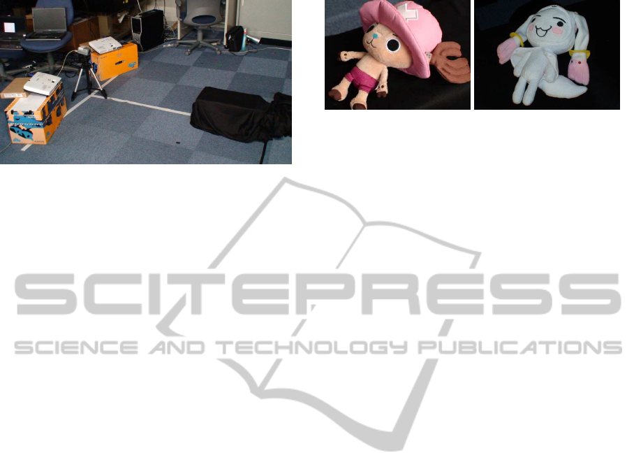
Projector1
Projector2
Camera
Figure 6: Experimental environment.
4.2 3D Invariant Image
The invariant described in previous section depends
on image feature points. This invariant is very con-
venient when we can obtain sparse 3D information
from input images. We however can obtain dense 3D
information under coded projection easily, and thus,
we should consider a method which uses dense infor-
mation of images.
Under coded projection, complete depth map can
be obtained up to projective ambiguity. Thus, we can
transform images from a view point to another view-
point by using projective transformation. A projective
transformation H
4×4
can be described as follows:
λ
˜
Y
′
= H
4×4
˜
Y. (15)
where λ denotes scale ambiguity, and, Y and Y
′
de-
note 3D points including projective ambiguity. The
projective transformation can be estimated from 5 or
more than 5 pairs of corresponding points. Then, we
can transform all image points to another viewpoint
by using the projective transformation. The trans-
formed images are taken from the same viewpoint vir-
tually, and thus, we can recognize the object by using
ordinary 2D pattern recognition method without con-
sidering the difference in pose.
5 EXPERIMENTAL RESULTS
5.1 Environment
In this section, we show some experimental results
from our proposed method. In these experiments, two
projectors and a camera are fixed as shown in Fig.6.
In this scene, a camera is fixed onto base line be-
tween two projectors. Coded patterns are projected
from these projectors and target objects are illumi-
nated by them. As a coded pattern for depth visu-
alization, the image shown in Fig.1 was used. Target
objects are shown in Fig.7. The objects are fixed on
(a) target(A) (b) target(B)
Figure 7: Target objects.
a stand in the experimental scene, and measured in 4
different poses, respectively. We show observed re-
sult and computed invariants in the next section.
5.2 Measurement Results
Figure8 shows the result from coded projection for a
target(A). The image (a) and (c) in Fig. 8 were taken
under coded pattern and white pattern from projec-
tor1 respectively. As shown in image (a), the image
intensity is affected by not only irradiance of projec-
tor but also albedo, normal direction and so on. On
the other hand, image (c) includes only normal direc-
tion and albedo. From these images, image (e) was
computed by Eq.(11). This image includes only irra-
diance because other components were eliminated by
Eq.(11). Similarly, image (b) and (d) were taken un-
der coded pattern and white pattern projected from
projector2, and (f) is the estimated irradiance from
(b) and (d). The image (g) is combined image of
(e) and (f). In this image, subtractions of green from
red components represent disparity between projec-
tor1 and projector2. For example near points from
projectors, such as nose and foot, were colored by red.
On the other hand, far points were colored by green.
Finally, the image (h) represents depth from projec-
tors computed by Eq.(3). In this image, near points
are represented by dark intensity and far points are
represented by bright intensity. From the disparity im-
age, we can obtain 3D information without using any
stereo matching method. Therefore, estimated depth
is much more reliable than ordinary stereo reconstruc-
tion method based on feature point matching. In ad-
dition, we need very small computational cost for ob-
taining 3D information.
Note that, some points which has dark albedo can-
not be measured correctly in this image because we
cannot observe sufficient intensity onto the points.
However, this disadvantage also exists on ordinaryac-
tive stereo method because we cannot project/observe
feature points onto darker pixels.
VISAPP2013-InternationalConferenceonComputerVisionTheoryandApplications
290
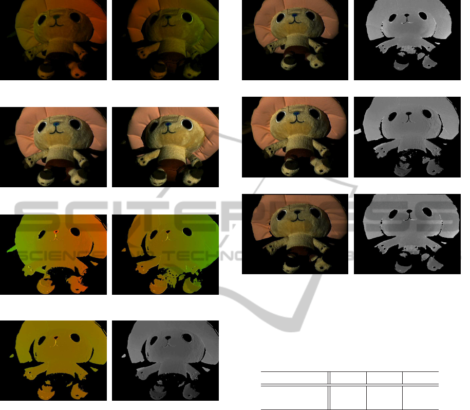
(a) Observed intensity under coded
pattern for projector1
(b) Observed intensity under coded
pattern for projector2
(c) Observed intensity under white
image for projector1
(d) Observed intensity under white
image for projector2
(e) Estimated irradiance for projec-
tor1
(f) Estimated irradiance for projec-
tor2
(g) Colored disparity image (h) Depth image
Figure 8: Measured results under coded projections. Image
(a) and (b) were taken under coded pattern from projector1
and 2, (c) and (d) were taken under white pattern, and, (e)
and (f) are estimated irradiance. The image (g) is a com-
bined image of (e) and (f), and the image (h) is a depth map
computed from the inverse of image (g).
5.3 3D Invariants from Images
We next show 3D invariants estimated from Fig.8(h)
by using the proposed method. At first, we show
3D invariant images described in section 4.2. In this
experiment, we measured a target object in different
poses. One of the measured result is shown in Fig.9
(a) and (b). Figure9(a) shows an image taken un-
der white projection, and Fig.9(b) shows a measured
depth. The results from another pose are shown in
Fig.9 (c) and (d). In image (a) and image (c), fea-
ture point pairs were extracted by SIFT(Lowe, 1999),
(a) Observed intensity in pose1 (b) Measured depth in pose1
(c) Observed intensity in pose2 (d) Measured depth in pose2
(e) Transformed image (f) Transformed depth
Figure 9: Virtual viewpoint transformation: Images (a) and
(b) are images taken under white projection and a measured
depth in pose1. Images (c) and (d) arethose in pose2. Image
(e) and (f) show image intensity and depth in pose2 trans-
formed from pose1.
Table 1: Deference of invariants on each pose.
pose2 pose3 pose4
Difference of 0.002 0.027 0.044
3D invariant
and then, projective transformation in Eq.(15) was es-
timated by using the point pairs of depth map(b) and
(d). By using the estimated transformation and depth
images, image (a) and (b) were transformed to image
(e) and (f) whose pose coincides with that of image
(c) and (d) on pose 2. Although the original images
(a) and (c) are different from each other, the trans-
formed image (e) is almost identical with (c), and we
can use them for recognizing objects under different
viewpoints. Figure 10 shows results from target (B).
As shown in these figures, we can also virtually trans-
form images from a viewpoint to another viewpoint
by our proposed method. We next show point-based
3D invariant computed by Eq. (13). At first target A
was measured in 4 different poses and corresponding
points were extracted by SIFT as same as the previous
experiment. By using the points, 3D invariants were
computed in each pose. Table 1 shows difference of
invariants from pose1 to another pose.
3DInvariantsfromCodedProjectionwithoutExplicitCorrespondences
291
(a) Observed intensity in pose1 (b) Measured depth in pose1
(c) Observed intensity in pose2 (d) Measured depth in pose2
(e) Transformed image (f) Transformed depth
Figure 10: Virtual viewpoint transformation: Images (a)
and (b) are images taken under white projection and a mea-
sured depth in pose1. Images (c) and (d) are those in pose2.
Image (e) and (f) show image intensity and depth in pose2
transformed from pose1.
Table 2: Deference of invariants in each pose.
(A) \(B) pose1 pose2 pose3 pose4
pose1 27.722 4.380 - -
pose2 0.338 0.308 0.407 -
pose3 0.041 0.180 - -
pose4 - - - -
The table shows that our proposed invariants can
provide similar value even if measured objects have
different poses.
We next show difference of 3D invariants for dif-
ferent objects. In this experiment, target (A) and tar-
get (B) was measured in 4 different poses and corre-
sponding points were extracted by SIFT in images.
By using the points, 3D invariants were computed.
The difference of the invariants are shown in table 2.
In this table, a value of i-th row in j-th column indi-
cates difference of 3D invariantsbetween target (A) in
pose-i and target (B) in pose-j. In addition, “-” indi-
cates that we cannot extract corresponding point from
the image pair. In this table, almost all the difference
of 3D invariants are larger than those in table1. The
fact indicates that our proposed invariants can distin-
guish objects even if object poses are different each
other.
Camera
Projector1
Projector2
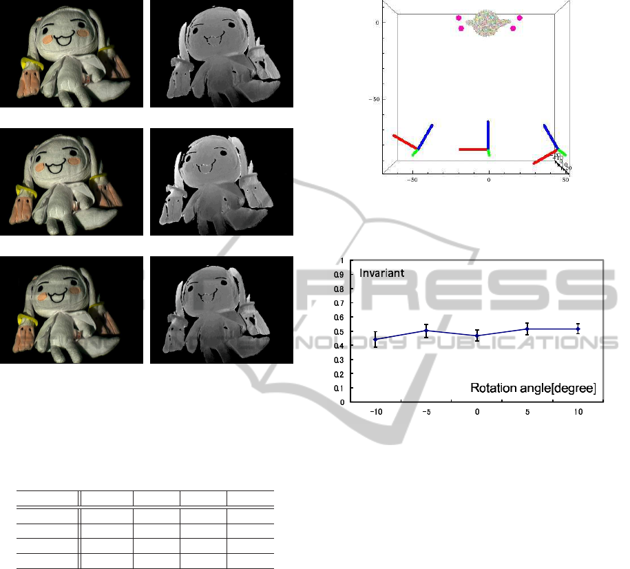
Figure 11: Synthesized environment: Red, green and blue
axis for a camera and projectors indicate optical axes of
them. Red points around a target object indicate basis plane
used for generating coded projector patterns.
Figure 12: Relationship between object pose and 3D invari-
ant. Horizontal axis indicates rotation angle of an object
and vertical axis indicates 3D invariant.
5.4 Stability Evaluation
We next show the stability of the proposed method by
using synthesized data. In this experiment, two pro-
jectors, a camera and a target object are arranged as
shown in Fig.11. The coded projection was observed
by the camera, and random intensity noise with STD
of 1.0 were added to the observed image.
The target object was rotated at the same posi-
tion, and, the 3D invariant described in Eq. (13) was
computed in each pose. Figure 8 shows computed in-
variants in each pose. The figure indicates that com-
puted invariants are stable even if pose of an object is
changed.
Figure 13 shows 3D invariant when the base line
length between two projectors was changed. In
this experiment, distance between two projectors was
changed from 40cm to 100cm. Under each base line
length, 3D invariants were computed for each pose.
Figure13 indicates that our proposed invariants are al-
most identical even if the base line length between
two projector was changed. The facts indicate that
our proposed method is robust against changing pose
and changing projectors positions.
VISAPP2013-InternationalConferenceonComputerVisionTheoryandApplications
292

Figure 13: Relationship between base line length and 3D
invariants.
6 CONCLUSIONS
In this paper, we proposed a 3D measurement method
based on disparity between two projectors. In this
method, we do not need to search image correspond-
ing points, and thus, we can avoid various kind of
problems such as wrong correspondences and com-
putational cost. In addition, we proposed method for
deriving 3D features which are invariant under pro-
jective ambiguity. We finally presented some experi-
mental results and showed that our proposed method
is useful for 3D object recognition.
REFERENCES
Boyer, K. L. and Kak, A. C. (1987). Color-encoded struc-
tured light for rapid active ranging. IEEE Trans. Pat-
tern Anal. Mach. Intell., 9(1):14–28.
Caspi, D., Kiryati, N., and Shamir, J. (1998). Range imag-
ing with adaptive color structured light. IEEE Trans.
Pattern Anal. Mach. Intell., 20(5):470–480.
Hartley, R. and Zisserman, A. (2000). Multiple View Geom-
etry in Computer Vision. Cambridge University Press.
Hetzel, G., Leibe, B., Levi, P., and Schiele, B. (2001). 3d
object recognition from range images using local fea-
ture histograms. In CVPR (2)’01, pages 394–399.
Lowe, D. G. (1999). Object recognition from local scale-
invariant features. In Proc. of the International Con-
ference on Computer Vision, Corfu.
Murase, H. and Nayar, S. K. (1995). Visual learning and
recognition of 3-d objects from appearance. Interna-
tional Journal of Computer Vision, 14:5–24.
Proesmans, M., Van Gool, L., and Oosterlinck, A. (1996).
One-shot active 3d shape acquisition. In Proceedings
of the International Conference on Pattern Recogni-
tion (ICPR ’96) Volume III-Volume 7276 - Volume
7276, ICPR ’96, pages 336–, Washington, DC, USA.
IEEE Computer Society.
Sakaue, F. and Sato, J. (2011). Surface depth computa-
tion and representation from multiple coded projec-
tor light. In Proc. IEEE International Workshop on
Projector-Camera Systems (PROCAMS2011), pages
75–80.
Toshev, A., Makadia, A., and Daniilidis, K. (2009). Shape-
based object recognition in videos using 3d synthetic
object models. In CVPR, pages 288–295.
Vuylsteke, P. and Oosterlinck, A. (1990). Range image ac-
quisition with a single binary-encoded light pattern.
IEEE Trans. Pattern Anal. Mach. Intell., 12(2):148–
164.
Zhang, L., Curless, B., and Seitz, S. M. (2002). Rapid shape
acquisition using color structured light and multi-pass
dynamic programming. In The 1st IEEE Interna-
tional Symposium on 3D Data Processing, Visualiza-
tion, and Transmission, pages 24–36.
3DInvariantsfromCodedProjectionwithoutExplicitCorrespondences
293
