
Non-rigid Surface Tracking for Virtual Fitting System
Naoki Shimizu, Takumi Yoshida, Tomoki Hayashi, Francois de Sorbier and Hideo Saito
Graduate School of Science and Technology, Keio University, 3-14-1 Hiyoshi, Kohoku-ku, Yokohama, Japan
Keywords:
Deformable 3D Registration, Principal Component Analysis, RGB-D Camera, Augmented Reality, Local
Feature Point.
Abstract:
In this paper, we describe a method for overlaying a texture onto a T-shirt, for improving current virtual fitting
system. In such systems, users can try on clothes virtually. In order to realize such a system, a depth camera
has been used. These depth cameras can capture 3D data in real time and have been used by some industrial
virtual cloth fitting systems. However, these systems roughly, or just do not, consider the shape of the clothes
that user is wearing. So the appearance of these virtual fitting systems looks unnaturally. For a better fitting,
we need to estimate 3D shape of cloth surface, and overlay a texture of the cloth that the user wants to see
onto the surface. There are some methods that register a 3D deformable mesh onto captured depth data of a
target surface. Although those registration methods are very accurate, most of them require large amount of
processing time or either manually-set markers or special rectangles. The main contribution of our method is
to overlay a texture onto a texture of T-shirt in real-time without modifying the surface.
1 INTRODUCTION
Recent progress in computer vision significantly ex-
tended the possibilities of augmented reality, a field
that is quickly gaining popularity. Consequently, aug-
mented reality has been applied to many domains like
entertainment and navigation.
For clothes retail industry, examples of virtual
clothes fitting system, which enables the users to try
the clothes on virtually, have been presented. It can
be applied to tele-shopping systems over the inter-
net, garment designing, and etc. Recently, commodity
RGB-D camera with reasonable price became popu-
lar, and practical virtual fitting systems have been re-
leased. However, these systems roughly, or just do
not, consider the shape of the clothes that user is wear-
ing. So the displayed result of these virtual fitting sys-
tems looks unnatural. For a better result, estimation of
the shape of cloth surface is required.
We are developing a real-time method for over-
laying a texture on a cloth. In our system, a RGB-D
camera captures a moving person in front of a display
that shows the mirrored input image. Camera and dis-
play are mounted such that the user has the impres-
sion of looking into a mirror showing the upper part
of user’s body. A part of the cloth is replaced with a
virtual texture, resulting in the user shown to be wear-
ing the virtual cloth in the mirror. For that purpose we
developed a dynamic texturing method for non-rigid
surface like a T-shirt that registers deformed mesh fit
to a surface from RGB and Depth images captured by
the camera and renders in real-time a virtual texture
onto the moving surface with correct deformation.
Non-rigid surface tracking from a RGB-D camera
encounters the problem of surface region detection.
In previous methods related to virtual fitting system,
special colored shirt or markers were used. For pre-
vailing virtual fitting system, we need to detect sur-
face region from common T-shirt that the user is wear-
ing. For this, we use the texture on the T-shirt to de-
fine the target region. However, in most cases, this
texture have less feature points, and obviously, are
deformed. Most algorithms for feature correspond-
ing points and removing outliers like SIFT (Lowe,
1999) or RANSAC (Chum et al., 2003) are only avail-
able for planar surfaces. Therefore, in such situation,
the non-rigid surface region should be detected and
tracked by using relatively few feature points, and
these feature points should be correctly detected from
deformed texture. We propose a method based on fea-
ture corresponding points on the shirt that can handle
these problems.
We improve the method proposed by Hayashi et
al. (Hayashi et al., 2012), which can handle non-rigid
surface tracking from a few corresponding points.
They used manually attached color makers on T-shirt
12
Shimizu N., Yoshida T., Hayashi T., Sorbier F. and Saito H..
Non-rigid Surface Tracking for Virtual Fitting System.
DOI: 10.5220/0004303000120018
In Proceedings of the International Conference on Computer Vision Theory and Applications (VISAPP-2013), pages 12-18
ISBN: 978-989-8565-48-8
Copyright
c
2013 SCITEPRESS (Science and Technology Publications, Lda.)

to detect the target tracking region. We present a
method that can find correct corresponding points
even if the target texture is not on planar surface. By
using this method, we can remove color makers from
the T-shirt. Furthermore, we improvedpoint sampling
method, which allowed us to obtain more accurate
point cloud from captured 3D data.
One important characteristic of our method is that
we achieve accurate non-rigid surface deformation in
real-time with simple hardware and equipment. This
was achieved by only using inexpensive devices: reg-
ular PC, commodity RGB-D camera, and a display. In
addition, the users are not required to wear specially
prepared T-shirt, such as the ones that are specially
colored or have markers attached.
Generally, depth components captured by com-
modity RGB-D camera contain noises. Therefore,
we couldn’t get accurate deformed mesh by using 3D
reconstruction from these noisy data. Our method
is based on learning representative deformation of
meshes, deformed mesh is registered to the target sur-
face. The shape of registered mesh is accurate and
noise-free.
The rest of this paper is structured as follows. Sec-
tion 2 briefly describes the related works in non-rigid
surface tracking, and states the contribution of this
paper. Section 3 describes our system. Section 4
explains the detection of the region on non-rigid ob-
ject. Section 5 describes the tracking and overlaying
texture approach for non-rigid surface in RGB-D se-
quence. Finally, Section 6 presents experimental re-
sults.
2 RELATED WORKS AND
CONTRIBUTION
Non-rigid surface tracking and texturing have re-
cently been addressed by a number of researchers.
Most of them are applying a two or three dimensional
deformable model reconstructed from RGB camera.
There are some researches approaching practical
virtual fitting system. For example, Hilsmann and
Eisert proposed a real-time system that tracks clothes
and overlays a texture on them by estimating the elas-
tic deformations of the clothes from a single camera
in the 2D image plane (Hilsmann and Eisert, 2009).
The problem of self-occlusion is addressed by using a
2D motion model regularizing an optical flow field. It
works correctly in real-time, but under an assumption
that the motion is small enough, and that the T-shirt is
specially colored and textured.
In order to handle larger and sharp deformation,
many researches about 3D deformable model recon-
struction have been done. Pilet et al. have pre-
sented a feature-based fast method which detects and
tracks deformable objects in monocular image se-
quences (Pilet et al., 2007). They applied a wide base-
line matching algorithm for finding correspondences.
Shen et al. recovered the 3D shape of an inextensi-
ble deformable surface from a monocular image se-
quence (Shen et al., 2010). Their iterative L
2
-norm
approximation process computes the non-convex ob-
jective function in the optimization. The noise is re-
duced by applying a L
2
-norm on re-projection errors.
All these 3D reconstruction methods yield impres-
sive results. However, they need sophisticated acqui-
sitions setups or have a high computational cost. We
strive for a different goal, i.e. to estimate non-rigid
surface of common T-shirt in real-time with normal
hardware. For that purpose we are interested in gen-
eration of a deformation mode space from the PCA
(Principal Component Analysis) of sample triangular
meshes (Salzmann et al., 2007). Reducing DOF (De-
gree of Freedom) by PCA achieved real-time 3D de-
formable model reconstruction. The non-rigid shape
is then expressed by the combination of each defor-
mation mode. This step does not need an estimation
of an initial shape or a tracking. Later, they proposed
a linear local model for a monocular reconstruction
of a deformable surface (Salzmann and Fua, 2011).
This method reconstructs an arbitrary deformed shape
as long as the homogeneous surface has been learned
previously. However, these approaches require a lot
of corresponding points between a template image
and an input image. Therefore, users have to wear
texture-rich T-shirt.
Hayashi et al. improved the method proposed
by Salzmann (Hayashi et al., 2012). By using 3D
data captured by a RGB-D camera, even though input
depth data is noisy, this learning-based method can
generate a natural and smooth mesh. And, because
the 3D data is directly captured, texture-rich surface
is not required. Furthermore, this method achieves a
real-time process by taking the advantage of PCA, a
simple method of reducing the dimensionality of the
data, which in this case is the meshes. Unfortunately,
in this method, users are required to set color markers
on their T-shirt for detecting target region.
In our research, we improved non-rigid surface
tracking method based on Hayashi’s method. The
main contribution of this paper lies in a real-time
tracking and texture overlaying method for non-rigid
surfaces on common T-shirt. Common T-shirt means
a T-shirt without rich texture or markers. The dif-
ficulty is to detect sufficiently accurate correspond-
ing points from texture on the shirt. We present
a method which can detect accurate corresponding
Non-rigidSurfaceTrackingforVirtualFittingSystem
13

(a) template image (b) input RGB image
Figure 1: Example of template and input image.
points even if the T-shirt is largely deformed. Along
with Hayashi’s method, our method can generate a
mesh that fits to target surface from at least 7 corre-
sponding points. Additionally, we also used a sophis-
ticated point sampling method. By using this sapling
method, even if the positional relationships of de-
tected corresponding points are not uniform, we can
get applicable point cloud from input image. As a re-
sult, the virtual texture is deformed in real-time and
overlaid onto the user’s T-shirt.
3 OVERVIEW
Our method can work in real-time with a regular PC,
and a RGB-D camera (Microsoft Kinect). The user
does not need to wear a T-shirt with specific color or
markers. However, a certain level of texture on the
T-shirt is required.
Before using virtual fitting system, we capture a
texture on user’s T-shirt without deformation. We call
it the ”template image”. After that, input RGB and
Depth images are captured in every frame. Example
of template and input image is shown in Figure 1.
In every frame, we need to detect accurate corre-
sponding points between input and template image.
However, as shown in Figure 1(b), texture on worn
T-shirt is deformed. So if we use matching algo-
rithm based on local features like SIFT (Lowe, 1999),
SURF (Bay et al., 2006), many miss-correspondences
will occur. For obtaining stable corresponding points,
we present local feature detection algorithm suited
for deformed texture. Details of this method are de-
scribed in Section 4.
After detecting corresponding points, we could
recognize target non-rigid surface on T-shirt. By us-
ing positional relationships of corresponding points,
3D point cloud is sampled from target region. Sam-
pled point cloud are used by non-rigid surface track-
ing method shown in Section 5. After that, we can get
3D mesh that fits to estimated surface shape. Lastly,
by overlaying texture onto this mesh, a virtual texture
on the T-shirt is displayed.
4 KEY POINT DETECTION
FROM DEFORMED TEXTURE
In this section, we describe a method which can de-
tect corresponding points between input and template
image, even if input texture is deformed. Conven-
tional local features such as SIFT, SURF, etc., have
scale and rotation invariance but often fail to match
points when the camera pose significantly changes.
In other words, even if camera is stationary, defor-
mation of the texture is assumed to be changes of
comparative camera position. Because it also leads to
miss-corresponding points. To remove such outliers,
RANSAC based algorithms are widely used (Chum
et al., 2003). However, the transformation between
template and input image is nonlinear, so RANSAC
based algorithms do not work well. So we present an
accurate corresponding points detection method from
deformed input image.
Some local features have scale and rotation in-
variance resulting from their feature descriptors. Our
approach is to collect these invariant features on the
generated patterns as seen from different viewpoints.
Viewpoint generative learning enables us to train with
various data without actually collecting them. As
long as we use a local feature to detect or recog-
nize a target, only one template image is needed to
learn. Therefore, for offline learning, we generate
various patterns, extract stable key points from them
and create a database of collected features. After
learning, the template image and an input image can
be matched by comparing them using the database.
The basic idea and detail of this key point detection
method is shown in (Yoshida et al., 2013). It is focus-
ing on planar pattern tracking for generic AR applica-
tion.
Figure 2: Viewpoint generation model.
4.1 Generation of Various Patterns
First, we generate variouspatterns as seen from differ-
ent viewpoints that are computed from one template
image of the target. We apply perspective transfor-
mation. The viewpoint model is shown below in Fig-
ure 2. The rotation ranges are set as follows camera
longitude φ ∈ [−75
◦
, 75
◦
], latitude θ ∈ [−75
◦
, 75
◦
].
VISAPP2013-InternationalConferenceonComputerVisionTheoryandApplications
14

In our method we use rotation invariant features, so
that the camera spin ψ becomes constant. To calcu-
late perspective transformation matrix P, we obtain
an intrinsic camera parameter matrix A and an extrin-
sic parameter, the distance d to a target plane. More-
over, due to scale invariant features, the distance is
fixed. Therefore, we have A, R and translation matrix
t = (0, 0, d)
T
for P = A(R|t).
template image deformed image
Figure 3: Template & deformed input images.
4.2 Key Point Detection and Matching
On each generated pattern, we detect key points by
using SIFT (Lowe, 1999). To increase repeatability,
we select the stable key points that have high de-
tectability, defined as how often the same key point
is detected in different pose patterns, at stable loca-
tions. By using these key points generated from var-
ious viewpoint, we can get accurate corresponding
points between template image and deformed texture
in input image.
To confirm effectivity of our approach, we de-
tect corresponding points between 4 deformed tex-
tures and template images shown in Figure 3. Table 1
shows our method can detect accurate corresponding
points even if the target texture is deformed.
Table 1: Accuracy of corresponding points.
Template Method Correct Incorrect Accuracy
Upper SIFT 74 20 79%
Upper Proposed 22 4 85%
Lower SIFT 145 20 89%
Lower Proposed 29 2 94%
5 TEXTURE OVERLAY ONTO
NON-RIGID SURFACE
In this section, we describe our method to overlay
a texture onto a non-rigid surface. Figure 4 illus-
Figure 4: Flow of our method.
trates the flow of our method. Our method is based
on Hayashi’s method (Hayashi et al., 2012). First, in
the off-line phase, we generate deformation models
by learning many representative meshes. Because the
dimensionality of the mesh in the model is low, we
can quickly generate an arbitrarily deformable mesh
to fit the target surface in the on-line phase. In addi-
tion, this is learning-based approach, so even though
the input data is noisy, we can generate a natural mesh
that has a smooth shape.
Hayashi’s method used color markers to detect tar-
get surface region. On the other hand, our method
makes it possible to remove such markers because
the accurate correspondences from deformed texture
are detected by using the method described in Sec-
tion 4. We also proposed sophisticated point sam-
pling method in Section 5.2.1. By using this sam-
pling method, even if the positional relationships of
detected corresponding points are not uniform, we
can get suitable point cloud from input sequence.
5.1 Surface Deformation Models
Generation
In the off-line phase, we generate the deforma-
tion models by learning several representative sam-
ple meshes. This part is based on Salzmann’s
method (Salzmann et al., 2007).
In our approach, the target surface and the tem-
plate texture are rectangular. We introduce a rectan-
gular surface sample mesh made of m = M × N ver-
tices V = {v
1
, ..., v
m
} ⊂ R
3
.
By using PCA based dimensionality reduction de-
scribed in (Salzmann et al., 2007), we can get the
average mesh
¯
V = {y
1
, ..., y
m
} ⊂ R
3
and N
c
princi-
pal component vector P
k
= {p
k1
, ..., p
km
} ⊂ R
3
which
represents some deformation modes. Then an arbi-
trary mesh can be expressed as follows:
V =
¯
V+
N
c
∑
k=1
ω
k
P
k
(1)
Non-rigidSurfaceTrackingforVirtualFittingSystem
15
where V is the vertices of the target surface mesh that
we want to generate, ω
k
denotes k
th
principal compo-
nent score or weights, and P
k
denotes the correspond-
ing principal components or deformation modes. N
c
is the number of the principal components, which is
determined by looking at the contribution rate of the
PCA. Once principal component score vector Θ =
{ω
1
, ..., ω
N
c
} is known, the surface mesh can be easily
reconstructed using Eq. 1.
5.2 Mesh Registration
For overlaying virtual texture onto target surface T ,
we need to estimate the optimal principal component
score vector Θ. The principal component score ω
k
is
described as:
ω
k
= (V−
¯
V) · P
k
(2)
¯
V, P
k
and V were defined in Eq. 1.
5.2.1 Point Cloud Sampling
V in Eq. 2 is unknown. Thus, the input point cloud of
the target surface T is used as a candidate to replace
V. By sampling the input point cloud from T , we can
get V
T
, which is approximation of V.
Therefore, we sample the point cloud of T to
match its dimensionality to the dimensionality of V.
The sampling is done on the input depth image by
using corresponding points detected with the method
described in Section 4.
Hayashi et al. used linear interpolation for sam-
pling point cloud. It works well only if the corre-
sponding points are located close from the target re-
gion’s edges. However, in our method, position of
detected corresponding points are not ordered in such
ways. Because we present a point sampling method
based on non-linear transformation.
At first, non-linear transformation matrix is calcu-
lated as presented in Eq. 3 and 4.
x
2
y
2
1
= H
x
3
1
y
3
1
x
1
y
1
1
(3)
H =
H
11
H
12
H
13
H
14
H
15
H
21
H
22
H
23
H
24
H
25
H
31
H
32
H
33
H
34
H
35
(4)
x
1
, y
1
denote coordinates of key points in template
image, x
2
, y
2
denote coordinates of corresponding
points in input image. If there are at least 7 corre-
sponding points, we can calculate H. For accurate
calculation of H, these corresponding points should
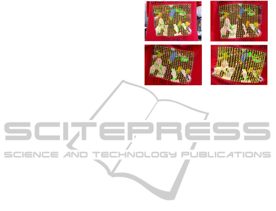
Figure 5: Corresponding points and sampled points. Green
points on the surface denote corresponding points. Yellow
points are the sampled points.
be spread throughout the target region. By using cal-
culated H, each vertices on
¯
V can be transformed to
T . These transformed points are used as target sam-
pling point mesh V
T
. Figure 5 shows corresponding
points and sampled points. Even if the corresponding
points are situated discretely, our method can obtain
sampled points on the target surface point cloud T .
5.2.2 Normalization and Stretching Mesh
Once we get mesh V
T
from the sampled point cloud
obtained in Section 5.2.1, we need to transform it to
the same coordinate system of
¯
V and P
k
. We used the
same rigid transformation matrix M as described in
Hayashi’s paper (Hayashi et al., 2012). M transforms
data in world coordinate system V
T
to normalized co-
ordinate system which is the same as
¯
V and P
k
.
By using M transformation, V
T
is transformed to
normalized mesh V
′
. We can use V
′
as approximation
of V.
At last,
¯
V is stretched so that coordinates of
¯
V
and V
′
become similar to each other. In other word,
each vertices of
¯
V are transformed based on coordi-
nate points. After that, by using these two meshes,
we can calculate each principal component score ω
k
from Eq. 1.
5.2.3 Principal Component Scores Computation
Thus, we can adapt Eq. 1 and Eq. 2 to:
ω
k
= (V
′
−
¯
V
′
) · P
k
. (5)
V =
¯
V
′
+
N
c
∑
k=1
ω
k
P
k
. (6)
This means that each ω
k
that is calculated in the Eq. 5
is compatible to
¯
V
′
. Then we get the mesh V corre-
sponding to T .
VISAPP2013-InternationalConferenceonComputerVisionTheoryandApplications
16
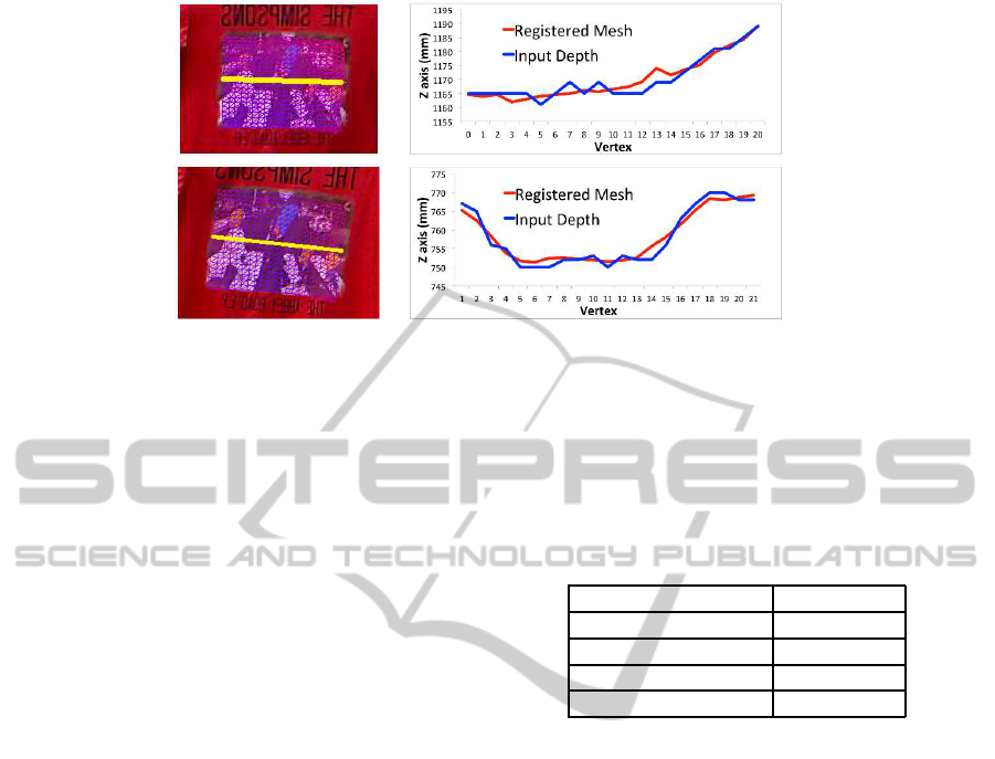
generated mesh comparison with input depth data
Figure 6: Generated mesh and its comparison with depth data from RGB-D camera. The yellow line of left images denotes
the vertices which we used for comparison.
5.2.4 Mesh Projection
The last stage is to transform it to the world coordinate
system. Because we already know transformation M
from the world coordinate system to the normalized
coordinate system, we can transform V by using M
−1
.
For the rendering, we define the texture coordi-
nates for each vertex of a surface mesh. Therefore,
the virtual texture is overlaid on the target surface ob-
tained by M
−1
V.
6 EXPERIMENTAL RESULTS
In this section, we make experiments to confirm the
effectiveness of our method. All the experiments have
been done on a system equipped with a Intel Core
i7-3930K 3.20GHz CPU, NVIDIA GeForece GTX
580 GPU, and 16.0 GB RAM. We use the RGB-D
camera Microsoft Kinect with an image resolution of
640 × 480 pixels and a frame rate of 30 fps. This
RGB-D camera can capture depth component directly
by using infrared in real-time. The target surface is a
region of a T-shirt with texture. For the resolution of
the rectangular mesh, we set both M and N to 21 ver-
tices.
We evaluated generated meshes by comparing
depth (z) value between generated mesh and captured
from RGB-D camera. The results are shown in Fig-
ure 6.Yellow lines on generated mesh denote 20 ver-
tices which we sampled for this evaluation. As Fig-
ure 6 shows, the registered mesh is deformed follow-
ing input depth data. In spite of noisy depth data, our
method can generate similar and smooth mesh.
We calculated the processing time because our
method is supposed to be used for a real-time vir-
tual fitting application. The result of the average pro-
cessing time for 100 frames is shown in Table 2. As
a whole, the average processing speed was over 20
frames per second.
Table 2: Processing time.
Task Time(msec)
Capturing 11
Key Point Detection 22
Mesh Registration 7
Image Rendering 4
Finally, Figure 7 shows visualization results of the
texture overlay onto the non-rigid target surface of 2
kinds of T-shirt. Users can move freely in front of
the camera and perform elastic deformations with the
cloth, including stretching and bending it. Rotation is
possible as long as the texture on the shirt stays visi-
ble. Left two columns of Figure 7 demonstrate results
using T-shirt with rich texture. Right two columns
show results with relatively sparse texture. Even if
the T-shirt does not have special color or markers, our
method can deform mesh to fit the surface according
to the data obtained by RGB-D camera.
7 CONCLUSIONS AND FUTURE
WORKS
In this paper, we presented a non-rigid surface track-
ing methodthat registers 3D deformable mesh for tex-
ture overlay. Our method has several advantages
over the aforementioned previous works. Firstly, our
method does not require makers or special color on
the target surface. Additionally, registering a de-
formed mesh is possible with as few as 7 correspon-
dences. This means that our method is available for
Non-rigidSurfaceTrackingforVirtualFittingSystem
17
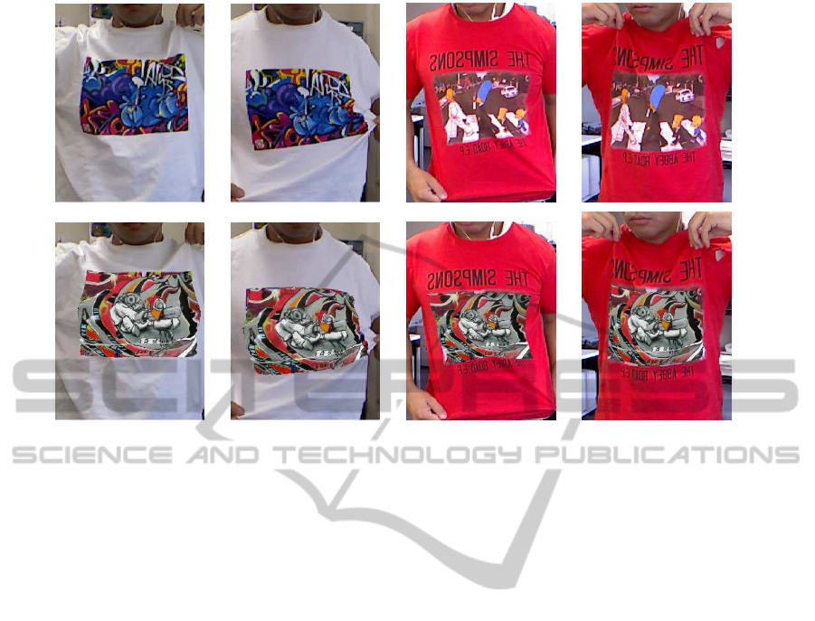
Figure 7: Texture overlaying result. Upper images are input RGB images. Lower images are output images.
relatively poor texture. Secondly, by using low di-
mension deformable model from PCA, our method
obtains a real-time processing.
As a future work, we will improve the method
to detect key points from template and input image.
The accuracy of registered mesh depends on the po-
sitions of key points. If most of the key points are
concentrated to a particular region, then the accuracy
of the generated mesh becomes lower when it is far
from those regions. Therefore we need to improve
the key point detection methodto make detecting the
key points from wider region possible.
In addition, we will take the light source informa-
tion into consideration in texturing part for more nat-
ural visualization.
REFERENCES
Bay, H., Tuytelaars, T., and Van Gool, L. (2006). Surf:
Speeded up robust features. Computer Vision–ECCV
2006, pages 404–417.
Chum, O., Matas, J., and Kittler, J. (2003). Locally opti-
mized ransac. Pattern Recognition, pages 236–243.
Hayashi, T., de Sorbier, F., and Saito, H. (2012). Texture
overlay onto non-rigid surface using commodity depth
camera. In VISAPP.
Hilsmann, A. and Eisert, P. (2009). Tracking and retex-
turing cloth for real-time virtual clothing applications.
In Proceedings of the 4th International Conference
on Computer Vision/Computer Graphics Collabora-
tionTechniques, pages 94–105. Springer-Verlag.
Lowe, D. (1999). Object recognition from local scale-
invariant features. In Computer Vision, 1999. The Pro-
ceedings of the Seventh IEEE International Confer-
ence on, volume 2, pages 1150–1157. Ieee.
Pilet, J., Lepetit, V., and Fua, P. (2007). Fast Non-Rigid Sur-
face Detection, Registration and Realistic Augmenta-
tion. IJCV, 76(2):109–122.
Salzmann, M. and Fua, P. (2011). Linear local models
for monocular reconstruction of deformable surfaces.
PAMI, 33(5):931–44.
Salzmann, M., Pilet, J., Ilic, S., and Fua, P. (2007). Surface
deformation models for nonrigid 3D shape recovery.
PAMI, 29(8):1481–7.
Shen, S., Shi, W., and Liu, Y. (2010). Monocular 3-D track-
ing of inextensible deformable surfaces under L(2) -
norm. image processing, 19(2):512–21.
Yoshida, T., Saito, H., Shimizu, M., and Taguchi, A. (2013).
Stable keypoint recognition using viewpoint genera-
tive learning. In VISAPP.
VISAPP2013-InternationalConferenceonComputerVisionTheoryandApplications
18
