
Direct Depth Recovery from Motion Blur Caused by Random Camera
Rotations Imitating Fixational Eye Movements
Norio Tagawa, Shoei Koizumi and Kan Okubo
Graduate School of System Design, Tokyo Metropolitan University, Hino-shi, Tokyo, Japan
Keywords:
Shape from Motion Blur, Random Camera Rotation, Fixational Eye Movement, Integral Formed Method.
Abstract:
It has been reported that small involuntary vibrations of a human eyeball for fixation called ”fixational eye
movements” play a role of image analysis, for example contrast enhancement and edge detection. This mech-
anism can be interpreted as an instance of stochastic resonance, which is inspired by biology, more specifically
by neuron dynamics. A depth recovery method has been proposed, which uses many successive image pairs
generated by random camera rotations imitating fixational eye movements. This method, however, is not
adequate for images having fine texture details because of an aliasing problem. To overcome this problem,
we propose a new integral formed method for recovering depth, which uses motion blur caused by the same
camera motions, i.e. many random small camera rotations. As an algorithm, we examine a method directly
recovering depth without computing a blur function. To confirm the feasibility of our scheme, we perform
simulations using artificial images.
1 INTRODUCTION
Camera vibration noise is a serious concern for
a hand-held camera and for many vision systems
mounted on mobile platforms such as planes, cars
or mobile robots, and of course for biological vi-
sion systems. The computer vision researchers tra-
ditionally considered the camera vibration as a mere
nuisance and developed various mechanical stabiliza-
tions (Oliver and Quegan, 1998) and filtering tech-
niques (Jazwinski, 1970) to eliminate the jittering
caused by the vibration.
In contrast, the Dynamic Retina (DR)
(Propokopowicz and Cooper, 1995) and the Resonant
Retina (RR) (Hongler et al., 2003), new devices
that take advantage of vibrating noise generated
by mobile platforms, were proposed for contrast
enhancement and edge detection respectively. The
mechanism of those devices can be interpreted as
an instance of stochastic resonance (SR) (Hongler
et al., 2003). SR can be viewed as a noise induced
enhancement of the response of a nonlinear system
to a weak input signal, for example bistable devices
(Gammaitoni et al., 1998) and threshold detectors
(Greenwood et al., 1999), and naturally appears in
many neural dynamics processes (Stemmler, 1996).
As an example of camera vibration noise, we fo-
cus on the small vibrations of a human eyeball, which
occur when we gaze at an object and are called “fix-
ational eye movements.” It has been reported that the
vibrations may work not only as an intrinsic function
to preserve photosensitivity but also as an assistance
in image analysis, which can be considered as a re-
alization of a biological SR phenomenon (Martinez-
Conde et al., 2004). Although DR and RR offer mas-
sive parallelism and simplicity, the depth recovery
method proposed by our group through random cam-
era rotations (Tagawa, 2010) hints more potential of
fixational eye movements, i.e. depth perception po-
tential.
The method (Tagawa, 2010) employs a differen-
tial scheme based on the gradient method for “shape
from motion” (Horn and Schunk, 1981), (Simoncelli,
1999), (Bruhn and Weickert, 2005). Fixational eye
movements are classified into three types: microsac-
cade, drift and tremor, shown in Fig. 3. This method
uses the camera rotations imitating tremor, which is
the smallest of the three types, to reduce the linear ap-
proximation error in the gradient method. However, if
a texture in an image is fine relative to an image mo-
tion size, the method suffers from an aliasing prob-
lem, namely a large amount of error occurs in spatio-
temporal differentials of image intensity used in the
gradient method.
In this study, in order to avoid the above men-
tioned aliasing problem, we propose a new scheme
177
Tagawa N., Koizumi S. and Okubo K..
Direct Depth Recovery from Motion Blur Caused by Random Camera Rotations Imitating Fixational Eye Movements.
DOI: 10.5220/0004304001770186
In Proceedings of the International Conference on Computer Vision Theory and Applications (VISAPP-2013), pages 177-186
ISBN: 978-989-8565-48-8
Copyright
c
2013 SCITEPRESS (Science and Technology Publications, Lda.)

based on an integral form using the same camera ro-
tations adopted by the method (Tagawa, 2010). Small
random camera rotations during exposure can gener-
ate two-dimensional motion-blur in images. The de-
gree of the blur is a function of a pixel position due to
a perspective projection assumed in this study, and it
also depends on the depth value corresponding to the
each pixel. Therefore, the depth map can be recovered
by analyzing the motion-blur.
Several depth recovery methods using motion-
blur have been already proposed, but those use the
blur caused by definite and simple camera motions.
For example, blur by a translational camera mo-
tion is used in Sorel and Flusser (Sorel and Flusser,
2008), and blur by an unconstrained camera motion
composed of translation and rotation is assumed in
Paramanand and Rajagopalan (Paramanand and Ra-
jagopalan, 2012). The depth recovery performance of
those methods may depend on a direction of a tex-
ture in images, i.e., if the texture has a strip pattern
and its direction is parallel to the motion direction in
the image, there is little blur and accurate depth re-
covery is difficult. As against those camera motions,
random camera rotations used in this study is effec-
tive for arbitrary textures. Although only to solve this
problem we can use also complicated but determinis-
tic motions, random camera rotations are easy to im-
plement in an actual system, since there is no need to
control a camera with precision.
The proposed algorithm uses a motion-blurredim-
age and a reference unblurred image. Especially in
this study, from the point view of optimization for
computation, we directly estimate a depth map with-
out computing a space-variant point spread function.
It is expected that the performance of the proposed
scheme depends on the degree of motion blur. For the
same point spread function, i.e. the fixed deviation
of the random camera rotations, fine texture is advan-
tageous for observing the accurate blur. To confirm
this property, we carry out simulations using artificial
images.
2 PRINCIPLE OF DEPTH FROM
MOTION-BLUR
2.1 Camera Motions Imitating Tremor
We use a perspectiveprojection system as our camera-
imaging model. A camera is fixed with an (X,Y,Z)
coordinate system; a lens center corresponding to a
viewpoint is at origin O and an optical axis is along
the Z-axis. By taking a focal length as a unit of ge-
microsaccade
drift
tremor
Figure 1: Illustration of fixational eye movements consist
of microsaccade, drift and tremor.
ometrical representation, a projection plane, i.e. an
image plane Z = 1 can be used without any loss
of generality. A space point (X,Y,Z)
⊤
on an ob-
ject is projected to an image point ~x ≡ (x,y,1)
⊤
=
(X/Z,Y/Z,1)
⊤
.
We briefly explain the motion model imitating
tremor component of fixational eye movements pro-
posed in our previous study (Tagawa, 2010). On the
analogy of a human eyeball, we can set a camera’s ro-
tation center at the back of a lens center with Z
0
along
an optical axis, and we assume that there is no explicit
translational motions of a camera. This rotation can
also be represented using the coordinate origin as its
rotation center with the same components of the rota-
tional vector~r = (r
X
,r
Y
,r
Z
)
⊤
. On the other hand, this
difference between the origin and the rotation center
causes a translational vector~u = (u
X
,u
Y
,u
Z
)
⊤
implic-
itly, and is formulated as follows:
u
X
u
Y
u
Z
=
r
X
r
Y
r
Z
×
0
0
Z
0
= Z
0
r
Y
−r
X
0
. (1)
Generally, a translational motion of a camera is
needed to recover depth, and our camera motion
model can cause it implicitly by only rotating a cam-
era. This camera system can be easily controlled be-
cause of no explicit translations. This means that
generally the system is developed and controlled sim-
ply. Additionally with this system, Z
0
can be simply
known beforehand, hence an absolute depth can be
recovered, although a general camera motion enables
us to get only relative depth. The coordinate system
and the camera motion model used in this study are
shown in Fig. 2.
From Eq. 1, it can be known that r
Z
causes no
translations. Therefore, we set r
Z
= 0 and define
~r = (r
X
,r
Y
,0)
⊤
as a rotational vector like an eyeball.
In this study, to simplify the motion model, ~r(t) is
treated as a stochastic white process, in which t indi-
cates time and ~r(t) is measured absolutely from the
VISAPP2013-InternationalConferenceonComputerVisionTheoryandApplications
178
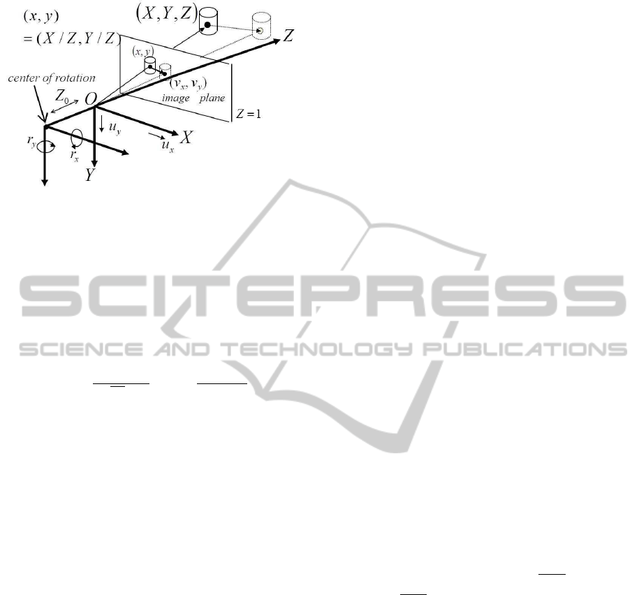
Figure 2: Coordinate system and camera motion model
used in this study.
value at a reference time, i.e.~r(t) is not defined as the
relative value between successive frames here. We ig-
nore the temporal correlation of tremor which forms
drift in actual fact, and we assume that the fluctuation
of~r(t) at each time obeysa two-dimensional Gaussian
distribution with a mean 0 and a variance σ
2
r
, where
σ
2
r
is assumed to be known.
p(~r(t)|σ
2
r
) =
1
(
√
2πσ
r
)
2
exp
−
~r(t)
⊤
~r(t)
2σ
2
r
. (2)
In the above description, we define ~r as a rota-
tional velocity to make a theoretical analysis simple.
In the actual system, we have no choice but to use a
differential rotation, but for small values of the rota-
tion angle, Eq. 1 and the other equations below hold
approximately.
2.2 Motion Blur Associated with Depth
We can measure randomly fluctuating images with
the proposed camera motion model. The previous
method using this camera motion model adopted a
differential formed strategy, i.e. temporal differen-
tials of many image pairs were considered to be mea-
surements, in which an optical flow field was implic-
itly analyzed (Tagawa, 2010). Since this differen-
tial formed method cannot deal with the images hav-
ing fine texture detail because of an aliasing prob-
lem, in this study, we focus on an integral formed
method which analyzes an accumulated image from
small random rotations.
When the exposure time for imaging is sufficient,
the accumulated image, i.e. the motion-blurred im-
age, f
m
(~x) can be modeled as a convolution of an un-
blurred reference image f
0
(~x) with a two-dimensional
point-spread function g
~x
(·) as follows:
f
m
(~x) =
Z
R
g
~x
(~x
′
) f
0
(~x−~x
′
)d~x
′
+ n(~x), (3)
where n(~x) is an imaging noise, R is a local support
region of g
~x
(·) around~x, and
R
g
~x
(~x
′
)d~x
′
= 1 holds. It
is expected that the degree of the motion blur in f
m
(~x)
depends on a local depth value and is reflected in the
degree of the spread of g
~x
(·). In the following, we
examine the relation between g
~x
(·) and a depth value.
Optical flow~v = (v
x
,v
y
,0)
⊤
≡ d~x/dt caused by a
camera motion can be generally formulated using the
inverse depth d(~x) = 1/Z(~x) as follows:
~v = −
I −~x
~
k
⊤
(~r ×~x+ d(~x)~u). (4)
Hence, using Eq. 1, the optical flow caused by our
camera model can be written specially as follows:
~v = −
I −~x
~
k
⊤
(~r ×~x)−Z
0
d(~x)
~r ×
~
k
, (5)
where I indicates a 3 ×3 unit matrix and
~
k is a unit
vector indicating optical axis, i.e.
~
k = (0, 0, 1)
⊤
. This
can be indicated with a component representation as
follows:
v
x
= xyr
X
−(1+ x
2
)r
Y
−Z
0
r
Y
d, (6)
v
y
= (1 + y
2
)r
X
−xyr
Y
+ Z
0
r
X
d. (7)
In addition, from Eq. 2~v can be considered as a two-
dimensional Gaussian random variable with a mean
~
0
and a variance-covariance matrix
~
V [~v] = σ
2
r
n
I −~x
~
k
⊤
I −
~
k~x
⊤
o
2
+2σ
2
r
Z
0
d(~x)
I −~x
~
k
⊤
I −
~
k~x
⊤
+σ
2
r
Z
2
0
d(~x)
2
I −
~
k
~
k
⊤
= σ
2
r
×
"
x
2
y
2
+ (1+ x
2
+ Z
0
d)
2
2xy(1+
x
2
+y
2
2
+ Z
0
d)
2xy(1+
x
2
+y
2
2
+ Z
0
d) x
2
y
2
+ (1+ y
2
+ Z
0
d)
2
#
.
(8)
From these discussion, intensity at each pixel is added
up a lot of neighboring pixel’s intensity and a rela-
tive displacement from such a neighboring pixel per
unit time can be approximately considered as the op-
tical flow defined by Eq. 5. Therefore, it is clear
that g
~x
(·) can be modeled approximately by a two-
dimensional Gaussian distribution having the same
variance-covariance matrix of Eq. 8. Hence, the
motion-blur caused by our camera model depends on
the depth map, and Eq. 3 can be used as an obser-
vation equation including the unknown variable d(~x).
Hereafter, we use the representation g
~x
(·;d) to clarify
that the blur is a function of depth.
DirectDepthRecoveryfromMotionBlurCausedbyRandomCameraRotationsImitatingFixationalEyeMovements
179

3 ALGORITHM DESCRIPTION
With optimality in mind, we examine the direct
method which directly estimate a depth map without
determining g
~x
(·;d), although this strategy generally
requires a numerical search or an iterative update. We
construct two algorithms of a direct method, each of
which employs respectively a local optimization and
a global optimization. In the following, we briefly ex-
plain both algorithms. It should be noted that since the
scheme examined in this study is based on the spatial
blur, high resolution recovery cannot be expected es-
sentially. The proposed algorithms introduced in the
following employ simple computations with no com-
plicated techniques for edge preserved recovery and
so on. If high resolution and high accurate recovery
is needed, for example, the methods based on differ-
ential schemes have to be performed using the results
obtained by the algorithms in this study as an initial
values. At that time, by applying image warping pro-
cessing with the initial depth values, the aliasing prob-
lem concerned in the differential scheme can be ef-
fectively avoided (Simoncelli, 1999), (Tagawa et al.,
2008), (Tagawa and Naganuma, 2009).
A. Local Optimization Algorithm
For stable recovery, we assume that a depth value in
a local region L around each ~x is constant. We can
define the objective function with respect to the depth
corresponding to each pixel based on the minimum
least square criterion.
J
L
(d(~x)) ≡
Z
L
( f
m
(~x−~x”) − f
conv
(~x−~x”))
2
d~x”, (9)
f
conv
(~x) ≡
Z
R
g
~x
(~x
′
;d) f
0
(~x−~x
′
)d~x
′
. (10)
By minimizing this function defined at each ~x re-
spectively, we can recover separately the depth cor-
responding to each pixel. Therefore, a multivariate
optimization is not needed, and we can adopt a one-
dimensional numerical search.
B. Global Optimization Algorithm
By requiring a spatially smooth depth map, we can
define the following functional to be minimized based
on the regularization theory of Poggio et al. (Poggio
et al., 1985).
J
G
(d(~x)) = (1−λ)
Z
( f
m
(~x) − f
conv
(~x))
2
d~x
+λ
Z
(
∂d(~x)
∂x
2
+
∂d(~x)
∂y
2
)
d~x, (11)
where λ is a weight for adjusting the degree of the
smoothness constraint requirement for a depth map,
and the integration in Eq. 11 is carried out in a whole
image. From the variational principle, the Euler-
Lagrange equation for finding the solution of d(~x) is
derived using ∇
2
≡ ∂
2
/∂x
2
+ ∂
2
/∂y
2
as follows:
∇
2
d = −
1−λ
λ
( f
m
− f
conv
)
∂f
conv
∂d
. (12)
For discrete computation, we can approximate the
smoothness constraint in Eq. 11 using (i, j) as a de-
scription of an image position.
∂d(~x)
∂x
2
+
∂d(~x)
∂y
2
≈
1
5
(d
i+1, j
−d
i, j
)
2
+ (d
i, j+1
−d
i, j
)
2
+
1
20
(d
i+1, j−1
−d
i, j
)
2
+ (d
i+1, j+1
−d
i, j
)
2
.(13)
Using Eq. 13 and the discrete representation of
Eq. 12, we can minimize Eq. 11 by the following iter-
ative formulation with an iteration number n.
d
(n+1)
i, j
=
¯
d
(n)
i, j
+
1−λ
λ
f
m,i, j
− f
conv
(d
(n)
i, j
)
∂f
conv
(d
(n)
i, j
)
∂d
,
(14)
¯
d
(n)
i, j
=
1
5
d
(n)
i+1, j
+ d
(n)
i, j+1
+ d
(n)
i−1, j
+ d
(n)
i, j−1
+
1
20
d
(n)
i+1, j+1
+ d
(n)
i+1, j−1
+ d
(n)
i−1, j−1
+ d
(n)
i−1, j+1
.
(15)
4 NUMERICAL EVALUATIONS
The proposed algorithms suppose the definition of the
motion-blurred image in Eq. 3, and this realization
hardly depends on the imaging system and its con-
trol. Namely, to observe the ideal motion-blur, we
have to take sufficient exposure time for imaging, and
during the exposure time camera motion has to be
suitably controlled with small and random properties.
Now, we are developing a real imaging system, and
will confirm the validity of Eq. 3 immediately. In
this study, we examine the performance of the pro-
posed algorithms with respect to the relation between
the image motion size and the fineness of the texture
using artificial data.
We artificially obtain motion-blurred images by
digital signal processing. Firstly, we generate a huge
number of images by a computer graphics technique
using a true depth map and randomly sampling~r ac-
cording to the Gaussian distribution in Eq. 2. An arti-
ficial motion-blurredimage can be made by averaging
VISAPP2013-InternationalConferenceonComputerVisionTheoryandApplications
180
(a)
0
10
20
30
40
50
60
70
0
10
20
30
40
50
60
70
0.08
0.1
0.12
0.14
0.16
0.18
0.2
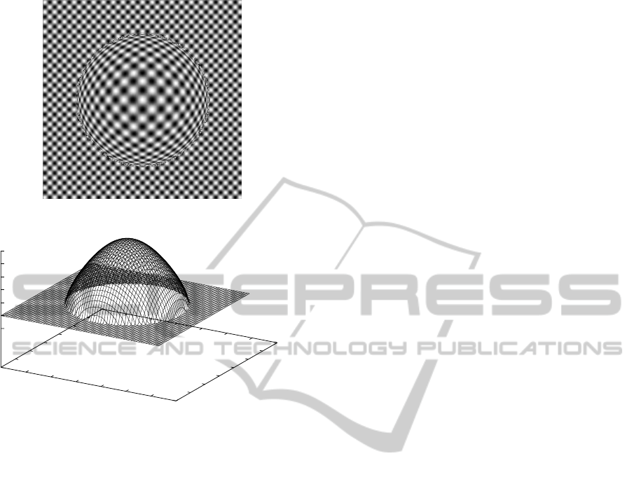
(b)
Figure 3: Example of the artificial data used in the experi-
ments: (a) original image; (b) true inverse depth map used
for generating the blurred image.
these images. In this study, the input motion-blurred
image is obtained by averaging 10,000 images to im-
itatie analog motion blur. Figure 3 shows an example
of a reference image and a true inverse depth map.
The image size used in the simulations is 256 ×256
pixels, which corresponds to −0.5 ≤ x,y ≤ 0.5 mea-
sured using the focal length as a unit. In Fig. 3(b), the
vertical axis indicates the inverse depth d(~x) using the
focal length as a unit, and the horizontal axes in it in-
dicate a pixel position in the image plane, which is
marked every four pixels.
The local optimization algorithm (LOA) takes
high computational cost at each pixel, and the global
optimization algorithm (GOA) converges slowly.
Hence, we evaluated a hybrid algorithm, in which the
LOA is used sparsely in the image plane to obtain
the initial values for the GOA. On the other hand, the
plane indicating the background in Fig. 3(b) is used as
the initial values for the LOA. Since the LOA is used
for rough estimate, we used a block with 41×41 pix-
els as L in Eq. 9 without any special consideration and
apply the LOA once to each block. On the other hand,
we adaptively determined the size of R in Eq. 10 ac-
cording to the value of the depth updated in the opti-
mization process. Therefore, R took the different size
at each position in the image. We supposed a square
region for R , the side length of which was ten times
as large as the larger of the two deviations of g
~x
(·;d),
i.e. x-deviation and y-deviation, which can be evalu-
ated using Eq. 8.
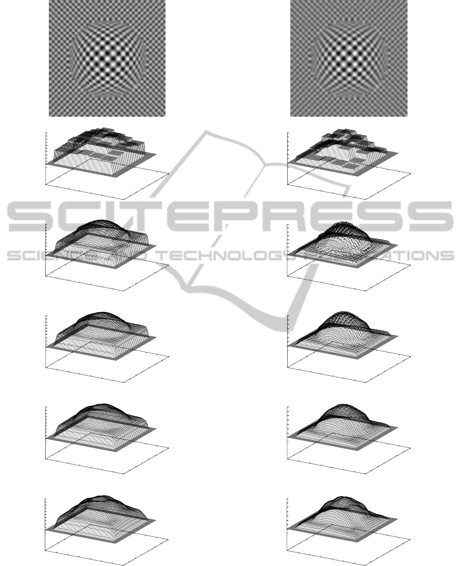
We performed simulations with varying the size
of camera rotation σ
r
. The recovered inverse depth
maps are shown in Figs. 4-6 with various values of λ
used in the GOA. The relation between the root mean
square error (RMSE) of the recovered depth map and
the value of λ is also shown in Fig. 7. From Fig. 4,
it can be easily known that small camera rotations are
inadequate for depth recovery, since the motion blur
in the image position is hard to be measured accu-
rately. From Fig. 7(a), since the measured informa-
tion is poor by the small rotations, the smoothness
constraint indicated by λ is strongly needed to reduce
the RMSE of the recovered depth map. On the con-
trary, the large rotations make the point-spread func-
tion extensivecompared with a spatial variation of the
target shape, and hence the Gaussian function with
the variance-covariance matrix in Eq. 8 is improper
and the motion blur recognized by this model be-
comes smoother than the true blur in the image, which
causes depth recovery error. This can be seen from the
RMSE values in Fig. 7(c). We can confirmed from
Fig. 7(c) also that since the smoothness of the recog-
nized motion blur tends to recover a smooth depth,
the smoothness constraint in Eq. 11 is obstructive for
low RMSE. Figure 8 shows the result with extremely
large rotations of σ
r
= 0.016. Such the rotations are
too large for the texture of the images used in this
evaluation, and it was confirmed that the RMSE is al-
most independent of the value of λ.
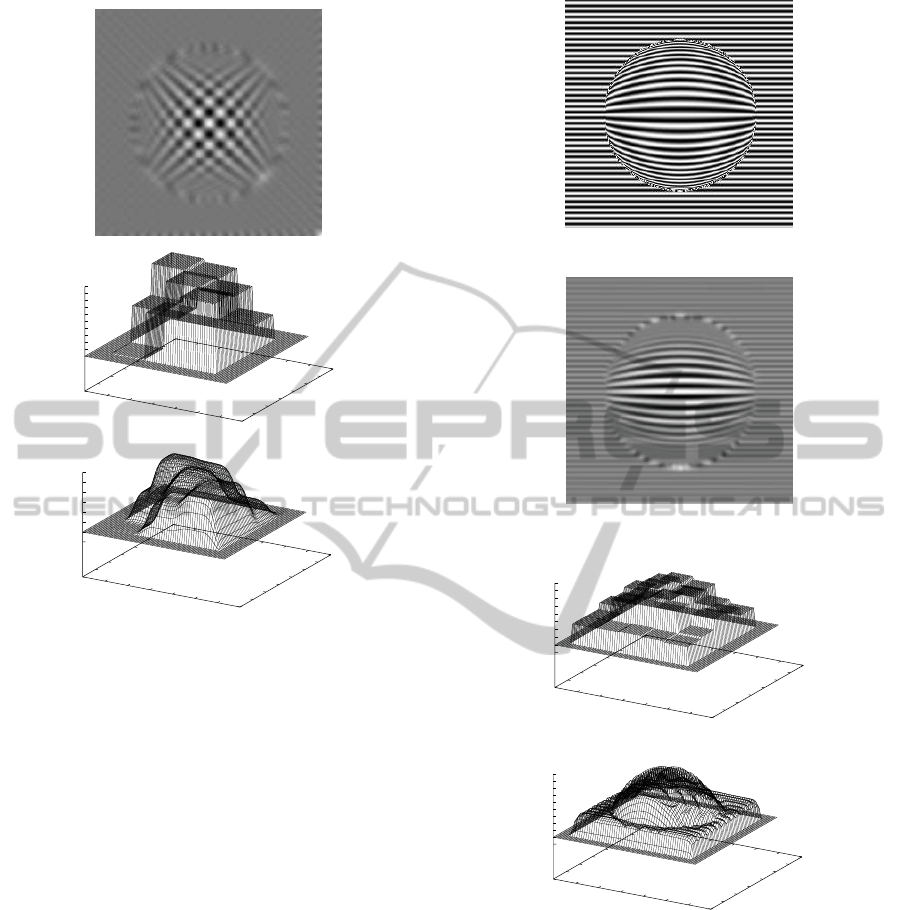
Additionally, we tried to recover a depth from
images having a strip line pattern, which is insuf-
ficient for the method using one-directional motion
blur. Figure 9 shows the original image, the im-
ages blurred with σ
r
= 0.08 and the recovered inverse
depth map with λ = 0.2, the RMSE of which is mini-
mum among various values of λ. From this result, we
confirmed that our integral formed method is suitable
also for such a line pattern image. The case when σ
r
is less than about 0.004, the proposed method can not
obtain good results for the texture patterns used in this
study, because the image motions are too small for the
texture pattern and hence there are little blur. For such
the case, we can use our differential method (Tagawa,
2010) instead.
DirectDepthRecoveryfromMotionBlurCausedbyRandomCameraRotationsImitatingFixationalEyeMovements
181
(a)
(b)
0
10
20
30
40
50
60
70
0
10
20
30
40
50
60
70
0.08
0.1
0.12
0.14
0.16
0.18
0.2
0.22
0.24
0.26
0.28
0.3
(c)
0
10
20
30
40
50
60
70
0
10
20
30
40
50
60
70
0.08
0.1
0.12
0.14
0.16
0.18
0.2
0.22
0.24
0.26
0.28
0.3
(d)
0
10
20
30
40
50
60
70
0
10
20
30
40
50
60
70
0.08
0.1
0.12
0.14
0.16
0.18
0.2
0.22
0.24
0.26
0.28
0.3
(e)
0
10
20
30
40
50
60
70
0
10
20
30
40
50
60
70
0.08
0.1
0.12
0.14
0.16
0.18
0.2
0.22
0.24
0.26
0.28
0.3
(f)
0
10
20
30
40
50
60
70
0
10
20
30
40
50
60
70
0.08
0.1
0.12
0.14
0.16
0.18
0.2
0.22
0.24
0.26
0.28
0.3
Figure 4: Example of motion-blurred image and recovered
inverse depth maps with σ
r
= 0.006: (a) motion-blurred im-
age; (b) local optimization; (c) λ = 0.2; (d) λ = 0.4; (e)
λ = 0.6; (f) λ = 0.8.
(a)
(b)
0
10
20
30
40
50
60
70
0
10
20
30
40
50
60
70
0.08
0.1
0.12
0.14
0.16
0.18
0.2
0.22
0.24
(c)
0
10
20
30
40
50
60
70
0
10
20
30
40
50
60
70
0.08
0.1
0.12
0.14
0.16
0.18
0.2
0.22
0.24
0.26
(d)
0
10
20
30
40
50
60
70
0
10
20
30
40
50
60
70
0.08
0.1
0.12
0.14
0.16
0.18
0.2
0.22
0.24
(e)
0
10
20
30
40
50
60
70
0
10
20
30
40
50
60
70
0.08
0.1
0.12
0.14
0.16
0.18
0.2
0.22
0.24
(f)
0
10
20
30
40
50
60
70
0
10
20
30
40
50
60
70
0.08
0.1
0.12
0.14
0.16
0.18
0.2
0.22
0.24
Figure 5: Example of motion-blurred image and recovered
inverse depth maps with σ
r
= 0.008: (a) motion-blurred im-
age; (b) local optimization; (c) λ = 0.2; (d) λ = 0.4; (e)
λ = 0.6; (f) λ = 0.8.
VISAPP2013-InternationalConferenceonComputerVisionTheoryandApplications
182
(a)
(b)
0
10
20
30
40
50
60
70
0
10
20
30
40
50
60
70
0.08
0.1
0.12
0.14
0.16
0.18
0.2
0.22
0.24
(c)
0
10
20
30
40
50
60
70
0
10
20
30
40
50
60
70
0.08
0.1
0.12
0.14
0.16
0.18
0.2
0.22
0.24
(d)
0
10
20
30
40
50
60
70
0
10
20
30
40
50
60
70
0.08
0.1
0.12
0.14
0.16
0.18
0.2
0.22
0.24
(e)
0
10
20
30
40
50
60
70
0
10
20
30
40
50
60
70
0.08
0.1
0.12
0.14
0.16
0.18
0.2
0.22
0.24
(f)
0
10
20
30
40
50
60
70
0
10
20
30
40
50
60
70
0.08
0.1
0.12
0.14
0.16
0.18
0.2
0.22
0.24
Figure 6: Example of motion-blurred image and recovered
inverse depth maps with σ
r
= 0.01: (a) motion-blurred im-
age; (b) local optimization; (c) λ = 0.2; (d) λ = 0.4; (e)
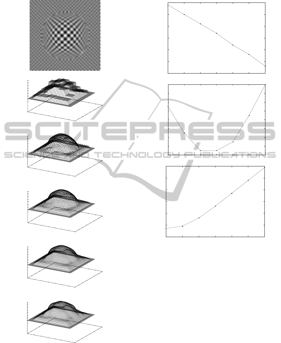
λ = 0.6; (f) λ = 0.8.
(a)
2.6
2.605
2.61
2.615
2.62
2.625
2.63
0.2 0.3 0.4 0.5 0.6 0.7 0.8
RMSE of recovered depth
Lambda
(b)
1.11
1.112
1.114
1.116
1.118
1.12
1.122
1.124
1.126
0.2 0.3 0.4 0.5 0.6 0.7 0.8
RMSE of recovered depth
Lambda
(c)
1.19
1.2
1.21
1.22
1.23
1.24
1.25
0.2 0.3 0.4 0.5 0.6 0.7 0.8
RMSE of recovered depth
Lambda
Figure 7: Relation between RMSE of recovered depth and
lambda: (a) σ
r
= 0.06; (b) σ
r
= 0.08; (c) σ
r
= 0.1.
5 DISCUSSIONS
5.1 Parameter Determination
We understand that the region L in Eq. 9 should be
determined according to the desirable resolution of
the recovered depth map while keeping the constraint
that L has to be larger than the deviation of g
~x
(·;d) to
avoid indefiniteness of depth recovery. On the other
hand, for R in Eq. 10, if there is no need to save com-
putation cost, it is best to use a very large value be-
cause of the infinite support of Gaussian function.
In this study, since we use LOA for obtaining the
initial depth for GOA, we uniformly used the square
of 41 ×41 pixels as L shown in Sec. 4. For R , to
DirectDepthRecoveryfromMotionBlurCausedbyRandomCameraRotationsImitatingFixationalEyeMovements
183
(a)
(b)
0
10
20
30
40
50
60
70
0
10
20
30
40
50
60
70
0.1
0.11
0.12
0.13
0.14
0.15
0.16
0.17
0.18
0.19
0.2
(c)
0
10
20
30
40
50
60
70
0
10
20
30
40
50
60
70
0.08
0.1
0.12
0.14
0.16
0.18
0.2
0.22
Figure 8: Example of motion-blurred image and recovered
inverse depth maps with σ
r
= 0.16: (a) motion-blurred im-
age; (b) local optimization; (c) λ = 0.4, which is an example
that of camera rotations are too large compared with a tex-
ture pattern. L in local optimization is 61×61 pixels.
reduce numerical errors, we used the square large
enough to cover the whole support of g
~x
(·;d) con-
cretely explained in Sec. 4. For the true depth values,
the size of R takes the value between 15 ×15 pixels
and 19 ×19 pixels for σ
r
= 0.005. The size of L of
41×41 is large enough with respect to the size of R
as a result. We confirmed that up to σ
r
= 0.012 L
with 14 ×41 is sufficient with respect to the size of
R , but for σ
r
= 0.016, the recovered result by which
is shown in Fig. 8, the size of L had to be expanded
as 61×61 pixels in LOA.
For the setting of λ, in this study we suppose that
the value should be adjusted empirically while check-
ing the validity of the recovered depth. In future, we
will adopt the EM algorithm (Dempster et al., 1977)
(Tagawa et al., 2008), (Tagawa and Naganuma, 2009)
to solve this problem, by which λ can be automati-
cally determined from only the observed data set. In
this framework, by modeling λ as a function of an im-
age position using an MRF model, spatially adaptive
λ is expected to be determined.
(a)
(b)
(c)
0
10
20
30
40
50
60
70
0
10
20
30
40
50
60
70
0.08
0.1
0.12
0.14
0.16
0.18
0.2
0.22
0.24
0.26
(d)
0
10
20
30
40
50
60
70
0
10
20
30
40
50
60
70
0.08
0.1
0.12
0.14
0.16
0.18
0.2
0.22
0.24
0.26
0.28
Figure 9: Results for horizontal strip pattern with σ
r
= 0.08:
(a) original image; (b) motion-blurred image; (c) local opti-
mization; (d) λ = 0.2 (RMSE = 1.870).
5.2 Relation with Depth from Defocus
At first, we refer to the bad influence of the blur
caused by out of focus on our proposed method. In
this study, we adopt a pinhole camera as an ideal one
having no defocusing to simply explain our idea, but
actual cameras can be used generally in our method.
If the camera rotations are not so large, which is as-
sumed in this study from the beginning, the degree
VISAPP2013-InternationalConferenceonComputerVisionTheoryandApplications
184

of the blur caused by defocusing is unchanging be-
fore and after the camera rotations. Our method uses
a reference image and a blurred image for processing,
and both have the same defocusing-blur, hence our
method can cancel automatically the defocusing-blur.
Next, we explain the advantages of our method
over the depth-from-focus method (Nayar and Nak-
agawa, 1994). In the depth-from-focus method, fo-
cus should be varied accurately in several different
ways. However, in our method, a camera has only
to be rotated randomly, i.e. accurate control of a cam-
era is not required. Since, in our future method, the
deviation of the random camera rotations will be es-
timated from the observed images, there will be no
need to know the deviation before processing. An-
other advantage of our motion-blur scheme is that a
lot of still images having no motion-blur, which are
averaged to generate a motion-blur image, can be ob-
served and processed if needed. Depth recoverybased
on either motion-blur or defocusing-blur is fitted for
sufficiently fine textures, hence surfaces with origi-
nally blurred texture cannot be handled. However, if
camera rotations are adopted, we can deal with such a
smooth texture using the differential method (Tagawa,
2010). Hence, we can adaptively recover the depth by
switching the integral method proposed in this study
and the differential method according to the fineness
of the surface texture.
6 CONCLUSIONS
We propose a new method to recover a depth map
using the camera rotations imitating fixational eye
movements, in particular tremor-related movements.
The proposed method can compute a depth map di-
rectly from blurred image. In this study, we approx-
imate the motion-blurred image by averaging a huge
number of images artificially generated by the random
camera rotations, and we are yet to examine the ef-
fectiveness of our method by real image experiments
using an actual imaging system in the future work.
The simulations in this study did not consider lighting
condition and reflection characteristics of an imaging
target. Especially, to examine an influence of spec-
ular reflection components, at first numerical evalua-
tions have to be done throughly, and subsequent ex-
periments are strongly required.
An outline of a depth map can be recovered by
the method in the simulations, but its accuracy may
be insufficient. The proposed method cannot be used
for small image motions relative to a texture pattern.
For this case, the differential formed method (Tagawa,
2010) is effective. On the other hand, from the funda-
mental principle of our method that the image blur is
used for depth recovery, the spatial resolution of the
recovered depth is not so high, no matter how careful
we are on selecting the camera motion size. For this
case, we can use the results from the proposedintegral
method as an initial depth for the method (Tagawa
et al., 2008) (Tagawa and Naganuma, 2009). Hence,
we plan on unifying those methods to deal with var-
ious situations. Especially to combine the differen-
tial method (Tagawa, 2010) and the integral method
in this paper, we have to develop a suitable segmenta-
tion method, which divides observed images into fine
texture regions and rough texture regions, taking into
account the size of camera rotations. Additionally, to
use both of the differential and the integral methods
simultaneously, the motion-blurred image has to be
generated by averaging many captured images with-
out motion blur instead of simply capturing analog
blur image using the suitable exposure time. For the
case, lesser number of the image used for averaging is
desirable for computational costa and real-time opera-
tion, but this requirement cannot realize the ideal mo-
tion blur supposed in this study. Therefore, we have
to improve the integral method in this study to give a
good performance using such the insufficient motion
blur.
REFERENCES
Bruhn, A. and Weickert, J. (2005). Locas/kanade meets
horn/schunk: combining local and global optic flow
methods. Int. J. Comput. Vision, 61(3):211–231.
Dempster, A. P., Laird, N. M., and Rubin, D. B. (1977).
Maximum likelihood from incomplete data. J. Roy.
Statist. Soc. B, 39:1–38.
Gammaitoni, L., Hanggi, P., Jung, P., and Marchesoni, F.
(1998). Stochastic resonance.
Greenwood, P. E., Ward, L. M., and Wefelmeyer, W. (1999).
Statistical analysis of stochastic resonance in a simple
setting. Physical Rev. E, 60:4687–4696.
Hongler, M.-O., de Meneses, Y. L., Beyeler, A., and Jacot,
J. (2003). The resonant retina: exploiting vibration
noise to optimally detect edges in an image. IEEE
Trans. Pattern Anal. Machine Intell., 25(9):1051–
1062.
Horn, B. P. and Schunk, B. (1981). Determining optical
flow. Artif. Intell., 17:185–203.
Jazwinski, A. (1970). Stochastic processes and filtering the-
ory. Academic Press.
Martinez-Conde, S., Macknik, S. L., and Hubel, D. (2004).
The role of fixational eye movements in visual percep-
tion. Nature Reviews, 5:229–240.
Nayar, S. K. and Nakagawa, Y. (1994). Shape from focus.
IEEE Trans. Pattern Anal. Machine Intell., 16(8):824–
831.
DirectDepthRecoveryfromMotionBlurCausedbyRandomCameraRotationsImitatingFixationalEyeMovements
185

Oliver, C. and Quegan, S. (1998). Understanding synthetic
aperture radar images. Artech House, London.
Paramanand, C. and Rajagopalan, A. N. (2012). Depth from
motion and optical blur with unscented kalman filter.
IEEE Trans. Image Processing, 21(5):2798–2811.
Poggio, T., Torre, V., and Koch, C. (1985). Computational
vision and regularization theory. Nature, 317:314–
319.
Propokopowicz, P. and Cooper, P. (1995). The dynamic
retina. Int’l J. Computer Vision., 16:191–204.
Simoncelli, E. P. (1999). Bayesian multi-scale differential
optical flow. In Handbook of Computer Vision and
Applications, pages 397–422. Academic Press.
Sorel, M. and Flusser, J. (2008). Space-variant restoration
of images degraded by camera motion blur. IEEE
Trans. Image Processing, 17(2):105–116.
Stemmler, M. (1996). A single spike suffices: the simplest
form of stochastic resonance in model neuron. Net-
work: Computations in Neural Systems, 61(7):687–
716.
Tagawa, N. (2010). Depth perception model based on fix-
ational eye movements using byesian statistical infer-
ence. In proc. ICPR2010, pages 1662–1665.
Tagawa, N., Kawaguchi, J., Naganuma, S., and Okubo, K.
(2008). Direct 3-d shape recovery from image se-
quence based on multi-scale bayesian network. In
proc. ICPR08, page CD.
Tagawa, N. and Naganuma, S. (2009). Pattern Recognition,
Structure and motion from image sequence based on
multi-scale Bayesian network. In-Tech, Croatia.
VISAPP2013-InternationalConferenceonComputerVisionTheoryandApplications
186
