
Closed-loop Interrogation Techniques for Temperature Measurement
using Fibre Bragg Gratings
Felipe Walter D. Pfrimer, Marcela H. Koyama, Elnatan C. Ferreira and Jos´e A. Siqueira Dias
Department of Electronics and Microelectronics, School of Electrical and Computer Engineering, University of Campinas,
Av. Albert Einstein, 400, Campinas, SP, Brazil
Keywords:
FBG Interrogation Circuit, Closed-loop Measurement Technique, Multi-point Interrogation.
Abstract:
Closed-loop schemes which maintain the amplitude of the reflected light from the FBG sensors at a constant
level are proposed to implement interrogators for FBG temperature sensors. Two systems are presented: a
very low-cost system where a thermoelectric cooler is used to tune a DFB laser, and a more complex multi-
point system with a broadband laser where n tracking FBGs located inside the interrogator are tuned by
n thermoelectric modules. The variation of the laser wavelength with temperature (or the variation of the
tracking FBGs with the temperature) is used to perform the measurements. Since the values of temperature in
these devices are uniquely associated with the sensing FBG reflected wavelength, if the temperature behaviour
of the FBG sensor is known, by measuring the temperature in the laser (or in the tracking FBGs) it is possible
to accurately calculate the temperature in the FBG sensors. A single-point sensor prototype was constructed to
validate the technique and a very high resolution of ±0.08 m
◦
C was measured in a 100
◦
C temperature range.
1 INTRODUCTION
Fiber Bragg Gratings (FBG) optical sensors became
very popular since they are relatively easy to inter-
rogate. Since applying a strain that stretches a FBG
causes a change in its gratings period, the strain re-
sults in a change in wavelength of the light reflected
by the FBG. Thus, to interrogate a FBG, it is neces-
sary to measure the variation of the centre wavelength
of the FBG, usually called the Bragg shifts (Hill and
Meltz, 1997).
However, due to the small dependency of the
Bragg shifts with temperature for a naked FBG, inter-
rogators with very high resolutions wavelength mea-
surement are required. For example, since a typ-
ical naked FBG presents a ∆λ/∆T ≈ 10 pm.
◦
C
−1
(Othonos and Kalli, 1999), the interrogator should
present a 1 pm resolution if a resolution of 0.1
◦
C
is required in the measurement system. Furthermore,
techniques which employ sophisticated optical com-
ponents in the interrogation system are usually very
expensive (Othonos and Kalli, 1999) and cannot be
used in low-cost applications. In this paper we present
two interrogation techniques: a single-point inter-
rogation technique which uses a narrow band DFB
laser and presents very high resolution and low-cost,
and a multi-point closed-loop electronics interroga-
tion technique which employs a broad band laser and
has a very fast interrogation speed.
2 THE PROPOSED TECHNIQUE
2.1 Principle of Operation
The basics of the proposed closed-loop interrogation
technique is shown in the block diagram of Figure 1,
where a closed-loop interrogation system with a DFB
narrow band laser is shown. The FBG sensor is illu-
minated by a DFB laser with wavelength λ
0
through
optical coupler OC
1
. The reflected light by the FBG is
sent to the photodiode D
1
and the photodiode current
is converted to voltage in the transimpedance ampli-
fier A
1
. To show the principle of operation of the sys-
tem it will be assumed that when the laser wavelength
is at the FWHM (Full Width at Half Maximum) of the
FBG, the output voltage of the transimpedance ampli-
fier will be equal to V
0
.
In (Dias et al., 2008), a feedback control of the
operating point of a FBG was proposed, in order to
allow for the interrogation of ac signals around the
operation point. In this paper a similar approach is
used, and a feedback loop is implemented in order to
force the laser’s output wavelength track the changes
35
Walter D. Pfrimer F., H. Koyama M., C. Ferreira E. and A. Siqueira Dias J..
Closed-loop Interrogation Techniques for Temperature Measurement using Fibre Bragg Gratings.
DOI: 10.5220/0004308300350039
In Proceedings of the International Conference on Photonics, Optics and Laser Technology (PHOTOPTICS-2013), pages 35-39
ISBN: 978-989-8565-44-0
Copyright
c
2013 SCITEPRESS (Science and Technology Publications, Lda.)

TEC
V
REF
= V
0
DFB LASER
+
-
FBG
Vo u t
OC
1
+
-
λ
0
V
TEC
R0
D
1
A
1
PID
Controller
TEC
Driver
R0
Vref
Vth
R
TH
Figure 1: Block diagram of the basic closed-loop interroga-
tion technique.
of the FBG (caused by an external strain, in this case a
temperature variation) so that the output voltage of the
transimpedance amplifier will always be at V
0
. This
is done by entering the output of the transimpedance
amplifier and a reference voltage (numerically equal
to V
0
) in a PID controller which output will drive the
thermoelectric cooler (TEC) normally found in DFB
lasers (Cremonezi et al., 2012).
If a characterization of the laser’s wavelength as
a function of the laser’s temperature is performed us-
ing the internal thermistor available in the DFB laser’s
package, by measuring the voltage V
TH
in a volt-
age divider made with the thermistor, it is possible to
know the wavelength of the laser and, consequently,
the temperature of the FBG.
2.2 Multi-Point FBG Sensing with
Narrow Band DFB Lasers
The proposed technique can be used to interrogate
multiple FBGs. However, if the system is illuminated
with a narrow DFB laser and the sensors are chained
in a series configuration, there is a trade-off between
temperature range and number of points possible to
interrogate. Low-cost lasers usually can be tuned over
a 2 nm range when heated/cooled by its internal ther-
moelectric cooler, resulting in a temperature scanning
range of approximately 200
◦
C. This results in a se-
rious limitation because, if, for example, four FBGs
are to be inserted in the same optical fibre, each FBG
will be allowed to have an excursion of only approxi-
mately 50
◦
C or overlapping of the spectra will occur.
If a low excursion range is acceptable, a very sim-
ple and low-cost interrogation can be implemented,
as shown in Figure 2. A single microcontroller con-
trols the whole system, and also implements a digital
PID controller, which is the core of the interrogator.
The system is initialized by forcing the laser to its
minimum temperature, which leads to the minimum
wavelength in the laser’s output. Then an analogue
class AB power amplifier A
2
, controlled by a micro-
controller’s internal DAC, drives the TEC (heating it)
while the output of the transimpedance amplifier V
out
is monitored by an A/D converter also internal to the
microcontroller.
When the value of V
out
reaches 10% of V
0
, (that
is, when the laser wavelength is beginning to enter
the FBG spectrum), the output of the DAC is discon-
nected from the TEC driver and the the output of the
PID controller is fed into the input of the TEC power
driverA
2
. The PID circuit acts and the system reaches
its steady state value, with V
out
= V
0
. The A/D con-
verter checks if the system is stable while another
channel of the A/D converter measures the voltage at
the thermistor V
TH
. Since V
TH
is uniquely related to
the lasers wavelength output, the exact position (and
consequently the temperature) of the FBG can be eas-
ily calculated.
TEC
V
REF
= V
0
DFB LASER
+
-
Vo u t
OC
1
+
-
λ
0
V
TEC
R
0
D
1
A
1
TEC
Driver
R0
Vref
1
Vth
R
TH
FBG
3
FBG
2
FBG
1
microcontroller
A
2
Digital PID
Algorithm
DAC
A/D
Scanning
Algorithm
Figure 2: Block diagram of the DFB laser single-point
closed-loop interrogator.
PHOTOPTICS2013-InternationalConferenceonPhotonics,OpticsandLaserTechnology
36
After the temperature of the first FBG is read, the
PID controller is disconnected from the TEC power
driver and the microcontroller DAC starts to heat the
TEC, in order to the laser reach the next FBG. Again,
when the output of the transimpedance amplifier indi-
cates that the laser wavelength is at the beginning of
the spectrum of next FBG, the same procedure done
with the first FBG is repeated (the DAC is discon-
nected, the PID takes control of the system, etc.). This
is repeated until the last FBG in the chain is measured,
when the system begins to travel backwards (by cool-
ing the laser), in the direction of the first FBG.
The only difference when measuring the FBGs
during the returning path (cooling the laser) is that
now it is necessary to drive the TEC until the laser
crosses the whole FBG spectrum and the condition
V
out
= 0.9V
0
is reached, that is, the laser wavelength
is at the left side of the FBG so that the PID takes
control of the system always at the same point. It is
important to notice that this system is relatively slow,
since the measurements cannot be performed simul-
taneously and the time required to scan four FBGS
(heating/cooling time, PID time necessary to stabilize
the system) can take up to 2 minutes.
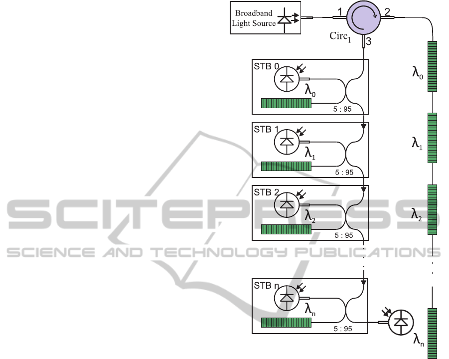
2.3 Multi-Point FBG Sensing with
Broad Band Lasers
Implementing a closed-loop interrogator using a
broad band laser leads to a system which can accept a
large number of sensing FBGs and a extremely very
fast measurement time, typically in the order of a few
microseconds for each FBG. A block diagram of the
interrogation system using a broad band laser is pre-
sented in Figure 3. In this scheme, the number of
optical components is proportional to the number of
FBGs sensing elements, and the final cost of an inter-
rogation system with input for more than 3 FBG tem-
perature sensors is dominated by the cost of the opti-
cal components (tracking FBGs, couplers and photo-
diodes).
The broad band laser illuminates the chain with
n FBGs sensing elements through a optical circula-
tor Circ
1
. The reflected light from the chain of FBG
sensing elements is fed into a series of optical cou-
plers. Each optical coupler let 95% of the incoming
light goes to the next coupler, and 5% of the light
is directed into a small circuit called Signal Tracking
Block (STB
i
. In each STB there is one FBG (called
tracking FBG, which is glued to a Zn substrate), one
photodiode, one thermoelectric cooler, one semicon-
ductor temperature sensor and one microcontroller
with its the electronic circuitry. Although it is not nec-
essary that the tracking FBGs be matched to the sens-
Figure 3: Block diagram of the broad band laser multi-point
closed-loop interrogator.
ing FBGs, it is easier to design the system if the FBGs
in each pair of tracking/sensing FBGS have their cen-
tre λ close. The basic schematic of each STB block is
presented in Figure 4,
The STB electronics circuits drive the TEC while
the microcontroller acquires the output of the tran-
simpedance amplifier, which value is equal to the con-
volution between the sensing and the tracking FBGs.
A PID algorithm executed in the microcontroller con-
trols a DAC and a TEC driver circuit, forcing the
value of this convolution (output voltage of the tran-
simpedance amplifier V
out
) to be equal to a reference
value V
ref
. If the temperature behaviour of the track-
ing FBG was previously characterized, measuring its
temperature it is possible to determine the centre λ of
the tracking FBG. Knowing the centre λ of the track-
ing FBG and remembering that, in the same FBG pro-
file (one has to choose to operate on the left or on the
right side of the FBG profile) the convolution value
is uniquely related to the centre wavelength of sens-
Closed-loopInterrogationTechniquesforTemperatureMeasurementusingFibreBraggGratings
37
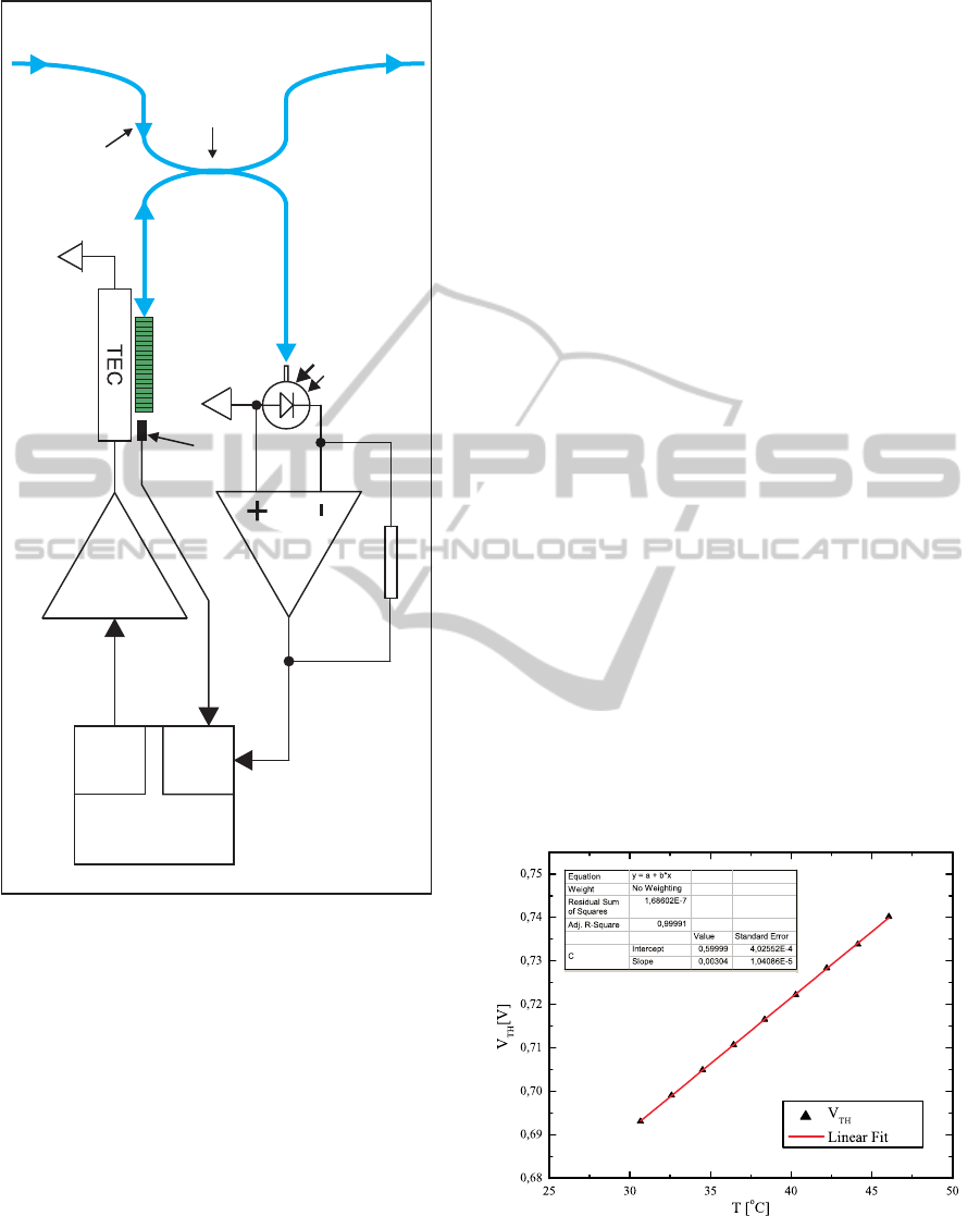
Transimpedance
amplifier
D
1
Tracking FBG
Microcontroller
STB
n
TEC
Driver
From STB
n-1
To STB
n+1
IC temperature
sensor
DAC
ADC
Optical Isolator
2x2
Optical Coupler
95% : 5%
Convolution
R
Figure 4: Schematic of the Signal Tracking Block - STB.
ing FBG, the temperature of the sensing FBG is easily
calculated.
The system may require up to one minute to
have all STBs in steady state, due to the slow heat-
ing/cooling which is used to control the tracking
FBGs. However, once the steady state is reached,
all the signal processing for the stabilization of the n
sensing FBGs is done in parallel, and it requires only
a few microseconds to interrogate each one of the n
channels, since all that has to be done is to convert the
analogue voltage V
out
to digital.
3 EXPERIMENTAL RESULTS
A prototype of a single-point FBG interrogator us-
ing a 1550 nm DFB laser (Eudyna Devices USA,
2004) was implemented to validate the principle of
the closed-loop technique. In the developed prototype
(block diagram shown in Figure 4), an analogue PID
controller was used, and the microcontroller was re-
sponsible only for scanning the system during start-up
and for reading the voltage V
TH
at the thermistor.
The system was tested in the temperature range of
−20
◦
C to 80
◦
C, and the resolution obtained was very
high since, after reaching the steady-state, the output
voltage of the transimpedance amplifier presented a
maximum fluctuation which was less than 10µV, in
an output signal of 2.5 V. The edge of the sensing
FBG profile has a width of approximately 400 pm and
a variation from 0% to 100% of the FBG reflected
light reaching the photodiode causes a voltage varia-
tion equal to 5 V in the output of the transimpedance
amplifier. Therefore, the slope of the FBG profile is
about 40 pm/V. Since a voltage change of 20µV can
be measured, it means that a variation of 800.10
−6
pm can be detected. This result indicates that the de-
veloped closed-loop single point interrogator using a
DFB laser presents a resolution of 0.08m
◦
C for a typ-
ical naked FBG with ∆λ/∆T = 10 pm.
◦
C
−1
.
A plot of the measured data in the prototype for
the temperature range of 30
◦
C to 47
◦
C is shown in
Figure 5, where it is presented the thermistor voltage
measured as a function of the temperature in the FBG
sensor, acquired with a precision AD590M (Timko,
1976) temperature transducer.
Figure 5: Plot of the thermistor voltage V
TH
as a function
of the temperature measured with an AD590M temperature
transducer.
PHOTOPTICS2013-InternationalConferenceonPhotonics,OpticsandLaserTechnology
38

4 DISCUSSIONS
AND CONCLUSIONS
Three techniques for the implementation of closed-
loop interrogators for FBG temperature sensing appli-
cations were presented. A very low-cost single-point
interrogator can be constructed with only three opti-
cal components, a DFB laser, an optical coupler and a
photodiode. This interrogator has an extremely high
resolution (80 µ
◦
C for a naked FBG sensor) and with
a 2 nm tunable DFB laser it can measure temperatures
over a 200
◦
C range.
The DFB laser technique can also be used in
multi-point temperature measurements, but the sys-
tem presents limitations: the interrogator is slow (up
to two minutes can be necessary to measure FBGs
which are at the extreme points of the temperature
range), and there is a trade-off between the number of
sensing FBGs and the maximum temperature range
that each FBG can measure. Nevertheless, the sys-
tem presents a very high resolution and is extremely
cheap, since the cost of all components necessary to
implement the interrogator is around 300 Euro at the
time of writing.
A multi-point closed-loop interrogator scheme
that uses a broad band laser was also presented. This
technique is extremely fast and each FBG sensing el-
ement can be interrogated in a few microseconds. The
system is modular and can be easily built to oper-
ate with a custom number of channels. Since part
of the optical power is lost in the series of the opti-
cal couplers inside the equipment, it is expected that
the maximum number of channels would be limited
to 30-40. The multi-point closed-loop interrogation
technique is much more expensive than the technique
which uses the DFB laser because each interrogation
channel requires one FBG, one optical coupler and
one photodiode. The electronics circuits, TECs and
IC temperature sensors which are necessary to imple-
ment the interrogator are only a fraction of the cost of
the optical components and, therefore, the cost of the
interrogator is basically given by the optical compo-
nents.
ACKNOWLEDGEMENTS
This project was partially supported by Conselho Na-
cional de Desenvolvimento Cient´ıfico e Tecnol´ogico
- CNPq/Brazil and Coordenac¸˜ao de Aperfeioamento
do Pessoal de N´ıvel Superior - CAPES/Brazil.
REFERENCES
Cremonezi, A., Ferreira, E., Biazon Filho, A., and
Siqueira Dias, J. (2012). A fiber bragg grating rms
current transducer based on the magnetostriction ef-
fect using a terfenol-d toroidal shaped modulator. Sen-
sors Journal, IEEEl, PP(99):1.
Dias, J. S., Leite, R., and Ferreira, E. (2008). Electronic
technique for temperature compensation of fibre bragg
gratings sensors. AEU - International Journal of Elec-
tronics and Communications, 62(1):72–76.
Eudyna Devices USA, I. (2004). 1,550nm DFB DWDM
Direct Modulation Laser FLD5F6CX-E Data Sheet.
Hill, K. O. and Meltz, G. (1997). Fiber bragg grating tech-
nology fundamentals and overview. IEEE J.Lightwave
Tech., 15:1263–1276.
Othonos, A. and Kalli, K. (1999). Fiber Bragg Grat-
ings Fundamentals and applications in Telecommu-
nications and Sensing. Artech House, Norwood, MA
- USA.
Timko, M. P. (1976). A two-terminal ic temperature trans-
ducer. IEEE Journal of Solid-State Circuits, SC-
11(6):784–788.
Closed-loopInterrogationTechniquesforTemperatureMeasurementusingFibreBraggGratings
39
