
UML-based Design and Verification Method
for Developing Dependable Context-aware Systems
Naoyasu Ubayashi and Yasutaka Kamei
Kyushu University, Fukuoka, Japan
Keywords:
Context-aware System, Context-Oriented Programming, Trace Analysis, SMT.
Abstract:
This paper proposes a verification mechanism for designing dependable context-aware systems. In our ap-
proach, a UML-based design model and actual execution trace data are translated into a logical formula. The
validity of a design model, the correspondence between the design and the execution, and the non-functional
properties can be verified automatically. For this checking, we use an SMT solver.
1 INTRODUCTION
Context-awareness plays an important role in devel-
oping flexible and adaptive systems that can change
their behavior according to their context (Kramer and
Magee, 2007). However, it is not easy to design and
implement such a context-aware system, because its
system configuration is dynamically changed. It is
hard to check whether a design model is correctly
implemented and its behavior is faithful to the de-
sign. Runtime verification is one of the promising
approaches for relaxing this problem. It is effective
to log the execution events of a program and check
whether the trace satisfies the properties specified in
the design. However, it is still difficult to check the
validity of a design and the correspondence between
the design and its actual event trace, because context
cannot be treated as a module in the traditional design
methods and programming languages. Context is de-
signed or implemented in an ad-hoc manner in tradi-
tional approaches. As a result, it is difficult to map a
design-level event such as context change to an event
in an execution trace. To deal with this problem, this
paper applies the notion of COP (Context-Oriented
Programming) (R. Hirschfeld and Nierstrasz, 2008)
to a design and verification method for developing
context-aware systems. COP can treat context as
a module and enables programmers to describe the
context-aware behavior elegantly.
This paper provides RV4COP, a runtime verifi-
cation mechanism based on UML4COP (Ubayashi
and Kamei, 2012) in which each context is mod-
eled separately from a base design model represent-
ing only primary system behavior. A system design
model is composed by merging associated contexts.
In RV4COP, a system design model and actual exe-
cution trace data at a certain period of time are trans-
lated into a logical formula. A variety of properties
can be checked automatically. For this checking, we
use an SMT (Satisfiability Modulo Theories) solver
(A. Biere and Walsh, 2009), a tool for deciding the
satisfiability of logical formulas.
This paper is structured as follows. In Section 2,
we introduce COP and UML4COP. In Section 3, we
propose RV4COP. Concluding remarks are provided
in Section 4.
2 COP AND UML4COP
In this section, first, we introduce the overview of
COP. Next, we briefly excerpt UML4COP from our
previous work (Ubayashi and Kamei, 2012).
2.1 COP Overview
COP provides a mechanism for dynamically adapt-
ing the behavior to the new context. There are sev-
eral COP languages such as ContextJ* and JCop
(R. Hirschfeld and Nierstrasz, 2008). Context is
described by layers, a context-aware modularization
mechanism. A layer, which defines a set of related
context-dependent behavioral variations, can be con-
sidered a module. By entering a layer or exiting
from the layer, a program can change its behavior. A
program captures context-dependent behavior by en-
tering a layer. A layer, a kind of crosscutting con-
89
Ubayashi N. and Kamei Y..
UML-based Design and Verification Method for Developing Dependable Context-aware Systems.
DOI: 10.5220/0004310600890094
In Proceedings of the 1st International Conference on Model-Driven Engineering and Software Development (MODELSWARD-2013), pages 89-94
ISBN: 978-989-8565-42-6
Copyright
c
2013 SCITEPRESS (Science and Technology Publications, Lda.)
㼂㼕㼑㼣㻦㻌㻮㼍㼟㼑
㼂㼕㼑㼣㻦㻌㻭㼐㼐㼞㼑㼟㼟㻌㻸㼍㼥㼑㼞
㼂㼕㼑㼣㻦㻌㻱㼙㼜㼘㼛㼥㼙㼑㼚㼠㻌㻸㼍㼥㼑㼞
Address Layersd
: Actor
Person
[Add a string]
"; Address: " + address
toString()
<<layered method>>
toString()
Employer
: Actor
toString()
<<layered method>>
toString()
Employment Layersd
: Actor
Person
Employer
[Add a string]
"; [Employer] " + employer
toString()
<<layered method>>
toString()
toString()
Address Layerpkg
+ <<layered method>> toString() : String
Person
+ <<layered method>> toString() : String
Employer
[Add a string]
"; Address: " + address
Employment Layerpkg
+ <<layered method>> toString() : String
Person
Employer
[Add a string]
"; [Employer] " + employer
Basepkg
+ main() : void
Test
+ toString() : String
- address : String
- name : String
Person
+ toString() : String
- address : String
- name : String
Employer
print name
Basesd
Person
System.out
Test
println(Person)
toString()
print name
Figure 1: An Example Model Described in UML4COP.
cern, can range over several classes and contain par-
tial method definitions implementing behavioral vari-
ations. A set of partial methods belonging to the
same layer represents the context-dependent behav-
ior. There are two kinds of partial methods: plain
method and layered method. The former is a method
whose execution is not affected by layers. The latter
consists of a base method definition, which is exe-
cuted when no active layer provides a corresponding
partial method, and partial method definitions. Partial
methods are activated when a program enters a layer.
In COP, a systems can be constructed by dynamically
composing a set of associated layers.
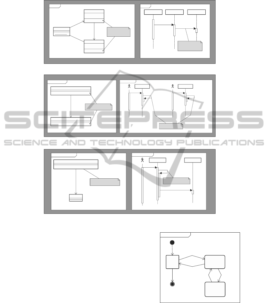
2.2 Design Modeling using UML4COP
UML4COP, a UML-based domain-specific model-
ing language, consists of two kinds of models: view
model and context transition model. The former de-
scribed in class diagrams and sequence diagrams rep-
Context Transitionstm
Base Address
Layer
Employment
Layer
Layer In
Layer Out
Layer Out
Layer In
Figure 2: Context Transition.
resents context. The latter described in state machine
diagrams represents context transitions triggered by
COP-specific events such as layer in and layer out.
Figure 1 and 2 show an example model described
in UML4COP. This example modified from (Con-
textJ*, 2011) is an application that displays a mes-
sage containing a person’s name, address, and em-
MODELSWARD2013-InternationalConferenceonModel-DrivenEngineeringandSoftwareDevelopment
90

[List 1]
01: public class Test {
02: public static void main(String[] args) {
03: final Employer suzuki =
04: new Employer("Suzuki", "Tokyo");
05: final Person tanaka =
06: new Person("Tanaka", "Kyoto", suzuki);
07:
08: with(Layers.Address).eval(new Block() {
09: public void eval() {
10: System.out.println(uchio);
11: }
12: });
13:
14: with(Layers.Address,
15: Layers.Employment).eval(new Block() {
16: public void eval() {
17: System.out.println(uchio);
18: }
19: });
20: }
21: }
[List 2]
01: public class Layers {
02: public static final Layer Address =
03: new Layer("Address");
04: public static final Layer Employment =
05: new Layer("Employment");
06: }
[List 3]
01: public class Person implements IPerson {
02: private String name;
03: private String address;
04: private IEmployer employer;
05:
06: public Person(String newName,
07: String newAddress,
08: IEmployer newEmployer) {
09: this.name = newName;
10: this.address = newAddress;
11: this.employer = newEmployer;
12: }
13:
14: public String toString() {
15: return layers.select().toString();
16: }
17:
18: private LayerDefinitions<IPerson> layers =
19: new LayerDefinitions<IPerson>(new IPerson() {
20: public String toString() {
21: return "Name: " + name;
22: }
23: });
24:
25: { layers.define(Layers.Employment,
26: new IPerson() {
27: public String toString() {
28: return layers.next(this) +
29: "; [Employer] " + employer;
30: }
31: });
32:
33: layers.define(Layers.Address,
34: new IPerson() {
35: public String toString() {
36: return layers.next(this) +
37: "; Address: " + address;
38: }
39: });
40: }
41: }
[List 4]
01: public class Employer implements IEmployer {
02: private String name;
03: private String address;
04:
05: public Employer(String newName,
06: String newAddress) {
07: this.name = newName;
08: this.address = newAddress;
09: }
10:
11: public String toString() {
12: return layers.select().toString();
13: }
14:
15: private LayerDefinitions<IEmployer> layers =
16: new LayerDefinitions<IEmployer>(new IEmployer() {
17: public String toString() {
18: return "Name: " + name;
19: }
20: });
21:
22: { layers.define(Layers.Address,
23: new IEmployer() {
24: public String toString() {
25: return layers.next(this) +
26: "; Address: " + address;
27: }
28: });
29: }
30: }
Figure 3: ContextJ* Program.
ployer. The message content changes according to the
belonging context. In Figure 1, there is one base view
and two layer views: Address and Employment. In
Address layer, a layered method
toString
is called
to display an address. In Employment layer, another
layered method
toString
is called to display an em-
ployer’s profile. In Figure 2, first, this example sys-
tem can enter Address layer. Next, the system can en-
ter Employment layer or exit from Address layer. We
can easily understand system behavior by composing
views according to context transitions. The follow-
ing is the execution result. The same print statement
behaves differently according to the context.
-- In Address Layer
Name: Tanaka; Address: Kyoto
-- In Address Layer and Employment Layer
Name: Tanaka; Address: Kyoto;
[Employer] Name: Suzuki; Address: Tokyo
2.3 Programming in COP Languages
A design model in UML4COP can be easily imple-
mented using COP languages. In List 1 - 4 (Figure
3), we show a ContextJ* program in which two ob-
jects employer (suzuki) (List 1: line 03 - 04, List 4)
and person (tanaka) (List 1: line 05 - 06, List 3)
change their behavior corresponding to the context.
Address and Employment layers are described in List
2. In ContextJ*, an object can enter a contextby using
with
. For example, suzuki and tanaka enter Address
and Employment layers (List 1: line 14 -15) and exit
from the layers (List 1: line 19). The content of each
layer is described in two classes Person (List 3) and
Employer (List 4). For example, Address layer ranges
over Person (List 3: line 33 - 39) and Employer (List
4: line 22 - 28).
LayerDefinitions
(List 3: line
18),
define
(List 3: line 25, 33),
select
(List 3: line
15), and
next
(List 3: line 28, 36) are language con-
structs for layer definitions. The base view in Figure
1 is mapped to the two classes Person and Employer.
The context views are mapped to layer descriptions
ranging over two classes.
3 RUNTIME VERIFICATION
Although UML4COP and COP improve the expres-
siveness for designing and implementing context-
aware systems, it is not necessarily easy to check
whether a program correctly implements its design.
UML-basedDesignandVerificationMethodforDevelopingDependableContext-awareSystems
91

Table 1: Archpoints and ContextJ* Execution Events.
UML4COP Diagram Archpoint (Design Level) ContextJ* Execution Event (Trace Level)
State machine diagram layer in layer with
(Context transition model) layer out layer without
Class diagram layer definition layer instantiation (
new LayerDefinitions
)
(View model) base method definition layer instantiation (
new LayerDefinitions
)
layered method definition layered method definition (
define
method call)
Sequential diagram message send method call
(View model) base method send base method call
layered method send layered method call
message receive method execution
base method receive base method execution
layered method receive layered method execution
To deal with this problem, we propose RV4COP
consisting of three steps: 1) a design model specified
in UML4COP is translated into a logical formula; 2)
execution trace data collected by logging ContextJ*
execution events are converted to a logical formula;
and 3) a variety of checking are performed. Intro-
ducing RV4COP, we can check the correspondence
between design and its execution trace by verifying
the satisfiability of these logical formulas. Our ap-
proach integrates trace-based dynamic analysis with
logic-based formal methods.
3.1 Verification Procedure
Step 1: Translation from a Design Model into a
Logical Formula
A UML4COP model is translated into a logical for-
mula by focusing on the selected COP events called
archpoints, points for representing the essence of ar-
chitectural design. Table 1 shows major archpoints
and related execution events in ContextJ*. Using
archpoints, we can define an abstract design model
representing the essence of context-aware software
architecture. We can verify the crucial aspects of a
design model by ignoring non-essential aspects. The
computing cost and the verification scalability are im-
proved, because the length of a logical formula is
shorten.
In RV4COP, design is defined as a set of arch-
points A = {a
1
, ..., a
n
} and a set of constraints among
them. A design model is regarded correct if the logi-
cal formula below is satisfied. An archcond
i
is a log-
ical expression for specifying a property that should
be satisfied among a set of related archpoints.
DESIGN = archcond
1
∧ ... ∧ archcond
m
(1)
The example design model is translated into List 5
(Figure 4). The
sequence
is a predicate that is satis-
fied when the order of archpoint occurrence is correct.
By defining a set of predicates such as
iteration
and
branch
, we can describe a variety of architectural
properties. The system behavior at a certain period of
time can be composed by merging associated logical
formulas in List 5. For example, the formula
Composition Base Address Employment
in List 6 is generated by merging the four formulas
in List 5 (the same archpoint occurrence is merged).
Taking into account the context transitions, archpoints
such as layer in and layer out are added to List 6.
Step 2: Translation from Trace Data into a Logical
Formula
In RV4COP, trace data can be expressed as a set of
ContextJ* execution events E = {e
1
, ..., e
n
′
} and a set
of constraints among them. A trace is consistent if
the formula below is satisfied. A tracecond
i
is a log-
ical expression for specifying a property that should
be satisfied among a set of execution events.
TRACE = tracecond
1
∧ ... ∧tracecond
m
′
(2)
The execution trace data are translated into a log-
ical formula shown in List 7 (Figure 4).
Step 3: Verification
We can check a variety of design properties: 1) trace-
ability between design and its trace, 2) design con-
sistency by checking DESIGN, and 3) trace valid-
ity by checking TRACE. As an example, we show
how to generate a logical formula for checking 1). In
RV4COP, a refinement mapping from a design model
to its event trace can be defined as a mapping func-
tion
refine
. Using
refine
function, RV4COP can
be applied to a variety of COP languages. In case of
ContextJ*, this mapping can be defined below.
refine( Person_toString_send_@Address ) =
Person_toString_call_layer_@Address
refine( Person_toString_receive_@Address ) =
Person_toString_execution_layer_@Address
refine( Layer_in_@Address ) = Layer_with_@Address
refine( Layer_out ) = Layer_without
Program behavior conforms to its design if the fol-
lowing is satisfied.
refine(DESIGN)∧ TRACE (3)
In the example, this formula is not satisfied. The
sequence
predicate in refine(DESIGN) is false, be-
cause the order of the layered method invocations in
TRACE (List 7) is not correct. A ContextJ* imple-
mentation shown in List 1 - 4 does not conform to
its design. When tanaka (person) enters the Address
and Employment layers, the layered method toString
(Address layer) is invoked after the layered method
MODELSWARD2013-InternationalConferenceonModel-DrivenEngineeringandSoftwareDevelopment
92

[List 5]
View_Base :=
sequence(
Test_println_message_send,
System_out_println_receive,
System_out_toString_send,
Person_toString_receive)
View_Address_Layer_Person :=
sequence(
Person_toString_receive,
Person_toString_send_@Address,
Person_toString_receive_@Address)
View_Address_Layer_Employer :=
sequence(
Employer_toString_receive,
Employer_toString_send_@Address,
Employer_toString_receive_@Address)
View_Employment_Layer :=
sequence(
Person_toString_receive,
Person_toString_send_@Employment,
Person_toString_receive_@Employment,
Person_toString_send,
Employer_toString_receive)
[List 6]
; Merge Base and Address Layer Views
; (num of archpoints is 8)
Composition_Base_Address :=
sequence(
Layer_in_@Address,
Test_println_message_send,
System_out_println_receive,
System_out_toString_send,
Person_toString_receive,
Person_toString_send_@Address,
Person_toString_receive_@Address,
Layer_out)
; Merge Base, Address, and Employment
; Layer Views
; (num of archpoints is 15)
Composition_Base_Address_Employment :=
sequence(
Layer_in_@Address,
Layer_in_@Employment,
Test_println_message_send,
System_out_println_receive,
System_out_toString_send,
Person_toString_receive,
Person_toString_send_@Address,
Person_toString_receive_@Address,
Person_toString_send_@Employment,
Person_toString_receive_@Employment,
Person_toString_send,
Employer_toString_receive,
Employer_toString_send_@Address,
Employer_toString_receive_@Address,
Layer_out)
[List 7]
; num of ContextJ* execution events is 29
Trace :=
sequence(
Layer_with_@Address,
Test_println_message_call,
System_out_println_execution,
System_out_toString_call,
Person_toString_execution,
Person_toString_call_layer_@Address,
Person_toString_execution_layer_@Address,
Person_toString_call_base,
Person_toString_execution_base,
Layer_without,
Layer_with_@Address,
Layer_with_@Employment,
Test_println_message_call,
System_out_println_execution,
System_out_toString_call,
Person_toString_execution,
Person_toString_call_layer_@Employment,
Person_toString_execution_layer_@Employment,
Person_toString_call_layer_@Address,
Person_toString_execution_layer_@Address,
Person_toString_call_base,
Person_toString_execution_base,
Person_toString_call,
Employer_toString_execution,
Employer_toString_call_layer_@Address,
Employer_toString_execution_layer_@Address,
Employer_toString_call_base,
Employer_toString_execution_base,
Layer_without)
Figure 4: Logical Formula Representing Design and Its Execution Trace.
toString (Employment layer) is invoked. This vio-
lates the order of message sequence of the system
behavior shown in List 6. This bug is caused by
the usage of the ContextJ* framework consisting of
LayerDefinition
,
define
,
select
, and
next
. The
order of layered method definitions is not correct. It
is not necessarily easy for a novice to understand the
above behavior. If the number of layers and the num-
ber of classes associated to the layers increase, it be-
comes difficult to understand the detailed behavior
even if the programmer is not a novice.
Introducing Archpoints, the correspondence be-
tween design and its execution can be checked while
preserving adequate abstraction level. In List 6
(
Composition Base Address Employment
), we fo-
cus on only the layered method invocations—base
method invocations are out of consideration. We can
take into account only a special behavioral scenario if
a developer considers it important.
3.2 SMT-based Verification
The verification procedure shown in 3.1 can be auto-
mated by using formal verification tools. In RV4COP,
we use Yices (Yices, 2012), an SMT solver whose in-
put language is similar to Scheme. Yices is an SMT
solver that decides the satisfiability of formulas con-
taining uninterpreted function symbols with equality,
linear real and integer arithmetic, scalar types, ex-
tensional arrays, and so on. SMT is effective for
RV4COP because these expressive logical formulas
can be used.
3.2.1 Design Traceability
The behavioral aspect of design traceability can be
verified by checking the satisfiability of the logi-
cal formula refine(DESIGN) ∧ TRACE. This for-
mula can be encoded to List 8 in which only
Composition Base Address Employment
is shown
as a system design model due to the space limitation.
[List 8]
01: (define-type count (subrange 0 28))
; num of execution events is 29 (List 7)
02: (define i0::count) ; num of archpoints is 15 (List 6)
03: ...
04: (define i14::count)
05:
06: (assert (and ; assertion
07: ;; Encoding of refine(DESIGN)
08: (< i0 i1) (< i1 i2) (< i2 i3) (< i3 i4)
09: (< i4 i5) (< i5 i6) (< i6 i7) (< i7 i8)
10: (< i8 i9) (< i9 i10) (< i10 i11) (< i11 i12)
11: (< i12 i13) (< i13 i14)
12: (= (tlist i0) Layer_with_@Address)
13: (= (tlist i1) Layer_with_@Employment)
14: (= (tlist i2) Test_println_message_call)
15: (= (tlist i3) System_out_println_execution)
16: (= (tlist i4) System_out_toString_call)
17: (= (tlist i5) Person_toString_execution)
18: (= (tlist i6) Person_toString_call_layer_@Address)
19: (= (tlist i7) Person_toString_execution_layer_@Address)
20: (= (tlist i8) Person_toString_call_layer_@Employment)
21: (= (tlist i9) Person_toString_execution_layer_@Employment)
22: (= (tlist i10) Person_toString_call)
23: (= (tlist i11) Employer_toString_execution)
24: (= (tlist i12) Employer_toString_call_layer_@Address)
25: (= (tlist i13) Employer_toString_execution_layer_@Address)
26: (= (tlist i14) Layer_without)
27: ;; Encoding of TRACE
28: (= (tlist 0) Layer_with_@Address)
29: ...
30: (= (tlist 28) Layer_without)))
31:
32: (check) ; check the assertion
The symbol
tlist
, whose definition is omitted due
to the space limitation, is an array including trace
data (a sequence of execution events) in the exam-
ple. The occurrence order of refine(archpoints)
specified in
sequence
is encoded in line 08 - 26.
The
iteration
predicate can be encoded to Yices
by expanding the iteration limited times although
Composition Base Address Employment
does not
include this predicate. In this case, only the bounded
checking is available. As shown here, predicates for
UML-basedDesignandVerificationMethodforDevelopingDependableContext-awareSystems
93

representing design can be translated into the Yices in-
put language. The preservation of order is represented
in line 08 - 11 and line 12 - 26, respectively, because
i0
, ... ,
i14
are not continuous numbers.
List 8 is not satisfied. That is, the ContextJ* code
shown in List 3 includes a defect—the order of lay-
ered method declarations is not correct.
3.2.2 Design Consistency
We can check not only design traceability but also de-
sign consistency (or design correctness). If design
consistency and design traceability are correct, we
can consider that the actual trace satisfies the consis-
tency specified in the design. Design consistency can
be verified by checking the satisfiability of the logical
formula DESIGN.
We check a behavioral specification as an exam-
ple. Our approach can be used as a bounded model
checker (E. Clarke and Peled, 1999) for verifying
temporal behavior. For example, a temporal speci-
fication
Person toString receive →
⋄Employer toString receive @Address
can be checked. The symbol ⋄ (in the future) is an op-
erator of LTL (Linear Temporal Logic). The meaning
of the formula is as follows:
toString
message (lay-
ered) will be received by an employer in the future if
toString
message is received by a person. This LTL
formula can be encoded to List 9. The symbol
alist
,
whose definition is omitted due to the space limita-
tion, is an array representing design-level system be-
havior (a sequence of archpoints). The assertion in
List 9 is satisfied.
[List 9]
01: (assert (and
02: (< i j)
03: (= (alist i) Person_toString_receive)
04: (= (alist j) Employer_toString_receive_@Address)))
3.2.3 Non-functional Properties
Some kinds of non-functional properties such as per-
formance are important in designing context-aware
systems. These properties can be verified by check-
ing the satisfiability of the logical formula TRACE.
The assertion in List 10 checks whether
toString
(Employer’s layered method) is executed within the
expected response time after
toString
(Person’s
method) is executed. Two variables
timestamp i
and
timestamp j
show the time of the person’s
toString
execution and the time of the employer’s
toString
execution, respectively.
[List 10]
01:(assert (and
02: (< i j)
03: (< (- timestamp_j timestamp_i) expected_response_time)
04: (= (tlist i) Person_toString_execution)
05: (= (tlist j) Employer_toString_execution_layer_@Address)))
4 CONCLUSIONS AND FUTURE
WORK
This paper proposed RV4COP. We can verify the va-
lidity of a design model, the correspondence between
the design and the execution, and the non-functional
properties. For this checking, we used an SMT solver.
Our approach integrates trace-based dynamic analy-
sis with logic-based formal methods. COP is a new
program paradigm and its debugging methods are one
of the important research topics. We previously pro-
posed CJAdviser (S. Uchio and Kamei, 2011), SMT-
based debugging support for ContextJ*, in which the
execution trace of a ContextJ* program is converted
to a context dependence graph that can be analyzed
by Yices. Using CJAdviser, we can check a variety of
object-context dependencies such as “Do two objects
A and B exist in the Context X at the same time ?”.
As the next step, we plan to integrate CJAdviser with
RV4COP in order to support the consistent traceabil-
ity from design to code and execution.
ACKNOWLEDGEMENTS
This research is being conducted as a part of the
Grant-in-aid for Scientific Research (B), 23300010 by
the Ministry of Education, Culture, Sports, Science
and Technology, Japan.
REFERENCES
A. Biere, M. Heule, H. V. M. and Walsh, T. (2009). Hand-
book of Satisfiability. Ios Pr Inc.
ContextJ* (2011). http://soft.vub.ac.be/∼pcostanz/
contextj.html.
E. Clarke, O. G. and Peled, D. (1999). Model Checking.
The MIT Press.
Kramer, J. and Magee, J. (2007). Self-managed systems:
an architectural challenge. In Future of Software En-
gineering (FOSE 2007), pp.259-268. IEEE.
R. Hirschfeld, P. C. and Nierstrasz, O. (2008). Context-
oriented programming. In Journal of Object Technol-
ogy (JOT), vol. 7, no. 3, pp.125-151.
S. Uchio, N. U. and Kamei, Y. (2011). Cjadviser: Smt-
based debugging support for contextj*. In 3rd Work-
shop on Context-Oriented Programming (COP 2011).
ACM.
Ubayashi, N. and Kamei, Y. (2012). Uml4cop: Uml-based
dsml for context-aware systems. In 12th Workshop on
Domain-Specific Modeling (DSM 2012). ACM.
Yices (2012). http://yices.csl.sri.com/.
MODELSWARD2013-InternationalConferenceonModel-DrivenEngineeringandSoftwareDevelopment
94
