
Design-driven Development of Dependable Applications
A Case Study in Avionics
Quentin Enard
1, 2
, Stéphanie Gatti
1, 2
, Julien Bruneau
2
, Young-Joo Moon
2
, Emilie Balland
2
and Charles Consel
2
1
Thales Airborne Systems, Pessac, France
2
INRIA / University of Bordeaux, Bordeaux, France
Keywords:
Generative Programming, Error Handling, QoS Monitoring, Real-time Systems, Software Architecture.
Abstract:
Making an application dependable demands that its functional and non-functional requirements be stringently
fulfilled throughout its development process. In this context, a design-driven development approach has the key
advantage of enabling requirements to be traced from their high-level design forms to the resulting executable
artifact. However, because such approaches are mostly general purpose, they provide little design guidance, if
any. This situation makes unpredictable the coherence and the conformance of an application with respect to its
requirements.
To address this situation, we propose an approach that leverages a design-driven development process dedicated
to a specific paradigm. This approach guides the verification of the coherence and conformance of an application
throughout its development. We demonstrate the benefits of our approach by applying it to a realistic case study
in the avionics domain.
1 INTRODUCTION
Dependability of a system is the ability to avoid service
failures that are more frequent and more severe than is
acceptable (Avizienis et al., 2004). This generic con-
cept includes attributes such as availability, integrity
and reliability. Dependable systems are now pervasive
in a range of domains (e.g., railway, avionics, auto-
motive) and require a certification process. The main
goal of certification is to demonstrate that a system is
conform to its high-level requirements, resulting from
functional and safety analyses.
Software plays an increasingly important role in
dependable systems; software development is thus re-
quired to be certified. In particular, the stakeholders
have to pay attention to the coherence of the func-
tional and non-functional aspects of an application to
demonstrate the conformance of the software with the
high-level requirements. Non-functional aspects of a
system refer to constraints on the manner in which this
system implements and delivers its functionality (e.g.,
performance, reliability, security) (Taylor et al., 2009).
Coherence. Because functional and non-functional as-
pects are inherently coupled, ensuring their coherence
is critical to avoid unpredicted failures (Littlewood and
Strigini, 2000). For example, fault-tolerance mecha-
nisms may significantly deteriorate the application per-
formance. Generally, this kind of issues are detected at
the late stages of the development process, increasing
the development cost of applications (Amey, 2002).
Conformance. Ensuring that an application is in con-
formance with its high-level requirements is typically
done by tracing their propagation across the devel-
opment stages. In practice, this process is human-
intensive and error prone because it is performed man-
ually (Lasnier et al., 2009).
Certifying a development process requires a variety
of activities. In industry, the usual procedures involve
holding peer review sessions for coherence verification,
and writing traceability documents for conformance
certification. In this context, design-driven develop-
ment approaches are of paramount importance because
the design drives the development of the application
and provides a basis for tracing requirements (Volter
et al., 2006). However, because most existing ap-
proaches are general purpose, their guidance is limited,
causing inconsistencies to be introduced in the design
and along the development process. This situation
calls for an integrated development process centered
around a conceptual framework that allows to guide
the certification process in a systematic manner. In
response to this situation, we proposed a design-driven
177
Enard Q., Gatti S., Bruneau J., Moon Y., Balland E. and Consel C..
Design-driven Development of Dependable Applications - A Case Study in Avionics.
DOI: 10.5220/0004311801770186
In Proceedings of the 3rd International Conference on Pervasive Embedded Computing and Communication Systems (PECCS-2013), pages 177-186
ISBN: 978-989-8565-43-3
Copyright
c
2013 SCITEPRESS (Science and Technology Publications, Lda.)

development methodology, named DiaSuite (Cassou
et al., 2011), which is dedicated to the Sense/Com-
pute/Control (SCC) paradigm (Taylor et al., 2009). As
demonstrated by Shaw, the use of a specific paradigm
provides a conceptual framework, leading to a more
disciplined engineering process and guiding the verifi-
cation process (Shaw, 1995). An SCC application is
one that interacts with a physical environment. Such
applications are typical of domains such as home/build-
ing automation, robotics and avionics.
In this paper, we show the benefits of DiaSuite
for the development of dependable SCC applications.
This approach is applied to a realistic case study in the
avionics domain, in the context of two non-functional
aspects, namely time-related performance and reliabil-
ity. The DiaSuite design language, named DiaSpec,
offers declarations covering both functional and non-
functional dimensions of an SCC application (Cassou
et al., 2011; Mercadal et al., 2010; Gatti et al., 2011).
However, so far, the DiaSuite methodology has only
been used to study each dimension in isolation, leav-
ing open the problems of coherence and conformance
when considering multiple dimensions. This paper in-
tegrates all these dimensions, enabling the generation
of validation support. More precisely, the paper makes
the following contributions:
Design Coherence over Functional and Non-functional
Dimensions. We use the DiaSpec language to describe
both functional and non-functional aspects of an ap-
plication and apply this approach to a realistic case
study. A DiaSpec description is verified at design time
for coherence of its declarations. This verification is
performed with respect to a formal model generated
from a DiaSpec description.
Design Conformance through the Development Pro-
cess. At design time, we provide verification support to
check the conformance between the specification and
the formalized form of the high-level requirements. At
implementation time, we guarantee the conformance
between the application code and the previously veri-
fied requirements. This process is automatically done
by leveraging the generative approach of DiaSuite. As
some of the high-level requirements cannot be ensured
at design time (e.g., time-related performance), we pro-
vide further testing support to validate the implementa-
tion with respect to these remaining requirements. This
support leverages a realistic flight simulator, namely
FlightGear (Perry, 2004).
Validation in Avionics. We validate our approach by
developing a realistic case study in avionics. Follow-
ing the DiaSuite methodology, we have developed an
aircraft flight guidance system and tested it on Flight-
Gear. Additionally, we have duplicated this case study
in the context of a commercial drone system, namely
Parrot AR.Drone.
1
2 BACKGROUND
We first present an overview of the DiaSuite develop-
ment methodology. Then, we introduce the working
example used throughout this paper, namely an appli-
cation for aircraft flight guidance.
2.1 Overview of DiaSuite
DiaSuite is a design-driven development methodology
dedicated to the SCC paradigm (Cassou et al., 2011).
This paradigm originates from the Sense/Compute/-
Control architectural pattern, promoted by Taylor et
al. (Taylor et al., 2009). This pattern ideally fits ap-
plications that interact with an external environment.
Such applications are typical of domains such as home-
/building automation, robotics, automotive and avion-
ics.
Environment
act on
sensed by
context
data
raw data
orders
Contexts
Controllers
Sources
Actions
Entities
Figure 1: The SCC paradigm.
As depicted in Figure 1, this architectural pattern
consists of three types of components: (1) entities
correspond to devices, whether hardware or software,
and interact with the external environment through
their sensing and actuating capabilities; (2) context
components refine (filter, aggregate and interpret) raw
data sensed by the entities; (3) controller components
use this refined information to control the environment
by triggering actions on entities.
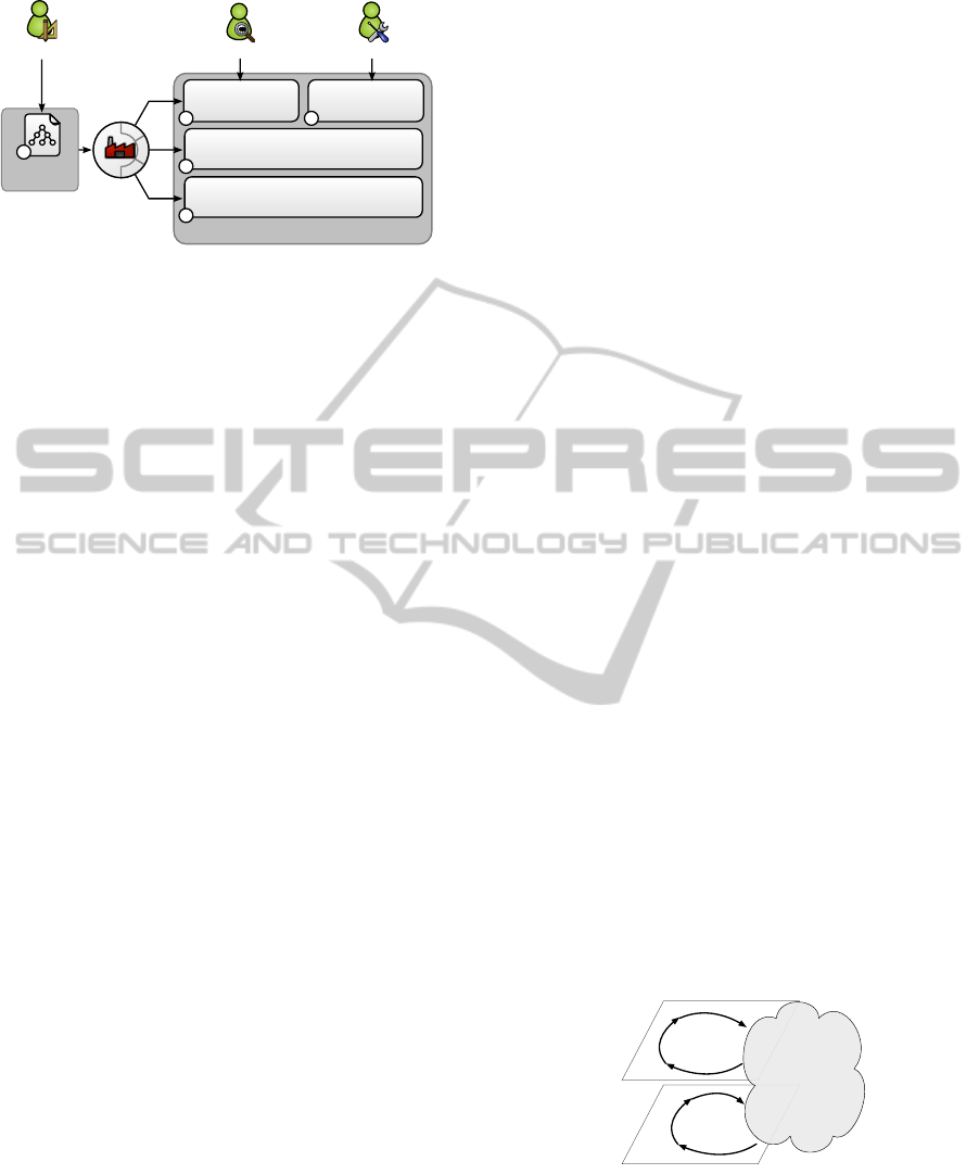
As depicted in Figure 2, the DiaSuite tool suite
leverages the SCC paradigm to support each stage of
the development process, from design to deployment.
At the design stage, the DiaSpec language provides
SCC-specific declaration constructs (stage
À
in Fig-
ure 2). These constructs cover both the functional
aspects of an application, such as data and control
flows (Cassou et al., 2011), and the non-functional
aspects, such as QoS (Gatti et al., 2011) and error
handling (Mercadal et al., 2010).
From a DiaSpec description, a programming frame-
work is generated to guide and support the programmer
1
http://ardrone.parrot.com
PECCS2013-InternationalConferenceonPervasiveandEmbeddedComputingandCommunicationSystems
178
Execution platform back-end
Programming framework
Designers
Testers
Developers
DiaSpec
Compiler
Application
Design
Implementation Support
1
Simulation
Application
2
4 3
5
Figure 2: The DiaSuite tool-based methodology.
(stages
Á
and
Â
in Figure 2). Additionally, the Dia-
Spec compiler generates testing support, targeting a
simulator specific to a given domain (stage
Ã
in Fig-
ure 2). Finally, DiaSuite offers support for deploying
an application using several distributed systems tech-
nologies such as Web Services, RMI and SIP (stage
Ä
in Figure 2). More details about DiaSuite can be found
in our previous publications (Cassou et al., 2009; Cas-
sou et al., 2011).
2.2 Flight Guidance Application
To illustrate the DiaSuite development methodology
for dependable SCC applications, we choose an appli-
cation of aircraft flight guidance. Because it is safety
critical, this application has to respect stringent high-
level requirements.
The flight guidance application is in charge of the
aircraft navigation and is under the supervision of the
pilot (Miller, 1998). For example, the pilot can di-
rectly specify parameters during the flight (e.g., the
altitude) or define a flight plan that is automatically
followed. Each parameter is handled by a specific
navigation mode (e.g., altitude mode, heading mode).
Once a mode is selected by the pilot, the flight guid-
ance application is in charge of operating the ailerons
and the elevators to reach the target position. For ex-
ample, if the pilot specifies a heading to follow, the
application compares it to the current heading, sensed
by devices such as the Inertial Reference Unit (IRU),
and maneuvers the ailerons accordingly. Each naviga-
tion mode is generally associated to a functional chain,
representing a chain of computations, from sensors to
actuators (Windsor and Hjortnaes, 2009).
In the avionics domain, safety analyses are con-
ducted to identify hazardous situations, resulting in
safety requirements (ARP-4761, 1996). Here are some
examples of high-level requirements for the flight guid-
ance application, as defined by domain experts:
Req1.
The execution time of the functional chain as-
sociated with the heading mode must not exceed
650 ms.
Req2.
The freshness of the navigation data used by
the application must be less than 200 ms.
Req3.
The malfunction or failure of a sensor must be
systematically signaled to the pilot, within 300 ms.
Req4.
A navigation mode should be deactivated
safely if a sensor involved in its computation fails.
Translating these requirements into a coherent de-
sign and ensuring their traceability across the devel-
opment process is mandatory for the certification,
strongly suggesting an integrated design-driven de-
velopment methodology like DiaSuite.
3 DESIGN
This section presents our design approach for depend-
able SCC applications and the validation support gen-
erated at the design stage. These contributions are
illustrated with the heading mode of the flight guid-
ance application, introduced in Section 2.2.
3.1 Our Approach
Like a programming paradigm, the DiaSuite design
paradigm provides SCC-specific concepts and abstrac-
tions to solve a software engineering problem. How-
ever, these concepts and abstractions are dedicated to
a design style, raising the level of abstraction above
programming. In this paper, we propose to use this
paradigm to uniformly describe both the functional and
non-functional aspects of an application. As shown
in Figure 3, our approach consists of layering the de-
sign of an application into the logic of the functional
plane and the supervision of the non-functional as-
pects. When a non-functional situation is detected at
the functional layer (e.g., a device failure), an event is
raised, giving control to the supervisory layer.
Compute
Control
Sense
Supervisory
Functional
Environment
Compute
Control
Sense
Figure 3: Layered view of the SCC paradigm.
This layered design allows to factorize the supervi-
sory treatments such as error recovery. For example,
the
Req4
requirement entails to deactivate the navi-
gation modes that rely on faulty sensors. In this case,
if a navigation sensor fails, an event (i.e., an error) is
Design-drivenDevelopmentofDependableApplications-ACaseStudyinAvionics
179

raised, giving control to a supervisory chain of oper-
ations, aimed to deactivate the dependent navigation
modes.
The design of the flight guidance application can
thus be decomposed into several functional and super-
visory chains: one functional chain for each navigation
mode and one supervisory chain for each supervisory
treatment (e.g., reconfiguration, logging, pilot warn-
ing). In the rest of this section, we focus on the func-
tional chains of the heading mode and the supervisory
chain dedicated to deactivating the dependent naviga-
tion modes.
3.2 Functional Layer
Following the SCC paradigm, the DiaSpec design lan-
guage provides specific declarations for entities, con-
text and controller components. An entity is defined
as a set of sensing and actuating capabilities. Figure 4
presents the taxonomy of the entities used by the head-
ing mode of the flight guidance application. The
IRU
entity senses the position, the heading and the roll of
the plane from the environment, as indicated by the
source
keyword. The
NavMMI
entity abstracts over the
pilot interaction and directly provides the target head-
ing set by the pilot. The
Aileron
entity provides the
Control
interface to act on the environment, as indi-
cated by the
action
keyword. The high-level nature
of the entity declaration facilitates the integration of
Commercial Off-The-Shelf (COTS) components: any
implementation complying with the entity declaration
can be used by an application.
d e v i c e IRU {
s o u r c e h e a d i n g as F l o a t [ f re q u e nc y 200 ms ] ;
s o u r c e p o s i t i o n a s C o o r d i n a t e s ;
s o u r c e r o l l as F l o a t ;
. . .
a c t i o n D e a c t i v a t e ;
r a i s e s F a i l u r e E x c e p t i o n ;
}
d e v i c e NavMMI {
s o u r c e t a r g e t H e a d i n g a s F l o a t ;
. . .
a c t i o n Di sa b le M od e ;
a c t i o n D i s p l a y ;
}
a c t i o n C o n t r o l {
i n c l i n e ( t a r g e t R o l l as F l o a t ) ;
}
d e v i c e A i l e r o n {
a c t i o n C o n t r o l ;
}
Figure 4: Extract of the flight guidance taxonomy.
This design can be enriched with QoS and error-
handling declarations. For example, in Figure 4, the
IRU
entity is declared as raising an error of type
FailureException
. Figure 4 specifies that the
IRU
entity produces the
heading
information with a fre-
quency of 200 ms. For more details about these non-
functional declarations, the reader can refer to previous
publications (Mercadal et al., 2010; Gatti et al., 2011).
Using this taxonomy of entities, the specification of
an application is defined using context and controller
components. For example, in the design of the heading
mode, the
IntHeading
context component computes
an intermediate heading from the current plane head-
ing given by the
IRU
entity and the target heading given
by the
NavMMI
entity. From this intermediate heading
and the current plane roll (i.e., its rotation on the longi-
tudinal axis) given by the
IRU
entity, the
TargetRoll
context component computes a target roll. This tar-
get roll is used by
AileronController
to control the
ailerons and reach the target heading.
The specification of an SCC component is illus-
trated in Figure 5. This DiaSpec fragment declares the
IntHeading
context component as producing an inter-
mediate heading of a
Float
type from values of two
input entities, declared with the
source
keyword. The
control flow of this process is specified by an interac-
tion contract introduced by the
interaction
clause. It
declares that, when
IntHeading
receives a
heading
information from the
IRU
entity, it may access the
targetHeading
value provided by the
NavMMI
entity.
The
always publish
clause specifies that the context
systematically publishes a value once it receives a
heading
information. Alternatively, a context compo-
nent can be declared as either maybe or never publish-
ing a result.
c o n t e x t I n t H e a d i n g a s F l o a t {
s o u r c e h e a d i n g from IRU ;
s o u r c e t a r g e t H e a d i n g from NavMMI ;
i n t e r a c t i o n {
when p r o v i d e d h e a d i n g from IRU ;
g e t t a r g e t H e a d i n g from NavMMI
i n 100 ms [ mandatory c a t c h ] ;
al w ay s p u b l i s h ;
}
}
Figure 5: Specification of IntHeading.
In the interaction contract of
IntHeading
, the re-
sponse time of
NavMMI
has to be at most 100 ms.
The
[mandatory catch]
annotation indicates that
the
IntHeading
context must compensate the errors
when accessing
targetHeading
data. In contrast, the
[skipped catch]
annotation indicates that a context
is not allowed to handle the errors.
3.3 Supervisory Layer
Figure 6 summarizes the design of the heading mode
by a data-flow directed graph, where a node is an SCC
component and the edges indicate data exchange be-
tween the components. This figure shows another QoS
declaration: a Worst Case Execution Time (WCET) is
specified on the
Aileron
controller to cope with the
Req1 requirement.
PECCS2013-InternationalConferenceonPervasiveandEmbeddedComputingandCommunicationSystems
180
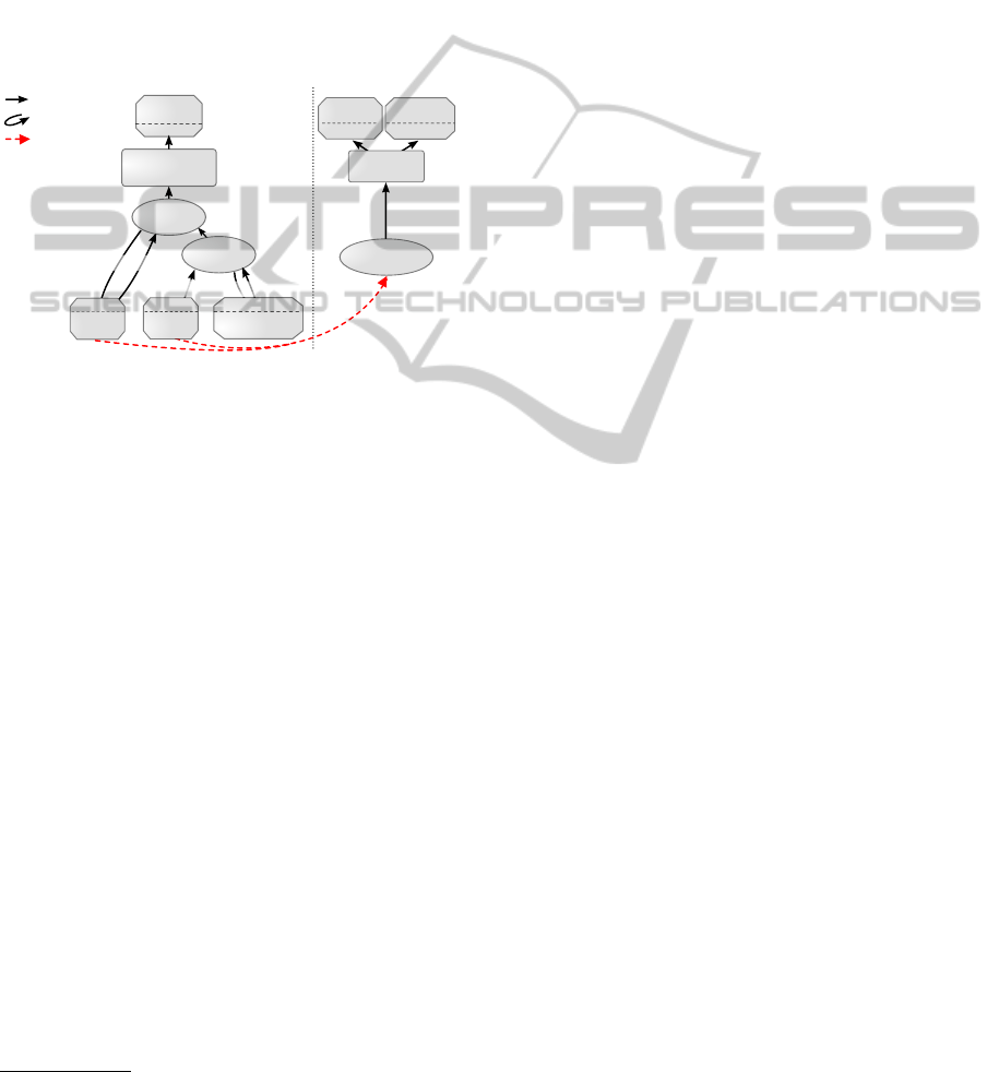
Alongside the application logic, supervisory treat-
ments can be specified in DiaSpec using separate SCC
chains. In the avionics domain, these treatments typi-
cally involve monitoring the application and triggering
reconfigurations, as required by the
Req3
and
Req4
requirements expressed in Section 2.2. Specifically,
these treatments allow to (1) inform the pilot in case
of a device failure or unavailable data, (2) deactivate
the modes that depend on unavailable data, and (3) log
information for maintenance purposes. For example,
the right part of Figure 6 depicts the supervisory chain
corresponding to the deactivation of the dependent
navigation modes.
Aileron
Control
Mode
Controller
Aileron
Controller
TargetRoll
Data
Availability
IntHeading
Exceptional
Event
Data access
Data publishing
IRU
roll
IRU
Deactivate
NavMMI
DisableMode
[200ms]
[200ms, skipped]
[100ms, mandatory]
NavMMI
targetHeadingheading
[650ms WCET]
IRU
Figure 6: Extract of the flight guidance application design.
These supervisory chains are specified with respect
to non-functional information defined in the taxon-
omy and the application design. For instance, errors
raised by entities or violations of timing constraints
are used as sources of information for the supervisory
treatments. In Figure 6, the availability of
IRU
data
is checked through the
DataAvailability
context
component and is then used by the
ModeController
component to enable/disable navigation modes and
deactivate the faulty sensors.
3.4 Verification Support
Because the DiaSpec design language makes flow
information explicit, a range of properties can be
checked at design time. Indeed, a formal model can
be generated from a DiaSpec specification, allowing
the early verification of coherence and conformance.
Unlike our previous work (Cassou et al., 2011), we
now generate models expressed with timed automata,
capturing time-related declarations. A DiaSpec speci-
fication is translated into a network of timed automata
where each automaton describes the behavior of a Dia-
Spec component.
2
The resulting network of timed au-
tomata allows to verify safety properties using model-
checking techniques. Here, we use UPPAAL, an
2
A detailed presentation of this translation can be found
at http://diasuite.inria.fr/validation.
integrated tool environment dedicated to modeling,
validation and verification of networks of timed au-
tomata (Behrmann et al., 2004). To illustrate this early
verification process, we present examples of coher-
ence and conformance verifications on the design of
the flight guidance application.
Coherence Verification.
Incoherence between the
time-related constraints can be automatically detected
by the UPPAAL model checker. Time-related proper-
ties depend on communication assumptions (e.g., asyn-
chronous/synchronous communication, data buffer-
ing). These assumptions are expressed in terms of
parameters of the generated UPPAAL model. In the
model of the heading mode, we specify that the com-
ponents have no buffer and thus consume values im-
mediately. In this case, a deadlock state is detected
if the
NavMMI
takes more than 200 ms to answer to a
request from the IntHeading context component. In-
deed, this context component is not able to handle the
heading data published every 200 ms by the
IRU
entity.
This verification has led us to enrich the design with
a timing constraint indicating that the response time
of
NavMMI
has to be at most 100 ms. A more complex
example is the interaction between the
TargetRoll
context component and the
IRU
entity. A deadlock
is detected when the pulling process takes more than
300 ms. The shortest counter-example includes three
data requests and thus cannot be easily identified by
hand.
Conformance Verification.
We use properties
based on temporal logic to express high-level require-
ments and check them on the design of the applica-
tion. The UPPAAL model checker relies on a sub-
set of TCTL (Timed Computation Tree Logic) (Hen-
zinger et al., 1994). An example of TCTL prop-
erties is “
IRU.Failure NavMMI.DisableMode
”,
corresponding to the
Req4
requirement. When
the
IRU
automaton is in the
IRU.Failure
state,
the
NavMMI
automaton will eventually be in the
NavMMI.DisableMode
state, which corresponds to the
deactivation of the navigation modes that depend on
the IRU sensor.
Even if conformance and coherence cannot be fully
guaranteed at design time, providing such validation
support guides the design with regard to the high-level
requirements. Indeed, when a property is not satis-
fiable, a counter-example is generated by UPPAAL,
helping the designer to improve the DiaSpec specifica-
tion. Moreover, our generative approach ensures that
the implementation is conform to the design, preserv-
ing these properties in the subsequent stages of the
development process.
Design-drivenDevelopmentofDependableApplications-ACaseStudyinAvionics
181

4 IMPLEMENTATION
When developing dependable applications, a key goal
is to preserve the high-level requirements throughout
the development process. To do so, the DiaSuite ap-
proach relies on a compiler that generates a dedicated
programming framework from a DiaSpec design. As
depicted in Figure 2, the compiler takes as input the
DiaSpec specification of the application and gener-
ates a dedicated Java programming framework that
ensures the conformance between the design and the
implementation (Cassou et al., 2011).
For example, Figure 7 shows the abstract class
generated from the specification of the
IntHeading
context component. This abstract class guides the de-
veloper by providing high-level operations for entity
binding and component interactions. Additionally, our
strategy to generate an abstract class relies on the Java
language and its type system to enforce the declared
interaction contracts. As shown in Figure 8, when ex-
tending the
AbstractIntHeading
abstract class, the
developer is required to implement the
onHeading-
FromIRU
abstract method to receive a value published
by this device. In addition to this value, this method is
passed support objects to request data from a device
(binding).
p u b l i c a b s t r a c t c l a s s A b s t r a c t I n t H e a d i n g {
p u b l i c a b s t r a c t F l o a t onHeadingFr o mIRU (
F l o a t h ea d i n g , B i n d i n g b i n d i n g ) ;
. . .
}
Figure 7: Extract of the AbstractIntHeading class
p u b l i c c l a s s I n t H e a d i n g e x t e n d s A b s t r a c t I n t H e a d i n g {
p u b l i c F l o a t o nHeadingFromIRU ( F l o a t h e ad i ng , B i n d i n g
b i n d i n g ) {
NavMMI mmi = b i n d i n g . navMMI ( ) ;
F l o a t t a r g e t H e a d i n g = mmi . g e t T a r g e t H e a d i n g (
new T a r g e t H e a d i n g C o n t i n u a t i o n ( ) {
p u b l i c F l o a t o n E r r o r ( ) {
r e t u r n DEFAULT_VALUE ; } } ) ;
r e t u r n
c o n t r o l l e r P I D . c o mpu t e ( he a d i n g , t a r g e t H e a d i n g ) ;
}
}
Figure 8: Extract of the
IntHeading
context implementa-
tion.
The inversion of control principle is uniformly ap-
plied to an SCC-generated programming framework to
guarantee that the interaction between the components
is conform to the design. Specifically, the abstract
methods to be implemented by the developer are only
called by the framework, ensuring that a DiaSpec soft-
ware system is compliant with its DiaSpec design.
Similarly, the non-functional declarations are trace-
able throughout the implementation stage by generat-
ing dedicated programming support. For example, the
IRU
entity was declared in the taxonomy (Figure 4)
as raising
FailureException
errors. Consequently,
a specific method is generated in the corresponding
entity abstract class to allow error signaling to be in-
troduced by the developer when implementing an in-
stance of this entity (Mercadal et al., 2010). Another
example is the
mandatory catch
declaration in the
IntHeading
interaction contract presented in Figure 5.
This declaration imposes the
IntHeading
implemen-
tation to handle potential errors when requesting the
targetHeading
data from
NavMMI
. As shown in Fig-
ure 8, this mandatory error handling is enforced by in-
troducing a continuation parameter in the method sup-
plied to the developer to request the
targetHeading
data (i.e.,
getTargetHeading
). This continuation pro-
vides a default value in case of an error.
Timing constraints specified at design time are also
traceable in the generated programming framework.
Indeed, these constraints are automatically monitored
in the programming framework (Gatti et al., 2011). For
instance, this monitoring layer measures the time spent
by the
IntHeading
context component to retrieve the
targetHeading
data. If this time is greater than 100
ms (as specified in Figure 5), an error is automatically
raised by the framework.
As shown in Section 3, the supervisory treatments
are handled independently from the functional treat-
ments. This separation of concerns allows a developer
to focus on a specific non-functional aspect. For ex-
ample, the developer of the
DataAvailability
con-
text component can concentrate on implementing al-
gorithms to detect data availability. Because of the
programming framework support, the developer does
not need to mix supervisory operations, to detect and
handle errors, with the functional treatments.
5 TESTING
The implementation of each SCC chain can be tested
independently. For example, the functional aspect of
the application can be tested using a simulated exter-
nal environment. The taxonomy definition allows to
validate the functional implementation using mock-up
entities that rely on the simulated environment. This is
done without any impact on the rest of the application.
In avionics, it is required to verify the behavior of
the application in specific environmental conditions.
Because some scenarios are difficult to create (e.g.,
extreme flight conditions), we provide a testing sup-
port that relies on a flight simulator, namely Flight-
Gear (Perry, 2004), to simulate the external environ-
ment.
Using a Java library that interfaces with FlightGear,
the testers can easily implement simulated versions of
PECCS2013-InternationalConferenceonPervasiveandEmbeddedComputingandCommunicationSystems
182

entities. Figure 9 presents an extract of the implemen-
tation of a simulated IRU.
p u b l i c c l a s s S i m u la te dI RU e x t e n d s A b s t r a c t I R U
imp l em e nts S i m u l a t o r L i s t e n e r {
p u b l i c S im ul at ed I R U ( FGModel model ) {
model . a d d L i s t e n e r ( t h i s ) ;
}
p u b l i c v o i d s i m u l a t i o n U p d a t e d ( FGModel model ) {
p u b l i s h P o s i t i o n ( model . g e t I n e r t i a l P o s i t i o n ( ) ) ;
}
}
Figure 9: Extract of the simulated IRU class.
The
SimulatedIRU
entity is implemented by in-
heriting the
AbstractIRU
class, provided by the pro-
gramming framework. To interact with the simulated
environment, the entity implements the
Simulator-
Listener
interface. This interface defines a method
named
simulationUpdated
, which is called periodi-
cally by the simulation library. The
model
parameter
allows to read/write the current state of the FlightGear
simulator. In Figure 9, the position of the plane is
published by calling the
publishPosition
method
of the AbstractIRU class.
Figure 10: Screenshot of a simulated flight.
Once the simulated entities are implemented, the
flight guidance application is tested by controlling a
simulated plane within FlightGear. An example of
testing scenarios is to provide a desired heading via the
autopilot interface of the flight guidance application
and to verify that the application controls the ailerons
of the simulated plane as expected. Figure 10 presents
a screenshot of our testing environment. In the main
window, the FlightGear simulator allows to control and
visualize the simulated plane. In the top-left corner, the
autopilot interface allows testers to select a navigation
mode. In this case, the "Route Manager" mode is
selected to follow the flight plan defined via the map
displayed in the bottom-left corner.
The simulated environment is also useful for test-
ing the supervisory SCC chains. Device failures can be
directly simulated using FlightGear. We also provide
a simple testing support to inject errors from the sim-
ulated entities as illustrated by the
FaultInjector
window in the top-right corner. Then, the window in
the bottom-right of the screenshot displays the errors
monitored by the application. This particular testing
support eases the verification of the conformance with
the requirements such as the
Req3
requirement pre-
sented in Section 2.2
Finally, it is required to realize integration testing
on a test bench to ensure that the application behaves
correctly for a specific deployment configuration. An
advantage of our simulation support is that simulated
and real entities can be combined in a hybrid environ-
ment. Indeed, as both real and simulated versions of
an entity extend the same abstract class, the nature
of an entity has no impact on the rest of the applica-
tion. Deploying an application on a test bench is a
daunting task that has to be repeated each time an error
is detected. Testing by simulation may avoid some
unnecessary deployments.
6 ASSESSMENT
We now outline the benefits of our approach, fo-
cusing on the coherence and conformance verifica-
tion. As shown in the previous sections, we have
developed an avionics flight guidance application and
tested it on a realistic flight simulator, namely Flight-
Gear (Perry, 2004). Additionally, we have duplicated
this case study in the context of the commercial Parrot
AR.Drone system.
3
6.1 Coherence
To ensure coherence at design time, the DiaSuite
methodology relies on a unique design language. Un-
like independent views (e.g., the collection of UML
diagrams), DiaSpec integrates functional and non-
functional declarations, contributing to prevent most
inconsistencies. For example, the coherence between
error-handling declarations can be statically checked
as they directly refine the interaction contracts describ-
ing the control flow. If the designer declares an entity
as raising an exception, compile-time verifications en-
sure that there is an error-handling declaration for each
component requiring data from this entity. Concerning
the QoS declarations, their coherence is directly veri-
fied on the formal model generated from the DiaSpec
specification. Indeed, any inconsistencies between the
timing constraints result in a deadlock, as shown in
Section 3.
At implementation time, the coherence between
the error-handling declarations is automatically pre-
3
The DiaSpec specification and a video demonstrating
this application are available at http://diasuite.inria.fr/ avion-
ics/ardrone.
Design-drivenDevelopmentofDependableApplications-ACaseStudyinAvionics
183

served thanks to the generated programming frame-
work. Indeed, the support generated for error handling,
such as in the
DataAvailability
context component
presented in Section 4, prevents developers from im-
plementing ad-hoc code for error propagation. Con-
cerning the QoS declarations, the generated support
consists of monitors integrated in the programming
framework. These guards do not ensure coherence
by themselves but guide the coherence verification at
runtime. Indeed, when a QoS contract is not fulfilled,
a specific exception is raised, pinpointing the involved
component.
6.2 Conformance
To ensure the conformance with respect to the high-
level requirements, we provide validation support
along the development process. We illustrate how
this support guides the conformance verification us-
ing the
Req3
requirement. This requirement indicates
that the malfunction or failure of a sensor must be
systematically signaled to the pilot, within 300 ms.
At design time, this requirement leads to the spec-
ification of an SCC supervisory chain dedicated to
the signaling of the failure to the pilot. The early-
verification support presented in Section 3 allows to
statically verify that an exceptional event raised by the
IRU
entity systematically results in the triggering of
the Display action on the NavMMI entity.
At implementation time, the generation of a pro-
gramming framework ensures the conformance of the
application with the data and control flow specifica-
tions as demonstrated in previous work (Cassou et al.,
2011). However, the time-related aspect of the
Req3
requirement cannot be verified at design time as it
depends on runtime specificities (e.g., the properties
of the execution platform). To ease the verification
of such requirements, the programming framework
provides dedicated monitors to detect the violation of
the time-related constraints during the testing stage.
Moreover, the generated testing support provides error-
injection capabilities, allowing to validate the
Req3
requirement, even if the
IRU
entity is not yet imple-
mented.
7 RELATED WORK
Several design-driven development approaches are
dedicated to dependable applications.
In the domain of architecture description lan-
guages, the Architecture Analysis & Design Language
(AADL) is a standard dedicated to real-time embed-
ded systems (Feiler, 2006). AADL provides language
constructs for the specification of software systems
(e.g., component, port) and their deployment on execu-
tion platforms (e.g., thread, process, memory). Using
AADL, designers specify non-functional aspects by
adding properties on language constructs (e.g., the pe-
riod of a thread) or using language extensions such
as the Error Model Annex.
4
The software design con-
cepts of AADL are still rather general purpose and give
little guidance to the designer. At the expense of gener-
ality, our approach makes explicit domain-specific con-
cepts in the design specification of dependable applica-
tions, namely sensors, contexts, controllers, actuators.
This approach enables further development support for
the design, programming and testing stages.
As AADL is a standard, a lot of research has been
devoted to provide it with analysis and development
tool support. For example, Dissaux et al. present per-
formance analysis of real-time architectures (Dissaux
and Singhoff, 2008). They propose a set of AADL de-
sign patterns to model real-time issues, such as thread
synchronization. For each pattern, they list a set of
performance criteria (e.g., the bounds on a thread wait-
ing time due to access data) that can be checked with
a performance analysis tool (Singhoff et al., 2004).
In comparison, our approach allows to specify timing
constraints on component interactions, enabling the
verification of time-related properties at a higher level
of abstraction. As AADL mainly focuses on deploy-
ment concerns, it is complementary to our approach
and could be used for the deployment specification
and analysis of applications designed with DiaSpec.
While most ADLs provide little or no implementation
support, the Ocarina environment allows the genera-
tion of programming support dedicated to an AADL
description (Hugues et al., 2008). However, this pro-
gramming support consists of glue code for a real-time
middleware and does not guide nor constrain the ap-
plication logic implementation.
In model-driven engineering, several approaches
focus on dependable applications. For example,
Burmester et al. propose a development approach
dedicated to mechatronic systems (Burmester et al.,
2004). This approach is based on a domain-specific
extension of UML for real-time systems. To allow
the formal verification of a whole mechatronic system,
the authors propose to develop a library of coordina-
tion patterns that define specific component roles, their
interactions and real-time constraints. Then, the com-
ponents of the application are built using this library
of patterns by specifying their roles and additional be-
havior details. The approach comprises tool support
for the specification, verification and source code syn-
4
The Error Model Annex is a standardized AADL exten-
sion for the description of errors (Vestal, 2005).
PECCS2013-InternationalConferenceonPervasiveandEmbeddedComputingandCommunicationSystems
184

thesis as a plug-in for the Fujaba tool suite (Burmester
et al., 2005). The use of coordination patterns can be
seen as a paradigm that guides the design of mecha-
tronic systems. Contrary to ours, their approach does
not provide support for error handling but focuses on
the time-related aspects.
Another development methodology for dependable
applications is SCADE (Safety Critical Application
Development Environment) (Dion, 2004). SCADE is
based on a synchronous language and relies on hierar-
chical state machines for the specification of depend-
able applications. An application is specified using
state machines, enabling the verification of coherence
at design time. The synchronous paradigm ensures by
construction the determinism of a specification, and
thus eases these verifications. The approach abstracts
over physical time allowing real-time properties to be
verified at the code level. Our design methodology is
similar to this approach but lifts constraints inherent
to the determinism of the specification. SCADE could
be used to specify more precisely the internal behavior
of critical DiaSpec components.
8 CONCLUSIONS AND FUTURE
WORKS
In this paper, we have shown the benefits of the Dia-
Suite methodology for the development and the veri-
fication of dependable applications. We have applied
this methodology to a realistic case study in the avion-
ics domain and covered the entire development pro-
cess, from design to testing, leveraging an existing
flight simulator.
We are currently working on the specification of
fault tolerance strategies to improve the generated sup-
port for error handling. Another direction concerns the
deployment stage. We plan on reusing existing avion-
ics deployment technologies to provide deployment
support.
REFERENCES
Amey, P. (2002). Correctness by Construction: Better Can
Also Be Cheaper. CrossTalk: the Journal of Defense
Software Engineering, 2:24–28.
ARP-4761 (1996). ARP-4761, Guidelines and Methods for
Conducting the Safety Assessment Process on Civil
Airborne Systems and Equipment (SAE).
Avizienis, A., Laprie, J., Randell, B., and Landwehr, C.
(2004). Basic Concepts and Taxonomy of Depend-
able and Secure Computing. Dependable and Secure
Computing, IEEE Transactions on, 1(1):11–33.
Behrmann, G., David, A., and Larsen, K. (2004). A Tutorial
on Uppaal. Formal methods for the design of real-time
systems, pages 33–35.
Burmester, S., Giese, H., Hirsch, M., Schilling, D., and
Tichy, M. (2005). The Fujaba Real-Time Tool Suite:
Model-Driven Development of Safety-Critical, Real-
Time Systems. In ICSE’05: Proceedings of the 27th
International Conference on Software Engineering,
pages 670–671. ACM.
Burmester, S., Tichy, M., and Giese, H. (2004). Model-
ing Reconfigurable Mechatronic Systems with Mecha-
tronic UML. In Proceedings of Model-Driven Archi-
tecture: Foundations and Applications (MDAFA 2004),
Linköping, Sweden, pages 155–169.
Cassou, D., Balland, E., Consel, C., and Lawall, J. (2011).
Leveraging Software Architectures to Guide and Verify
the Development of Sense/Compute/Control Applica-
tions. In ICSE’11: Proceedings of the 33rd Inter-
national Conference on Software Engineering, pages
431–440. ACM.
Cassou, D., Bertran, B., Loriant, N., and Consel, C. (2009).
A Generative Programming Approach to Developing
Pervasive Computing Systems. In GPCE’09: Proceed-
ings of the 8th International Conference on Generative
Programming and Component Engineering, pages 137–
146. ACM Press.
Cassou, D., Bruneau, J., Consel, C., and Balland, E. (2011).
Towards A Tool-Based Development Methodology for
Pervasive Computing Applications. Software Engineer-
ing, IEEE Transactions on, PP(99).
Dion, B. (2004). Correct-By-Construction Methods for the
Development of Safety-Critical Applications. SAE
transactions, 113(7):242–249.
Dissaux, P. and Singhoff, F. (2008). Stood and Cheddar:
AADL as a Pivot Language for Analysing Perfor-
mances of Real Time Architectures. In Proceedings of
the European Real Time System conference. Toulouse,
France.
Feiler, P. (2006). The Architecture Analysis & Design Lan-
guage (AADL): An Introduction. Technical report,
DTIC Document.
Gatti, S., Balland, E., and Consel, C. (2011). A Step-wise
Approach for Integrating QoS throughout Software
Development. In FASE’11: Proceedings of the 14th
European Conference on Fundamental Approaches to
Software Engineering, pages 217–231.
Henzinger, T. A., Nicollin, X., Sifakis, J., and Yovine, S.
(1994). Symbolic Model Checking for Real-Time Sys-
tems. Inf. Comput., 111(2):193–244.
Hugues, J., Zalila, B., Pautet, L., and Kordon, F. (2008).
From the Prototype to the Final Embedded System Us-
ing the Ocarina AADL Tool Suite. ACM Transactions
on Embedded Computing Systems, 7:1–25.
Lasnier, G., Zalila, B., Pautet, L., and Hugues, J. (2009).
OCARINA: An Environment for AADL Models Anal-
ysis and Automatic Code Generation for High Integrity
Applications. Reliable Software Technologies–Ada-
Europe 2009, pages 237–250.
Littlewood, B. and Strigini, L. (2000). Software Reliability
and Dependability: a Roadmap. In ICSE’00: Pro-
ceedings of the Conference on The Future of Software
Engineering, pages 175–188. ACM.
Design-drivenDevelopmentofDependableApplications-ACaseStudyinAvionics
185

Mercadal, J., Enard, Q., Consel, C., and Loriant, N. (2010).
A Domain-Specific Approach to Architecturing Error
Handling in Pervasive Computing. In OOPSLA’10:
Proceedings of the Conference on Object Oriented
Programming Systems Languages and Applications,
volume 45, pages 47–61.
Miller, S. (1998). Specifying the Mode Logic of a Flight
Guidance System in CoRE and SCR. In FMSP’98:
Proceedings of the Second Workshop on Formal Meth-
ods in Software Practice, pages 44–53. ACM.
Perry, A. R. (2004). The FlightGear Flight Simulator. In
Proceedings of the USENIX Annual Technical Confer-
ence.
Shaw, M. (1995). Beyond Objects: A Software Design
Paradigm Based on Process Control. SIGSOFT Soft-
ware Engineering Notes, 20:27–38.
Singhoff, F., Legrand, J., Nana, L., and Marcé, L. (2004).
Cheddar: a Flexible Real Time Scheduling Framework.
ACM SIGAda Ada Letters, XXIV:1–8.
Taylor, R. N., Medvidovic, N., and Dashofy, E. M. (2009).
Software Architecture: Foundations, Theory, and Prac-
tice. Wiley Publishing.
Vestal, S. (2005). An Overview of the Architecture Analysis
& Design Language (AADL) Error Model Annex. In
AADL Workshop.
Volter, M., Stahl, T., Bettin, J., Haase, A., and Helsen, S.
(2006). Model-driven Software Development: Technol-
ogy, Engineering, Management. John Wiley and Sons
Ltd.
Windsor, J. and Hjortnaes, K. (2009). Time and Space Par-
titioning in Spacecraft Avionics. In SMC-IT’09: Pro-
ceedings of the 3rd IEEE International Conference on
Space Mission Challenges for Information Technology,
pages 13–20. IEEE.
PECCS2013-InternationalConferenceonPervasiveandEmbeddedComputingandCommunicationSystems
186
