
Advanced Trajectory Engineering of Diffraction-Resisting
Laser Beams
Ioannis D. Chremmos
1
, Zhigang Chen
2
, Demetrios N. Christodoulides
3
and Nikolaos K. Efremidis
1
1
Department of Applied Mathematics, University of Crete, Heraklion 71409, Greece
2
Department of Physics and Astronomy, San Francisco State University, San Francisco, California 94132, U.S.A.
3
CREOL/ College of Optics, University of Central Florida, Orlando, Florida 32816, U.S.A.
Keywords: Laser Beams, Bessel Beams, Diffractionless Beams, Accelerating Beams, Trajectory Engineering.
Abstract: We introduce an analytical technique for engineering the trajectory of diffraction-resisting laser beams. The
generated beams have a Bessel-like transverse field distribution and can be navigated along rather arbitrary
curved paths in free space, thus being an advanced hybrid between accelerating and non-accelerating
diffraction-free optical waves. The method involves phase-modulating the wavefront of a Gaussian laser
beam to create a continuum of conical ray bundles whose apexes define a prespecified focal curve, along
which a nearly perfect circular intensity lobe propagates without diffracting. Through extensive numerical
simulations, we demonstrate the great flexibility in the design of a gamut of different beam trajectories.
Propagation around obstructions and self-healing scenarios are also investigated. The proposed wave
entities can be used extensively for light trajectory control in applications such as laser microfabrication,
optical tweezers and curved plasma filamentation spectroscopy.
1 INTRODUCTION
Over the past few years there has been a vivid
interest in optical beams with peculiar diffraction
and propagation properties. The stimulus has been
the broad set of new possibilities and disciplines in
optical micromanipulation, testing and
manufacturing enabled by our ability to navigate the
optical power on appropriately ‘sculpted’ optical
waveforms Grier, 2003); (Andrews, 2008. Such
structured optical beams can be used to overcome
the diffraction limitations in focusing optical power
at long distances and, moreover, to control the
trajectory of light around obstructions and provide
access to otherwise inaccessible regions of the
medium being tested or processed.
Structured laser beams with such advantageous
characteristics can so far be distinguished into two
major categories: non-accelerating and accelerating.
The first category includes the classical diffraction-
free solutions of Maxwell’s equations whose profile
and direction of propagation remains invariant as
they evolve in space. Bessel beams Durnin, 1987
are arguably the most widely known members of
this family and perhaps the only propagation-
invariant beams that have actually been used in
applications successfully Durnin et al., 1987);
(Herman and
Wiggins, 1991. This is owed to their
simple structure, essentially being the result of
interference of a conical bundle of plane waves, that
can be easily obtained by passing a broad Gaussian
laser beam through a conical lens, the axicon Arlt
and Dholakia, 2000); (Herman and
Wiggins, 1991.
The indirect generation of Bessel beams in the
Fourier domain is also straightforward due to the
simple annular shape of their Fourier transform
Durnin et al., 1987. Since their inception, Bessel
beams have found diverse applications in
micromanipulation, atom and nonlinear optics
McGloin and Dholakia, 2005. Other less known
types of non-accelerating diffractionless waves exist,
such as parabolic Bandres et al., 2004) and Mathieu
Gutiérrez-Vega et al., 2000) waves; however they
haven’t been used in applications so far due to the
complicated structure of their wavefront.
The second category involves optical beams
whose profile remains invariant along a transversely
accelerating frame of coordinates. The existence of
these beams was revealed in 2007 when the
quantum-mechanics concept of the Airy wavepacket
10
D. Chremmos I., Chen Z., N. Christodoulides D. and K. Efremidis N..
Advanced Trajectory Engineering of Diffraction-Resisting Laser Beams.
DOI: 10.5220/0004313800100018
In Proceedings of the International Conference on Photonics, Optics and Laser Technology (PHOTOPTICS-2013), pages 10-18
ISBN: 978-989-8565-44-0
Copyright
c
2013 SCITEPRESS (Science and Technology Publications, Lda.)

Berry and Balazs, 1979) was introduced into the
optics domain by Siviloglou and Christodoulides
2007. Airy optical beams were the first diffraction-
free beams with the ability to self-accelerate along a
parabolic trajectory in free space. The
implementation of realistic, finite-energy Airy
optical wavepackets was also found to be
straightforward after it was found that the Fourier
transform of the exponentially truncated Airy
function is a Gaussian modulated by a cubic phase
Siviloglou and Christodoulides, 2007. Soon after
their conception, these finite energy Airy beam
counterparts were generated and demonstrated
experimentally Siviloglou et al., 2007. So far, Airy
laser beams have found several applications for light
trajectory control along ballistic-like paths Hu et al.,
2010, optical manipulation of particles
Christodoulides, 2008, navigation of long-range
surface plasmons Salandrino and Christodoulides,
2010, curved plasma filaments Polynkin et al.,
2009, abruptly autofocusing beams Efremidis and
Christodoulides, 2010 and others. As was later
shown by Bandres 2009, Airy beams are a
fundamental representative of the broader class of
accelerating diffraction-free beams, another member
being parabolic accelerating beams Bandres, 2008.
Notably, the trajectory of any accelerating and
diffractionless beam can only be parabolic.
However, due to their complex spectrum,
accelerating beams, other than Airy, have to date
remained mainly in the theoretical level.
The above review shows that finite-energy
Bessel and Airy beams are to date the most popular
and straightforward to implement forms of
structured light waves with diffraction-resisting
quality and non-accelerating or accelerating
trajectories, respectively. With a Bessel beam, one
can target a perfectly circular intensity lobe along a
straight line and at distances much larger than
implied by the diffraction length of a Gaussian beam
with comparable width, while, with an Airy beam,
one can steer the asymmetric Airy profile over many
diffraction lengths along a parabolic trajectory.
Thus, on the one hand, the fine symmetry of the
Bessel profile is obtained at the cost of an
exclusively straight trajectory, while, on the other
hand, the curved trajectory of Airy beams is
obtained at the cost of an asymmetric intensity
distribution. Moreover, the curve of an Airy beam is
limited to the parabolic law.
In view of these limitations, it is reasonable to
ask if it would be possible to design hybrid beams
that combine the best features of the two classes;
namely to design beams with the symmetry of the
Bessel function that are also capable of self-
accelerating similar to the Airy wavepacket. In
addition, we may require that the trajectory is not
limited to a parabola but it can be shaped rather
arbitrarily. In this announcement we show that the
answer to this question is affirmative.
Specifically, we present a technique for
transforming a standard Gaussian laser beam into a
Bessel-like beam capable of propagating along a
prespecified path with arbitrary shape. The key idea
is to phase-engineer the unmodulated wavefront so
that the emitted rays form a continuum of conical
ray bundles whose apexes or foci write the desired
trajectory. The method is straightforward to
implement experimentally since it only involves
imprinting an appropriately computed phase pattern
on the Gaussian wavefront using a spatial light
modulator SLM or a hologram.
Interestingly, the possibility of Bessel beams
with curved trajectories has recently been addressed
in few works with the aim of producing spiralling
and snaking Bessel beams Jarutis et al., 2009);
(Matijosius et al., 2010); (Morris et al., 2010). The
method proposed in these works is quite
approximate in the sense that the phase modulation
of the beam is derived heuristically in a closed form
and is not the one required to obtain a strict
intersection of the ray cones exactly on the spiralling
or snaking trajectory. Going beyond these fixed
trajectories, we here address the problem of
navigating Bessel beams along arbitrary trajectories
in its most general formulation possible. We show
how the correct phase pattern can be determined
rigorously to ensure that the desired trajectory is
actually a focal trajectory or image curve defined
by the strict intersection of continuously expanding
ray cones. Therefore, the present method can be
used to design not only spiraling helical or snaking
trajectories but any smooth curve. Moreover, a very
clear Bessel profile is obtained that persists for much
longer compared to the reported approximate
approaches.
2 METHOD
To begin, assume that the initial distribution
0
(,)u
of the optical field on the plane
0z
has
the form of a slowly varying envelope
(,)A
modulated by the phase
(,),Q
where ,
stand
for the
,
x
z
coordinates on that plane. For practical
AdvancedTrajectoryEngineeringofDiffraction-ResistingLaserBeams
11

laser beams, the transverse beam width order of
mm is much larger than the optical wavelength
order of μm, hence the propagation of the optical
field can be described very accurately by the scalar
paraxial wave equation
20,
zxxyy
iu u u
whose
solution is given by the Fresnel integral
22
0
2
(,)
(, ,) e
2
xy
i
z
u
uxyz d d
iz
1
where
0
(,) (,)exp[ (,)]uA iQ
and the space
coordinates are normalized by the arbitrary length
scale
in the transverse and by
2
k
in the
longitudinal direction,
2/k
being the vacuum
wavenumber. Note in Eq. 1) that the phase factor
2
exp[ ( ) ]ik z
has been omitted for convenience.
Our goal is to determine the phase modulation
Q
so
that a focal track with a desired shape is created in
0.z
Parametrizing the trajectory of the focus with
the propagation distance, this implies that, at any
,z
rays starting from the input plane must focus at the
point
() ( (), (),),Fz Xz Yz z
where
(),Xz ()Yz
are
given functions. This strict requirement is a critical
difference between our method and that used by
Jarutis et al. 2009 or Morris et al. 2010). In these
works the phase
Q
was heuristically by assuming a
segmentation of an axicon into displaced annuli,
each of which produces a different part of the beam
trajectory. In this way,
Q
was defined in closed
form but the rays do not actually intersect on the
trajectory of the main lobe resulting in a not so clear
Bessel-like profile.
Returning to our analysis, the equations of the
rays are determined by the stationary points in the
phase of the integrand in Eq. 1) and are given by
,
xy
QQ
zz
2
where
,QQ
are the first partials of
.Q Equations
2) imply that the ray starting from point
(,)
on
the input plane travels in the direction of vector
(,,1),QQ
i.e. it is determined by the gradient
,
Q
of the input phase. According to our
requirement, the point ( )Fz must be the intersection
of the bundle of rays starting from all points ( , )
lying on a certain geometric locus
()Cz
on the input
plane
Fig. 1
. This allows us to use Eq.
2) and
rewrite the partial derivatives as
() ()
,
Xz Yz
QQ
zz
3
The correspondence between the point ( , )
and
the distance
,z
at which the rays emitted from the
locus ( )Cz intersect, can be thought to define a
function of two variables ( , )z
which makes the
right-hand sides of Eqs.
3) functions of , .
Equations
3) can then be used to determine the
locus
(),Cz
which is essentially an isoline of
function
(,).z
To this end we note that, if
Q
is
twice continuously differentiable, its mixed partials
must be equal
Clairaut’s theorem), i.e.
QQ
or explicitly from Eqs.
3)
00
zz zz
(4
where
0
0
zXzzXz
zYzzYz
5
and the prime denotes the derivative with respect to
.z
Equation
4) shows that the vector
00
((), ())zz
is normal to the gradient
,
z
and hence tangent to the local isoline, namely
the locus ( ).Cz We may therefore write along ( )Cz
00
0.zd zdh
Figure 1: The idea for producing diffraction-resisting laser
beams with arbitrary trajectories: Conical ray bundles
emitted from expanding circles on the input plane intersect
on a predefined focal line.
Since
z
is constant along an isoline, the above
expression is an exact differential yielding:
22
2
00
zzrz
6
PHOTOPTICS2013-InternationalConferenceonPhotonics,OpticsandLaserTechnology
12

We therefore reach the conclusion that the geometric
locus on the input plane of the starting points of the
rays which intersect at
(),
F
z is a circle with center
00
((), ())zz
given by Eqs. 5) and radius (),rz
which is an arbitrary function for the moment.
Equations 5) also show that the center of this circle
is the point at which the tangent to the focal curve at
()
F
z intersects the input plane. The analysis has
therefore led to a clear physical picture which is
illustrated in Fig. 1: with increasing
z
as the beam
propagates, a continuous focal line is created by the
intersection of the bundles of rays emitted from
circles
()Cz on the input plane with increasing
radius
()rz
and a moving center
00
( ( ), ( )).zz
The radius
()rz together with functions (),
X
z
()Yz
determine the slope with which the rays
interfere to create the focus
()
F
z
and hence the
transverse field distribution around that point on the
plane
.z To see this explicitly, we take into account
that each ray contributes a plane wave to the field in
the region around
().
F
z Defining the local
coordinates around the focal point as
(),
x
xXz
(),
y
yYz
the field contribution of the ray from
point
(,)
of circle ()Cz
is written in the paraxial
approximation as
() , () ,
exp ( )
iXz Yz x y
du iW z
z
(7
where
denotes the inner product and
22
() ()
() ,
2
Xz Yz
Wz Q
z
(8)
Note in Eq. 8 that the two phase terms yield a
constant sum for all points
(,)
of circle
(),Cz
which is a result of the stationarity Eq. 2 of the
phase of the integrand of Eq. 1). Within the paraxial
approximation,
()Wz
is essentially the phase of the
field contributed exactly on
()
F
z
by the ray
emanating from
(,).
Thanks to this remark, it is
now easy to integrate the contributions
du
over the
circle
().Cz Introducing polar coordinates for
convenience as
cos ,x
sin ,y
and
0
cos ,r
0
sin ,r
we find
00
0
,,
2exp
C
XY xy
r
du iW i J
zz
(9)
where the angular spectrum representation of the
Bessel function has been used
2
/cos
0
0
/2e
ir z
J
rz d
Equation 9) shows that, at any distance, the optical
field around the focus is distributed like a Bessel
function modulated by a plane wave, which justifies
the characterization of these waves as Bessel-like.
Moreover, the result indicates explicitly the effect of
the radius function
()rz on the shape of the beam.
To obtain a circular, Bessel-like beam with a lobe
width that remains constant with
,z
and hence
resists diffraction, the radius should be chosen to be
proportional to the propagation distance or
() ,rz z
and then the lobe becomes proportional
to
0
(),J
where
is the normalized transverse
wavenumber. Without loss of generality, we can
choose the transverse length scale
so that
1
which we will assume in the numerical simulations
section.
We now return to the main goal of our analysis
which is the computation of the phase
(,).Q
By
virtue of Eq. 8), the problem is reduced to finding
the phase
()Wz on the circle ()Cz that passes from
the point
(,).
For this purpose, we differentiate
Eq. 8) with respect to
or
) and use Eqs. 3) and
6) to find after some algebra
2
22
2
0
1
2
z
r
Wz X Y d
(10)
where we have arbitrarily set (0) 0.W We have
therefore ended up with a simple algorithm to
compute
Q for given trajectory and radius functions
(), (),():
X
zYzrz
For any point
(,)
on the input
plane, we first solve Eq. 6) for
z
to find the isoline
passing from that point, subsequently substitute into
Eq. 9) to obtain
()Wz and finally obtain (,)Q
from Eq. 8). Thus, in order to design arbitrary
trajectories, the input phase must be computed
numerically through the above algorithm, while
closed form solutions exist only when Eq. 6 can be
explicitly solved for
.z
This is the key finding
reported in this announcement.
Now let us consider a critical issue. It is
important to see that the above algorithm is well
defined only when Eq. 6) has a unique solution for
AdvancedTrajectoryEngineeringofDiffraction-ResistingLaserBeams
13

,z
which means that circles
()Cz
corresponding to
different
z
values must not intersect. Since the
circles are the isolines of function
(,),z
this
requirement is ensured by the finiteness of the
gradient
,
.Q
Differentiating Eq. 6) with respect
to
and
we readily obtain
00
,
00 00
,
z
rr
(11)
where from Eqs. 5) we have
00
,.zX zY
From the above equation, it is clear that the gradient
remains finite if and only if the denominator does
not vanish. This must hold for all points along
()Cz
which we parametrize as
0
cos ,r
0
sin ,r
with 02.
The denominator
is then written
22
cosrr rz X Y
where
1
tan ( / ).YX
Obviously, this
expression remains nonzero when
22
rz z X z Y z
12
which is the sought condition. Note that, under this
condition, the denominator is always positive which,
from Eq. 11), means that the gradient
,
z
points
toward the exterior of the circle (),Cz thus
verifying the expansion of the isolines with
increasing
z
Fig. 1.
The condition of Eq. 12) defines an upper limit
to the propagation distance
m
z
at which the focal
curve can be created and, equivalently, a maximum
circle
m
()Cz
in the exterior of which the above
definition of
Q
fails. Indeed, consider for example
the case of a power law trajectory lying on the plane
0,y with
((),())( ,0).XzYz z
Substituting
into Eq. 12) with
() ,rz z the maximum distance
follows as
1/( 1)
m
[( 1)] ,
v
z
while from Eq.
5) it follows that the maximum circle is centered at
00 max
(, )((1 ) ,0)z
and has radius
m
.rz
Beyond the distance
m
,z
the above analysis is not
applicable and a different phase
Q
must be defined
in the exterior of the maximum circle. To this end,
there is a certain choice that ensures two desired
properties: first, that
Q
remains continuously
differentiable on
m
()Cz
and, second, that the beam
preserves its diffraction-resisting quality for
m
,zz
although it stops accelerating. The choice is to
continue the beam’s trajectory along its tangent line
at the ultimate point
m
()Fz
, i.e. as
mmm
mmm
() () ()( )
() () ()( )
X
zXz Xzzz
Yz Yz Y z z z
13
where
m
.zz
It is then easy to see from Eq. 5)
that the isolines of (,)z
for
m
zz
are concentric
circles with fixed center
0m 0m
(( ), ( ))zz
and
increasing radius
() .rz z
The algorithm for
computing
Q is the same with the
m
zz
regime
using however the new straight trajectory of Eqs.
13). Furthermore, for any point
(,)
in the
exterior of
m
(),Cz
Eq. 6 can be readily solved for
z
giving
22
0m 0m
,zz z
14
namely the distance between points (, )
and
mm
(( ),( ))zz
on the input plane. From Eq. 10)
the corresponding
()Wz
follows easily as
22
mm
mm
[ ( )] [ ( )] 1
() ( )
2
Xz Yz
Wz Wz z z
(15)
and finally the phase follows from Eq. 8
00mm
0m m
,[()]()
()()
QQz zXz
zYz
16
where
22
mm m
0m
[ ( )] [ ( )] 1
()
2
zXz Yz
QWz
(17)
By defining the new coordinates on the input plane
0m 0m
( , ) ( ( ), ( )),zz
the phase from
Eq. 16 can be equivalently written
0mm
(,) (,)( ( ), ( )),QQ XzYz
(18)
where
221/2
[( ) ( ) ] .
Therefore, the phase in
the local polar coordinate system of point
mm
(( ),( ))zz
is the sum of a linear radial term and
the phase of a plane wave. Such a phase is known to
produce a modulated by a plane wave Bessel beam
PHOTOPTICS2013-InternationalConferenceonPhotonics,OpticsandLaserTechnology
14
that propagates along the straight line of Eq.
13).
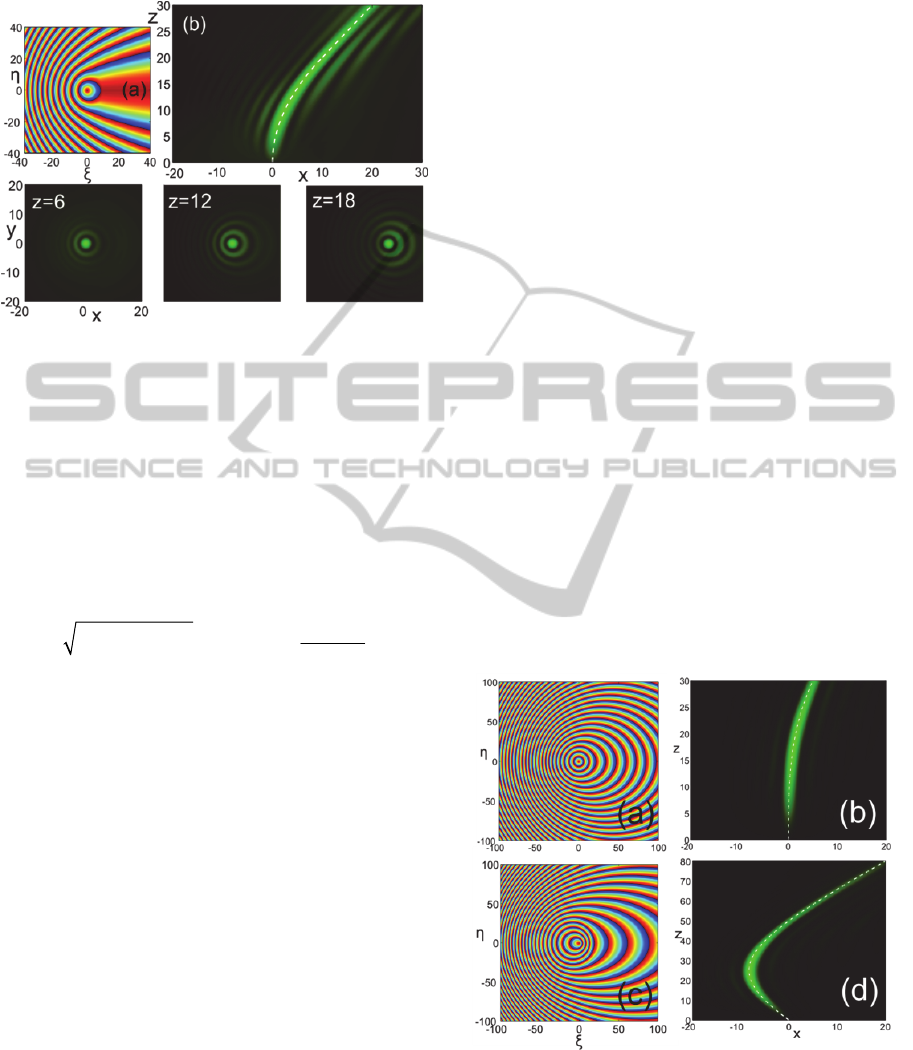
Figure 2: A self-accelerating Bessel-like beam with the
parabolic trajectory
2
0.025 .xz
a Modulo-2π input
phase
Q
b Amplitude evolution on the plane
0.y
The
dashed line is the prespecified analytic trajectory. The
bottom row shows images of the beam amplitude at
different propagation distances.
This becomes evident if one recalls that the input
condition
0
expJix
to the paraxial wave
equation propagates as a tilted Bessel beam
modulated by a plane wave, explicitly
2
22
0
(1 )
() exp .
2
Jxzy ixi z
We have therefore determined through rigorous
analytical steps the phase required to produce a
diffraction-resisting beam with a distant-independent
Bessel profile capable of propagating along an
arbitrary smooth trajectory. In the next Section we
examine numerical simulations of several cases of
the proposed beams as well as scenarios of self-
reconstruction after distortions and propagation
around obstacles.
3 NUMERICAL RESULTS
In Fig. 2 we design a Bessel-like beam with the
parabolic trajectory
2
( ( ), ( )) (0.025 ,0)XzYz z
in
normalized coordinates lying on plane
0.y
The
input Gaussian envelope has a full-width-at-half-
maximum
FWHM
equal to 35 in normalized units.
In
a
, the phase modulation is shown as derived
with the described algorithm and plotted as modulo-
2π. Part
b
depicts the evolution of the field
amplitude on plane
0y
as obtained via a second-
order split-step Fourier simulation. Note how
accurately the trajectory of the main lobe reproduces
the analytically expected trajectory. For this example
the maximum distance is
m
20,z
beyond which
the beam continues along a straight line that matches
the slope of the parabola at the transition point
(,) (20,20).xz The bottom row of Fig. 2 depicts
snapshots of the beam’s transverse profile at
different distances and clearly verifies the expected
Bessel-like pattern. The main lobe is remarkably
symmetric and resistant to diffraction and fits almost
perfectly the central lobe of
0
(),J
as predicted by
Eq. 9. To the best of our knowledge, this is the first
time that a self-accelerating optical beam with an
almost perfect circular lobe is reported.
The clarity of the Bessel central profile observed
in Fig. 2 and in the following simulations is a result
of our strict requirement that the ray cones intersect
exactly on the prespecified focal curve. The reader
can contrast this with the simulation results for the
spiraling Bessel beam in the context of the more
approximate approach by Jarutis et al. 2009. It is
also interesting to observe in Fig. 2 the weak
asymmetric deformation of the surrounding rings
toward the direction of the acceleration. When the
beam enters its final straight track, the acceleration
is zero and the intensity rings obtain again their
symmetric profile.
Figure 3: a Modulo-2π input phase
Q
and b amplitude
evolution on the plane
0y
for a beam with the cubic
trajectory
43
1.85 10 .
x
z
c-d The same results for a
beam with the hyperbolic trajectory
21/21/2
0.8(z 50z 1250) 800 .x
AdvancedTrajectoryEngineeringofDiffraction-ResistingLaserBeams
15
Going beyond parabolic trajectories, Fig. 3
demonstrates the phase patterns and the evolution of
beams with a cubic a-b and hyperbolic c-d
trajectory. Note how the phase patterns appear as
distorted versions of the perfect circular phase
pattern
221/2
[(,) ( ) ]Q
of a Bessel beam,
and that the direction of the distortion stretching is
that of the acceleration of the focal curve. To our
knowledge, this is the first report of beams with a
Bessel-like profile that can follow trajectories
designed at will. In some sense, the possibility of
producing remarkably stable Bessel intensity lobes
that can move along arbitrary curved paths in free
space marries and at the same time enhances the best
features of the standard Bessel and the standard
accelerating beams.
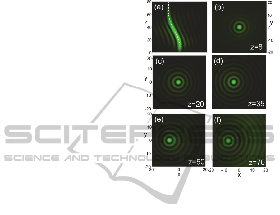
Figure 4 shows another interesting possibility.
Here the trajectory of the beam has been defined
piecewise. Initially the beam propagates straight for
a normalized distance 10 and subsequently detours
along a half-period cosine path with length 50 and
peak-peak distance 8 which guides it to its straight
and parallel to the initial final path. Remarkable is
the resistance that the beam shows against
diffraction, as recorded in the amplitude snapshots at
several distances b-f. At the initial part of the
route a, the beam cannot be distinguished from a
standard Bessel beam. When the acceleration starts,
a weak deformation of the rings is evident toward
the negative x axis c. At around
35,z
i.e. at
the first quarter of the cosine period, the acceleration
of the curve is zero and the deformation disappears
d. Along the second quarter the acceleration
changes sign and the rings start to weakly deform in
the opposite direction e. Along its final straight
track the beam recovers its perfectly symmetric
Bessel profile f. It is thus interesting to observe
the series of rings undergoing ‘elastic’ deformations
under the acceleration experienced at different parts
of the beam trajectory. Such and even more
complicated configurations may be useful for
navigating the optical power to avoid obstructions or
carve elaborate paths with femtosecond pulses inside
bulk glasses, as has recently been demonstrated
using Airy-like beams Mathis et al., 2012.
An example of a beam flowing around an
obstruction is shown in Fig. 5. The obstruction is
assumed to have the form of a cylindrical refractive
index potential. The beam trajectory has been
designed to obey the hyperbolic secant law with its
maximum lateral shift occurring at the point where
the potential barrier is centered along the z axis.
Figure 4: a Amplitude evolution on plane
0
y
for a
beam with piecewise trajectory:
() 0Xz
for
010,z
( ) 4[cos( ( 10) / 50) 1]Xz z
for
10 60,z
and
() 8Xz
for
60.z
The analytic curve is shown with a
dashed line. b-f Snapshots of the wave amplitude at
different propagation distances.
Note in Fig. 5a how the beam avoids the potential
essentially flowing around it thus minimizing the
distortion of its profile b all along its route.
Finally, as the trajectory tends asymptotically to the
z-axis, an almost perfect symmetric Bessel beam
profile is recovered c.
Another beneficial feature of our hybrid beams is
their ability to self-reconstruct their wavefront after
distortions, even severe ones. This property is
inherited by standard Bessel beams whose ray
structure allows their field amplitude to be
reconstructed after the beam has propagated for
some sufficient ‘healing’ distance beyond the plane
of distortion Garces-Chavez et al., 2002. An
analogue mechanism works with our arbitrary
accelerating Bessel-like beams, where the beam
profile at farther distances is due to the interference
of rays emitted from distant points from the axis on
the input plane (Fig. 1). Thus even if the central
beam part is distorted or totally blocked, the beam
eventually recovers its transverse pattern and
trajectory.
PHOTOPTICS2013-InternationalConferenceonPhotonics,OpticsandLaserTechnology
16
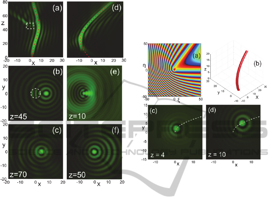
Figure 5: a-c Evolution and transverse amplitude
snapshots at the indicated distances of a beam with a
hyperbolic secant trajectory, in the presence of cylindrical
potential drawn with dashed line with normalized
amplitude 1. d-f Evolution and snapshots of the beam
with the hyperbolic trajectory of Fig. 3b after blocking a
central disk with radius 20 from the input condition.
A characteristic example is shown in Figs. 2d-f
where the hyperbolic beam of Fig. 3d is left to
propagate after blocking a large circular disk from
the center of its input wavefront. We see that even if
initially the beam profile e and trajectory d
are significantly distorted, the wave manages to
recover its structure after covering a healing distance
of around 20 and write the intended hyperbolic
track. Far beyond the healing point f, the beam
has fully recovered its profile and can hardly be
distinguished from the undistorted beam of Fig. 3d.
In a last example, Fig. 6 shows the case of a
beam with a 3D trajectory that varies linearly in the
y and quadratically in the x direction. The path of the
main lobe has been recorded in b. Parts c and d
show how the images of the transverse beam profile
follow the projection of the trajectory on the xy
plane. Beyond this example, the gamut of possibly
interesting trajectories is virtually endless depending
on the optical setting that the beam has to confront.
We have thus managed to go beyond standard
accelerating waves and design Bessel-like optical
beams that can actually self-accelerate along
arbitrary 3D paths.
Figure 6: a Modulo-2π input phase
Q
and b track of
the main lobe in 3D for a beam with trajectory
2
( ( ), ( )) (0.05 ,0.5 ).XzYz z z
c-d Snapshots of the
wave amplitude at different distances. The dashed line is
the projection of the trajectory on the
xy
plane.
4 CONCLUSIONS
We have proposed a method for generating
diffraction-resisting, Bessel-like laser beams capable
of propagating along arbitrary trajectories in free
space. The key idea is to phase-modulate the
wavefront of a standard Gaussian beam so that the
emitted rays are grouped into conical bundles with
expanding circular bases on the input plane that
intersect continuously on a prespecified trajectory.
Our work generalizes previous and more
approximate efforts to manage the trajectories of
Bessel beams along helical and snaking paths by
setting a rigorous analytical framework for the
systematic design of any beam trajectory. We have
shown that, if the radius of these ‘source’ circles is
chosen to be a linear function of the focal distance,
the resulting focus has a distance-independent and
hence diffraction-resistant Bessel function profile.
The method can be used to design an inexhaustible
gamut of trajectories, beyond the fixed parabolic law
of Airy and Airy-related accelerating beams, such as
AdvancedTrajectoryEngineeringofDiffraction-ResistingLaserBeams
17

hyperbolas, general power laws, hyperbolic
functions or even piecewise functions. We have
demonstrated the feasibility of our method through
several numerical simulations of paraxial optical
beams. Such optical beams can be considered as
advanced hybrids between nonaccelerating and
accelerating diffractionless waves and, for that
reason, can find extensive applications in optical
tweezing, testing and microfabrication. Moreover,
they can operate as curved photophoretic optical
traps, capable of guiding particles around
obstructions and exerting forces that are tunable in
3D.
ACKNOWLEDGEMENTS
This work was supported by the FP7-REGPOT-
2009-1 project
“Archimedes Center for Modeling,
Analysis and Computation
” (ACMAC) and by an
“ARISTEIA” Action of the “Operational
Programme Education and Lifelong Learning” that
is co-funded by the European Social Fund (ESF) and
National Resources.
REFERENCES
Andrews, D. L. (2008). Structured Light and Its
Applications. Academic Press.
Arlt, J. and Dholakia, K. (2000). Generation of High-
Order Bessel Beams by use of an Axicon. Opt.
Comm., 177, 297-301.
Bandres, M. 2008. Accelerating Parabolic Beams. Opt.
Lett., 33, 1678-1680.
Bandres, M. 2009. Accelerating Beams. Opt. Lett., 34,
3791-3793.
Bandres, M., Gutiérrez-Vega, J. and Chávez-Cerda, S.
2004. Parabolic Nondiffracting Optical Wave Fields.
Opt. Lett. 29, 44-46.
Berry, M. and Balazs, N. 1979. Non-spreading Wave
Packets. Am. J. Phys., 47, 264-267.
Christodoulides, D. 2008. Optical Trapping: Riding
along an Airy Beam. Nat. Photon., 2, 652-653.
Durnin, J. 1987. Exact Solutions for Nondiffracting
Beams. I. The scalar theory. J. Opt. Soc. Am. A, 4,
651.
Durnin, J., Miceli, J., Eberly, J. (1987). Diffraction-free
Beams. Phys. Rev. Lett., 58, 1499-1501.
Efremidis, N., and Christodoulides, D. 2010. Abruptly
Autofocusing Waves, Opt. Lett. 35, 4045-4047.
Garces-Chavez, V., McGloin, D., Melville, H., Sibbett,
W., and Dholakia, K. (2002). Simultaneous
Micromanipulation in Multiple Planes using a Self-
Reconstructing Light Beam,” Nature, 419, 145-147.
Grier, D. G. (2003). A Revolution in Optical
Manipulation. Nature, 424, 810-816.
Gutiérrez-Vega, J., Iturbe-Castillo, M. and Chávez-Cerda,
S. 2000. Alternative Formulation for Invariant
Optical Fields: Mathieu Beams. Opt. Lett., 25, 1493-
1495.
Herman, R. and Wiggins, T. 1991. Production and Uses
of Diffractionless Beams. J. Opt. Soc. Am. A, 8, 932-
942.
Hu, Y., Zhang, P., Lou, C., Huang, S., Xu, J. and Chen, Z.
2010. Optimal Control of the Ballistic Motion of
Airy Beams. Opt. Lett., 35, 2260-2262.
Jarutis, V., Matijosius, A., Di Trapani, P. and Piskarskas,
A. 2009. Spiraling Zero-Order Bessel Beam. Opt.
Lett., 34, 2129-2131.
Mathis, A., Courvoisier, F., Froehly, L., Furfaro, L.,
Jacquot, M., Lacourt, P.A., Dudley, J.M. 2012
.
Micromachining along a Curve: Femtosecond Laser
Micromachining of Curved Profiles in Diamond and
Silicon using Accelerating Beams. Appl. Phys. Lett.,
101, art. no. 071110.
Matijosius, A., Jarutis, V. and Piskarskas, A. (2010
Generation and Control of the Spiraling Zero-Order
Bessel Beam. Opt. Express, 18, 8767-8771.
McGloin, D. and Dholakia, K. 2005. Bessel Beams:
Diffraction in a New Light. Contemp. Phys., 46, 15-
28.
Morris, J. E., Čižmár, T., Dalgarno, H.I.R., Marchington,
R.F., Gunn-Moore, F. J., and Dholakia, K. 2010.
Realization of Curved Bessel Beams: Propagation
around Obstructions. J. Opt., 12, 124002.
Polynkin, P., Kolesik, M., Moloney, J., Siviloglou, G.,
Christodoulides, D. 2009. Curved Plasma Channel
Generation using Ultra-Intense Airy Beams. Science,
324, 229-232.
Salandrino, A. and Christodoulides, D. 2010. Airy
Plasmon: A Nondiffracting Surface Wave. Opt. Lett.,
35, 2082-2084.
Siviloglou, G. and Christodoulides, D. 2007.
Accelerating Finite Energy Airy Beams. Opt. Lett., 32,
979-981.
Siviloglou, G., Broky, J., Dogariu, A. and Christodoulides,
D. 2007. Observation of Accelerating Airy Beams.
Phys. Rev. Lett., 99, 213901.
PHOTOPTICS2013-InternationalConferenceonPhotonics,OpticsandLaserTechnology
18
