
Optimizing QoS in Wireless Sensors Networks using a Caching Platform
R
´
emy L
´
eone
1
, Paolo Medagliani
2
and J
´
er
´
emie Leguay
2
1
UPMC, 4 Place Jussieu, Paris, France
2
Thales Communications & Security, 4 Avenue des Louvresses, Gennevilliers Cedex, France
Keywords:
Wireless Sensor Networks, Contiki, CoAP, Service Oriented Architecture, Embedded Web Services, Network
Architecture, Internetworking.
Abstract:
This paper addresses monitoring and surveillance applications using Wireless Sensors Networks (WSNs). In
this context, several remote clients are interested in receiving the information collected by the nodes of a WSN.
As WSN devices are most of the time constrained in energy and processing, we present a caching architecture
that will help reducing unnecessary communications and adapting the network to application needs. Our aim
here is to cache information in order to improve the overall network lifetime, while meeting requirements of
external applications in terms information freshness. We first describe and evaluate the performance of our
caching system using a Constrained Application Protocol (CoAP)-HTTP proxy. We then extend this work
by showing how the cache could be enriched and exploited using cross-layer data. Based on information
from routing packets and estimations of nodes power consumption, we derive an optimization strategy which
allows to either maximize the user satisfaction, expressed in terms of freshness of cached data, in the presence
of constraints on network lifetime, or jointly maximize network lifetime and user satisfaction, obtaining a set
of non-dominated Pareto optimal solutions.
1 INTRODUCTION
Sensors are an interface between a physical phe-
nomenon of interest and a numerical information
world (Kovatsch et al., 2012). Recent developments
in technology have brought to the use of Wireless
Sensor Networks (WSNs) in the Internet of Things
(IoT), a new vision of the Internet aiming at push-
ing IP connectivity into smart objects. Nodes inside
a WSN are typically low-power and low-processing
constrained devices. The networks formed using
these devices are commonly referred to as Low-power
and Lossy-Networks (LLNs). Due to the typical ap-
plication fields of a WSN, such as road tunnel fire
monitoring, intrusion detection, wildlife monitoring
and surveillance scenarios, devices are required to op-
erate for long periods of time, for instance decades,
without human intervention, thus the need for high
energy efficiency and self configuring capabilities.
WSNs are proving to be one of the most interesting
innovation in logistic, environment and military tech-
nologies (Akyildiz et al., 2002). Due to their con-
strained nature, it is necessary to introduce optimiza-
tion and self-configuring strategies to increase their
efficiency and autonomy.
First, in this paper we present an architecture for
caching data collected from a WSN. When a request
from a remote client arrives to the caching node, if it
has already a stored value which is “fresh” enough,
it replies to the remote client without forwarding the
request inside the WSN. This paper presents an im-
plementation and the evaluation of this caching so-
lution within a framework running the Constrained
Application Protocol (CoAP) protocol. Relying on
CouchDB to store data, our caching system runs on
the gateway node of a WSN and it is coupled with
Californium, a REST proxy for CoAP. To the best
of our knowledge, this is the first paper presenting a
working HTTP-CoAP proxy and evaluating the im-
pact of CoAP caching on energy consumption in a
WSN.
Then, we extend this work by showing how the
caching mechanism could be enriched with cross-
layer data and exploited to reach energy optimization.
Relying on the routing tree created by the RPL pro-
tocol and on a simple analytical model describing the
energy consumption of the WSN nodes, we will de-
rive an optimization strategy which allows to either
meet a given network lifetime while satisfying Qual-
ity of Service (QoS) on the freshness of the cached
values or jointly maximize QoS and network lifetime.
The remainder of this paper is structured as fol-
23
Léone R., Medagliani P. and Leguay J..
Optimizing QoS in Wireless Sensors Networks using a Caching Platform.
DOI: 10.5220/0004314400230032
In Proceedings of the 2nd International Conference on Sensor Networks (SENSORNETS-2013), pages 23-32
ISBN: 978-989-8565-45-7
Copyright
c
2013 SCITEPRESS (Science and Technology Publications, Lda.)

lows: In Section 2, we present a list of related works.
In Section 3, we introduce the main WSN protocols
we will consider in this paper. Then, in Section 4
we describe the caching architecture we have imple-
mented and we show the performance improvements
given to the use of the caching. In Section 5, we
present the energy model and the cross-layer multi-
objective optimization strategy. Finally, Section 6
concludes this paper.
2 RELATED WORK
IETF drafts from CoRE working group are the foun-
dations of the recent innovation in CoAP application
layer protocols(Shelby, 2012). Software and architec-
ture used in this paper and in most of academic publi-
cations are built on top of these specifications.
Gather information and send it to a single remote
user is not enough. In an IoT perspective, this infor-
mation has to be made easily and immediately avail-
able to several clients without any further operation.
Web service is a solution to achieve this. Several pa-
pers have been published to relate a Service Oriented
Architecture (SOA) and WSNs in order to create Web
Services. The first paper related to this perspective
was (Delicato et al., 2003), where the authors intro-
duced the concept of connection between a WSN and
the Internet. In (Leguay et al., 2008), instead the au-
thors presented a SOA architecture adapted to energy
constrained devices.
Connecting a WSN with web applications has
been explored and several works such as (Kuladinithi
et al., 2011; ?; ?) introduce an architecture to bridge
a WSN to the web. The main point of these works
is to present a reliable architecture that implemented
a basic HTTP/CoAP (HC) gateway without proxying
functionalities.
The use of in-network caching in WSNs in order
to avoid redundant transmission is a known technique
for efficient time and energy saving. In (Duquennoy
et al., 2011), this mechanism is adopted to improve
the performance of software updates in incrementally
deployed sensor networks
In this paper, leveraging on a simple yet effective
HC proxy architecture with caching capabilities, we
implement a lifetime optimization strategy, which ex-
ploits cross-layering techniques to meet requirements
on overall network lifetime, given some constraints
on the freshness of cached information.
3 PRELIMINARIES ON
WIRELESS SENSOR
NETWORKS
Traditional operating systems and Internet protocols
are not suited for operating with WSN devices. In or-
der to meet the typical strong requirements of WSNs
in terms of energy consumption, it is preferable to
let the nodes sleep for an as long as possible, wak-
ing them up only when a packet needs to be transmit-
ted. The basic mechanism proposed in Contiki OS, an
operating system for low-power devices, is the Con-
tiki MAC (Dunkels, 2011). The nodes remain sleep-
ing, that is with radio interfaces switched off) for the
largest part of the duty cycle. When a node needs
to transmit a message, it starts cyclically sending the
packet as soon as the receiving node acknowledges
the reception of the packet. During two consecutive
packet transmission attempts, the transmitting node
waits for a short time interval in order to detect an
eventual incoming acknowledgment packet.
Traditional IPv6 routing protocols are not de-
signed with unstable and intermitting communication
links in mind. Therefore, the IETF ROLL Work-
ing Group has defined an IPv6 Routing Protocol for
Low power and lossy networks (RPL) optimized to
deal with multipoint-to-point traffic, as well as point-
to-multipoint traffic and point-to-point traffic (Winter
et al., 2012). RPL allows the creation of a tree to
transfer information to (or from) a root from (or to)
the remote nodes. The node which has knowledge of
the structure of the tree is the border router.
RESTful web services and the HTTP protocol are
widely used to publish the status of resources (Ko-
vatsch et al., 2012). However, web services are not
suited for constrained networks due to the exaggerate
overhead introduced by HTTP and the presence of the
TCP congestion window. For these reasons, the CoRE
IETF working group aims at realizing the REST ar-
chitecture in a suitable form for LLNs through the
definition of a protocol referred to as Constrained Ap-
plication Protocol (CoAP) (Shelby, 2012).
When a HTTP client wants to receive the status of
a resource running CoAP, the HTTP request must be
translated into a CoAP request (and vice versa for the
response). Normally, the protocol translation is car-
ried out by a HC proxy. Unlike HTTP, CoAP requests
and responses are not sent over a previously estab-
lished connection. In fact, whilst HTTP is based on
the TCP transport protocol, CoAP is based on UDP,
which introduces less overhead and has no need for
session maintenance. In order to reduce response
time and network bandwidth consumption, the CoAP
servers or end-points may cache responses.
SENSORNETS2013-2ndInternationalConferenceonSensorNetworks
24

4 THE CACHING MODEL
In this section we will describe the caching mecha-
nism implementation and we will a simple analytical
model which well approximates the performance in
terms of requests served by the caching platform.
4.1 Justification
One of the main reasons to develop a caching archi-
tecture for WSNs is to let sensors save energy by han-
dling in the caching node the information that has
already been requested by a remote client. In this
way the WSN devices can continue to stay in a sleep
state since remote requests are directly served by the
caching node.
1
In addition, exploiting suitable opti-
mization strategies and cross-layering techniques, we
can also use the information stored in the cache in or-
der to compute route optimization and graceful degra-
dation on the QoS of the WSN, in order to meet a
given overall network lifetime.
According to the CoAP protocol, the goal of the
cache is to reuse a previously stored, if recent enough,
response to satisfy a client request, reducing energy
consumption in the WSN. If the collected value is
older than a given threshold parameter, then a request
to the resource is performed. Otherwise, the value
stored in the cache is directly sent back to the client.
According to the protocol drafts and recommenda-
tions (Shelby, 2012; ?), how the proxy actually sat-
isfies the request is an implementation choice. How-
ever, we can assume several scenarios where the bor-
der router/proxy may be resource constrained. There-
fore, in some cases this solution may not be appro-
priate and one could prefer to avoid the use of such a
proxy, falling back to an end-to-end CoAP communi-
cation.
4.2 The Caching System Architecture
The caching system has been implemented relying on
the IETF protocols. We made this choice both be-
cause some libraries, which can be reused to speed
up the implementation, are already available and be-
cause IETF protocols have been specifically designed
to meet the constraints typical of IoT architectures.
In order to test and validate the performance of our
caching architecture, we have chosen Contiki OS,
since it provides for a simulation environment like
Cooja and implementations of the RPL and CoAP
protocols. As one of the goal of this paper is energy
1
We remark that power consumption in sleep state is or-
ders of magnitude lower than those in reception and trans-
mission states.
CoAP servers
Border
router
CoAP HTTP
Cache
CoAP
router
RPL
root
Pub/sub
register
HC proxy
Figure 1: Scheme of the implemented caching system.
saving inside the WSN, we have decided to use Con-
tikiMac MAC protocol, which provides for duty cycle
capabilities and it has been optimized to not occupy
too much RAM memory with its footprint. In ad-
dition, implementations of CoAP and RPL protocols
are already available in Contiki OS, thus allowing us
to quickly have a working and running testbed.
In Figure 1, we show a logical scheme of the im-
plemented caching system, where N CoAP servers ex-
pose one resource to be queried. The running routing
protocol is RPL. All the requested information and
the notifications from the nodes are gathered to the
root of the RPL tree, which overlaps with the WSN
gateway. The HC proxy will then send to the final
user the requested information.
Our HC proxy implementation is based on the
Californium open source framework (Kovatsch et al.,
2012). The main reason of this choice is that Cal-
ifornium already implements in JAVA a basic set of
CoAP functionalities. We have then introduced two
information storing mechanisms. The first one is the
caching database, where all the information from the
WSN are gathered and stocked and for which we have
chosen CouchDB, since it offers a REST HTTP API
to query stored results. The second one is a subscrip-
tions register to efficiently manage the subscribers to
the CoAP resources.
The arrival rate of each request made by a remote
user to the i-th resource is distributed as a Poisson pro-
cess of parameter λ
i
(dimension: [s
−1
]). The requests
are intercepted by the HC proxy which handles also
the eventual response from the given CoAP server. If
the proxy has a stored value which is fresh enough,
that is whose lifetime is smaller than a given value c
i
(as explained below), it directly replies to the request
from a remote client, without forwarding it into the
WSN. Otherwise, if the required value is not present
or it is older than c
i
, it transfers the request to the i-
th CoAP server. Additionally, the proxy stores the
sensor responses in the cache, in order to make them
available for other eventual incoming requests.
A similar approach is used for the publish-
subscribe register. In the case of observation requests
issued by a remote client, the proxy handles them by
maintaining a list of observed resources and a list of
OptimizingQoSinWirelessSensorsNetworksusingaCachingPlatform
25

root b
d
f
h
c
j
e
k
g
l
i
m
1 hop
2 hops
3 hops
Figure 2: The considered network topology. N = 12 nodes
(depicted as octagons) are placed in a regular grid with the
root (round node) in the middle. The number of lines of the
contour of each octagon refers to the distance, in terms of
hops, from the root.
interested clients. Each time a notification for a re-
source update is sent from the node to the proxy, the
proxy will forward this messages to all the interested
subscribers.
Caching and observe mechanisms can operate to-
gether as well. For instance, an information already
requested by an observe request can be cached and
made available to another request not related to the
previous observation. In fact, the caching and the
observation mechanism are independent from each
other. Nevertheless, the two system should be used
together because information obtained by observation
can help the caching operations.
4.3 Experimental Validation of the
Caching Architecture
4.3.1 Experimental Setup
In order to evaluate the previously described caching
model, we introduce the following simulation setup.
A grid of N = 12 Contiki nodes running CoAP server
is deployed. These Contiki-CoAP nodes are emulated
using COOJA. Due to limitations of Contiki tools to
obtain and analyze the energy consumption, we have
preferred using the number of requests served by the
HC proxy as a metric to measure of saved energy. In
order to have a small memory footprint, each of the
CoAP server will only have a single resource and this
resource will be a fixed text message. An illustrative
example of the considered topology is depicted in Fig-
ure 2. According to the scheme shown in Figure 1, a
remote client first randomly chooses one of the CoAP
servers and then issues to it a GET request for know-
ing the status of the selected resource. The interarrival
time between two consecutive requests is distributed
according to an exponential distribution of parame-
ter λ.
2
Since the requests for the CoAP resources are
equiprobable, exploiting the superposition propriety
of the Poisson processes, we can say that the arrival
rate of the requests for each node is still a Poisson dis-
tribution of parameter λ
i
= λ/N, where i denotes the
resource on the i-th node, therefore the arrival rate of
the requests for a generic i-th node is a Poisson pro-
cess of parameter λ
i
.
The requests from the remote client are inter-
cepted by the HC proxy, which translates HTTP re-
quests into CoAP requests and, conversely, translates
the CoAP responses into HTTP responses. In addi-
tion, the proxy caches the responses carried out by
the CoAP nodes in order to make them available for
eventual other incoming request. The freshness of the
cached value for the i-th node is denoted as c
i
. If a
request for the status of the i-th resource arrives, the
proxy first verifies in the cache if it already has an
available value to be sent back to the client, that is a
value whose lifetime is smaller than c
i
, otherwise it
forwards the request to the WSN node to obtain an
updated response. Additionally, the HC proxy stores
the collected value in the cache for future requests and
forward the collected information to the final client.
Like in every caching system, refresh parameters are
highly critical. If c
i
is too large, information won’t
be sufficiently renewed and cached values may often
be different from the real values. If c
i
is too small,
then the proxy will be underperforming, wasting en-
ergy and not reaching the optimal performance.
The simulations have been carried out generat-
ing 50 requests from the remote client to the CoAP
servers in the WSN. In order to bound possible statis-
tical fluctuations in the simulation results, the simula-
tion results are obtained by averaging over 10 consec-
utive runs.
The main parameters of the overall system model
are listed in Table 1. The power consumption pa-
rameters presented in this table have been taken from
the internal data-sheet of a prototype sensor node by
Thales. Like other well-known commercial sensor
nodes using the CC2420 chipcon (e.g., Crossbow Mi-
caZ, Berkeley Telos (Polastre et al., 2005)), power
consumption is higher in the reception mode than in
the full-power transmission mode.
In order to simplify the simulations, we have con-
sidered the same values of λ
i
, c
i
, and the same duty
cycle for each CoAP node in the WSN.
2
We remark that is λ is the arrival rate of the requests to
the HC proxy.
SENSORNETS2013-2ndInternationalConferenceonSensorNetworks
26

Table 1: System parameters considered in the simulations.
Node transmission rate R 250 kbps
Interval between two consecutive strobed preambles T
p
0.4 ms
Time to detect an incoming Ack packet T
d
0.16 ms
GET packet length L
GET
87 bytes
Response packet length L
Ans
96 bytes
Ack transmission duration S
Ack
0.608 ms
Transmission power consumption P
Tx
0.0511 W
Reception power consumption P
Rx
0.0588 W
Sleep power consumption P
sleep
2.4 · 10
−7
W
Number of nodes in the network N 12
4.3.2 Analytical Model of the Caching
Architecture
The mechanism of caching can be summarized as fol-
lows: a client issue a request to one of the nodes in the
network. This means that if the proxy doesn’t have an
updated replica of the required value, it transfers the
request to the WSN, caching the response for eventual
other requests to the same resource. The interarrival
time T
i
(dimension: [s]) between two consecutive re-
quests can be modeled as an exponentially distributed
random variable of parameter λ
i
. Since in our simu-
lation the destination of the request is randomly cho-
sen, on average, we can say that we must wait for N
consecutive requests before having a new request on
the same node i. Therefore, assuming that λ
i
is the
same for all the N nodes in the network, the time in-
terval between the different requests to the same node
is distributed with an exponential law of parameter
T = NT
i
= N/λ
i
.
The cache miss ratio (MR) can be defined as the
probability that a request is not served by the caching
architecture. Therefore, MR corresponds to the prob-
ability that the interarrival time between two consec-
utive requests to the same node is larger than c
i
, that
is
MR =
Z
∞
c
i
e
−
t
T
T
dt = e
−
c
i
T
. (1)
Therefore, the cache hit ratio (CH) can be expressed
as the complementary of MR, that is
CH = 1 − e
−
c
i
T
. (2)
According to the scheme depicted in Figure 1, the
remote clients send a resource observation request to
one of the N randomly chosen CoAP servers. The
request arrival rate is distributed according to a Pois-
son distribution of parameter λ
i
, where i denotes the
node to which the request is directed. As explained
in the previous subsection, for every observation it is
possible to define a freshness parameter c
i
, that is for
how long the collected data is valid before the data is
discarded by the proxy and a new data request must
be issued to the CoAP server.
3
In truth, as explained
later, for every observed value we can define a min-
imum and a maximum admittable freshness values,
denoted as c
i
min
and c
i
max
respectively.
If the resource required by the remote client is not
in the cache or the cached value is outdated, the proxy
issues a CoAP request to the given CoAP server.
Given that a request for the i-th node arrives, on aver-
age, every T
i
s, it can be proved that the average period
r
i
(dimension: [s]) between two consecutive requests
to the same node can be defined as:
r
i
=
d
c
i
T
i
eT
i
if T
i
≤ c
i
T
i
else.
(3)
In the following subsection, we will provide the per-
formance of the caching system in terms of cache hit
ratio and network lifetime.
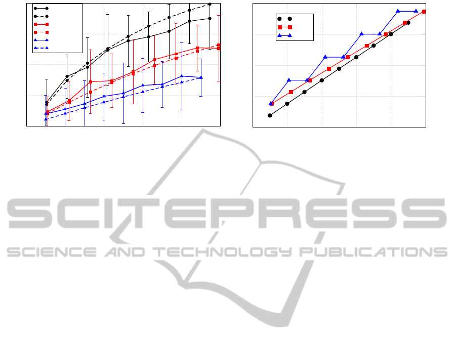
4.3.3 Performance Validation of the Caching
Architecture
In order to evaluate the performance of the imple-
mented caching system, we first evaluate the cache
hit ratio CH as a function of the freshness parame-
ter c
i
. We indicate, for each performance curve, the
confidence interval 2σ, where σ is the standard devia-
tion, over consecutive simulation runs, with respect to
their average value. In Figure 3 (a), the results are de-
picted. Both simulation (solid lines) and theoretical
(dashed lines) results ares shown considering differ-
ent values of the parameters λ
i
. Of course, the higher
the value of λ
i
, the higher the number of requests per
unit of time. All the curves shown in Figure 3 (a)
are growing when the cache duration parameter in-
creases. Clearly, the larger the cache duration, the
3
In our derivation, we assume that each node has only
one available CoAP resource, therefore the freshness of the
i-th observed value corresponds to the freshness of the i-th
node.
OptimizingQoSinWirelessSensorsNetworksusingaCachingPlatform
27
0 2 4
6
8 10
c
i
[s]
0.0
0.2
0.4
0.6
0.8
CH
λ
i
= 2, sim.
λ
i
= 2, theo.
λ
i
= 1, sim.
λ
i
= 1, theo.
λ
i
= 0.5, sim.
λ
i
= 0.5, theo.
0 2 4
6
8 10
c
i
[s]
0
30
60
90
120
Lifetime [days]
λ
i
= 2
λ
i
= 1
λ
i
= 0.5
(a) (b)
Figure 3: (a) CH as a function of the cache freshness c
i
. Simulation (solid lines) and theoretical (dashed lines) results are
presented. (b) Network lifetime as a function of the cache freshness c
i
. In both cases, different values of λ
i
have been
considered: λ
i
= 2 (lines with circles), λ
i
= 1 (lines with squares), and λ
i
= 0.5 (lines with triangles).
higher the probability that the request is served by the
proxy, not being forwarded to the WSN nodes. Sim-
ilarly, for a given value of cache duration, the higher
the number of arrival per unit of time, the higher the
probability that the proxy replies to the client with
a cached value. The beneficial effect of the use of
caching is not limited only to the energy saving re-
lated to the lower number of packets transferred to the
WSN with the use of proxy. When the traffic is high,
in fact, it becomes more and more likely that a cached
value may serve several requests from some remote
clients. Therefore, the introduction of a caching sys-
tem allows to reduce the requests transferred to the
WSN and, consequently to significantly reduce packet
retransmissions or losses.
The use of a caching system also allows to save
energy and extend the network lifetime, defined as the
time required to the network to have at least one node
running out of energy. In Figure 3 (b) we can see the
impact of caching on the lifetime of our system. As
the intuition may suggest, the larger c
i
, the larger the
network lifetime, since a larger number of requests
are served by the cache without being transferred to
the WSN. The “stair” behavior of the curve with λ
i
=
0.5 is due to the fact that, according to the definition of
r
i
in (3), different values of c
i
lead to the same number
of requests transferred to the WSN.
5 ADVANCED CACHE
EXPLOITATION
5.1 Parameters of the Optimization
Framework
The choice of the optimal caching lifetime is appli-
cation dependent. According to the energy level of
a node, we can decide to increase the lifetime of the
cached values, accepting less updated values but, on
the other side, extending the network lifetime, due
to the reduced number of requests transferred to the
WSN.
In order to derive an optimization framework, we
must rely on the hypothesis that the WSN nodes are
static and the quality of the communication links are
fair enough to consider the transmissions as error free,
so no energy is wasted for packet retransmissions. We
also assume that no transmission phase locking mech-
anism has been used at the MAC layer. We need to in-
troduce some parameters to describe the optimization
framework within the caching architecture:
• c
i
min
and c
i
max
are the lower and upper bounds, re-
spectively, of the amount of time that a requested
information can live in the cache. It’s useless to
request an information that is fresher than c
i
min
.
Similarly, an information older than c
i
max
is not
meaningful anymore.
• c
i
is the cache lifetime of the i-th resource, with
c
i
∈ [c
i
min
;c
i
max
]. This information can be changed
according to the current state of our system in or-
der to fulfill our optimization goals. When an
updated information is needed, the c
i
parameter
can be set to 0, so that the caching node becomes
transparent.
It is necessary to define some metrics of interest
in order to characterize the optimization strategy in-
troduced in this paper. First of all, we define the net-
work lifetime as the time interval between the net-
work start-up and the first node running out of en-
ergy. In our approach, we consider, as a metric of
user satisfaction, the freshness c
i
of the values stored
in the cache, that is, the shorter the cache duration,
SENSORNETS2013-2ndInternationalConferenceonSensorNetworks
28

the higher the user satisfaction. Of course, referring
to the results presented in Figure 3 (a), when the du-
ration of the cached values is small, it is likely that
an incoming request is transferred to the WSN, thus
resulting in energy consumption and reduction of the
network lifetime. On the other side, the maximization
of the network lifetime requires to minimize the trans-
missions inside the WSN, that is to keep the duration
of the cached values as elevated as possible. The user
satisfaction for the i-th resource can be then defined
as
γ
i
=
c
i
max
− c
i
c
i
max
− c
i
min
∗ 100, (4)
that is a user satisfaction of 0% when c
i
= c
i
max
and a
user satisfaction of 100% when c
i
= c
i
min
.
5.2 Energy Model of the Cached WSN
In order to describe the energy consumption associ-
ated to the collection of resources, we assume that the
impact of RPL messages is neglectable. Roughly, we
can say that the energy consumption of each node is
given by the sum of the energy consumptions of its
hardware components. For the sake of simplicity, we
only integrate in the energy model contributions from
the communication sub-unit (radio transceiver). The
network lifetime is defined as the time needed for the
average residual energy E
r
to be lower than a (given)
threshold value E
th
, which can be used to model the
physical behavior of a node. The residual energy of
node i at time t, denoted as E
r
i
(t), can be expressed as
E
r
i
(t) = E
0
i
− Ω
tot
i
t (5)
where E
0
i
is the initial energy of the i-th node and
Ω
tot
i
(dimension: [W]) is the power consumption as-
sociated to its communication operations. For the
sake of simplicity, we assume that all nodes have
the same initial energy. According to the descrip-
tions of the Contiki MAC protocol in Section 3 and
in (Dunkels, 2011), there are four possible states for
a node: (i) transmission, (ii) reception, (iii) sleep,
and (iv) channel listening, with corresponding power
consumptions denoted as Ω
T
i
, Ω
R
i
, Ω
S
i
, and Ω
CL
i
(dimension:[W]), respectively. Before starting the
derivation we need to define the period T
MAC
i
as the
time interval between two subsequent active phases
of the i-th node, and T
sleep
i
as the duration of the sleep
phase of the i-th node.
4
The Ω
tot
i
in (5) can be ex-
pressed as follows:
Ω
tot
i
= Ω
S
i
+ Ω
CL
i
+ Ω
T
i
+ Ω
R
i
(6)
4
The duration of the active phase T
act
i
can be evaluated
as T
act
i
= T
MAC
i
− T
sleep
i
.
where: Ω
S
i
is the power consumption associated with
the sleep phase of the i-th node; Ω
CL
i
is the power
required when performing the channel listening op-
erations (over a period of duration T
MAC
); Ω
R
i
is the
power used by a node to receive a packet; Ω
T
i
is the
power used to transmit an alert packet.
According to the RPL protocol, there are three
kinds of nodes: (i) the CoAP servers, (ii) the routers,
acting also as CoAP servers, and (iii) the root of the
tree. Since the length of the GET messages and the
observed values are different in length, we will dis-
tinguish between the time interval required to trans-
mit/receive a GET packet, defined as S
GET
= L
GET
/R,
and the time required to transmit/receive the response
from a CoAP server, defined as S
Ans
= L
Ans
/R, where
L
GET
and L
Ans
are the packet lengths of the GET
packet and the observation packet, respectively, and
R is the transmission rate of the nodes. According to
the Contiki MAC protocol, as described in (Dunkels,
2011) when a node needs to transmit a packet, it must
be for a period of time S
pck−Tx
Tx
in transmission and
for a period of time S
pck−Tx
Rx
in reception, in order
to receive the acknowledgment (ACK) message from
the receiving node. This period of time spent in trans-
mission of the packet can be expressed as
S
pck−Tx
Tx
=
3 + b
T
sleep
i
−S
pck
S
pck
c
2
S
pck
(7)
whereas the period of time spent in reception during
the transmission phase can be expressed as
S
pck−Tx
Rx
=
3 + b
T
sleep
i
−S
pck
S
pck
c
2
T
d
+ S
ack
(8)
where S
pck
indicates a generic transmitted packet (it
must be replaced with S
GET
or S
Ans
depending on
whether the node is transmitting a GET or a response
packet), T
d
is the time required to successfully de-
tect an acknowledgment from the receiver, and S
ack
is the time required to transmit an ACK. Equation
(7) has been derived averaging between the best case
of packet transmission, that is the node starts trans-
mitting when the receiving node is waken up, and the
worst case, that is the receiving node has just switched
into the sleep phase when the transmitting node be-
gins sending the packet. Similarly, when a node needs
to receive a packet, it spends a part of the time in re-
ception and a part of the time in transmission since
it has to send the ACK to the transmitting node. The
period of time spent receiving the packet can be ex-
pressed as
S
pck−Rx
Rx
=
3S
pck
2
+ T
p
(9)
OptimizingQoSinWirelessSensorsNetworksusingaCachingPlatform
29

whereas the period of time spent in transmission dur-
ing the reception phase can be expressed as
S
pck−Rx
Tx
= S
ACK
(10)
where T
p
is the interval between each packet trans-
mission and S
ACK
is the duration of the transmission
of an ACK message. We point out that equation (9)
has been obtained averaging the energy consumption
between the best, that is the receiving node needs to
receive only the packet once, and the worst case of
packet arrival, that is the receiving node wakes up just
after the beginning of the transmission of the packet
by the transmitting node, so it has to wait for the next
packet transmission to correctly receive it.
According to the different nodes allowed by the
CoAP protocol, the terms Ω
T
i
and Ω
R
i
will be dif-
ferent for a CoAP server, a router, and the root of
the tree. In the first case, the terms will be replaced
by Ω
CoAP−T
i
and Ω
CoAP−R
i
, in the second case the
terms will be replaced by Ω
Router−T
i
and Ω
Router−R
i
,
whereas in the third the terms will be replaced by
Ω
root−T
i
and Ω
root−R
i
. Considering a generic CoAP
server without routing functionalities, which only re-
ceives a GET message and transmits the observed
value, the power consumption during the transmission
phase can be expressed as
Ω
CoAP−T
i
=
P
Tx
S
Ans−Tx
Tx
+ P
Rx
S
Ans−Tx
Rx
r
i
(11)
whereas the power consumption during the reception
phase can be expressed as
Ω
CoAP−R
i
=
P
Rx
S
GET−Rx
Rx
+ P
Tx
S
GET−Rx
Tx
r
i
(12)
replacing the packet lengths of the GET message and
of its related response into equations (7), (8), (9),
and (10). The terms P
Tx
and P
Rx
denotes the power
consumptions of a node in transmission and recep-
tion phase. Considering the root node of the network,
instead, the power consumptions to transmit a GET
message to a generic node i and receive back its re-
sponse can be expressed as
Ω
root−T
i
=
P
Tx
S
GET−Tx
Tx
+ P
Rx
S
GET−Tx
Rx
r
i
and
Ω
root−R
i
=
P
Rx
S
Ans−Rx
Rx
+ P
Tx
S
Ans−Rx
Tx
r
i
,
respectively. Since the root transmits to each of the N
associated children, the power consumption to trans-
mit to all the nodes and to receive a packet from all
the nodes can be expressed as
Ω
root−T
=
N
∑
i=1
Ω
root−T
i
(13)
and
Ω
root−R
=
N
∑
i=1
Ω
root−R
i
, (14)
respectively. Considering the intermediate routing
nodes, since they are in charge of transferring both the
request from the root to the CoAP servers and the re-
sponses from the CoAP servers to the root, we can say
that they act both as root for the children nodes and as
CoAP servers for the root. Therefore, the power con-
sumptions to forward the incoming packets can be ex-
pressed as
Ω
Router−T
i
=
∑
j∈m
i
Ω
CoAP−T
j
+ Ω
root−T
j
+ Ω
CoAP−T
i
(15)
and
Ω
Router−R
i
=
∑
j∈m
i
Ω
CoAP−R
j
+ Ω
root−R
j
+Ω
CoAP−R
i
,
(16)
where m
i
, as shown in Figure 1, denotes the number of
children associated to the i-th node. The terms at the
right-hand side of (15) and (16) have been introduced
since these nodes, besides acting as routers, may also
behave as CoAP servers.
Finally, the power consumption in the channel lis-
tening state can be expressed as
Ω
CL
i
=
T
act
P
Rx
T
MAC
, (17)
whereas the power consumption in the sleep phase
can be denoted as
Ω
S
i
=
T
sleep
i
P
Sleep
T
MAC
− Γ
Tx
i
− Γ
Rx
i
, (18)
where P
Sleep
is the power consumed in the sleep state,
and Γ
Tx
i
and Γ
Rx
i
are two corrective terms, described
in more detail below. During normal operations the
node either performs channel listening and sleep op-
erations or transmits/receives a packet. Γ
Tx
i
and Γ
Rx
i
are used to refine the power consumption due to sleep
operations. In fact, the sleep and also the transmission
and reception intervals overlap for short intervals, so
that without these two terms the power consumption
budget would be higher than the correct one. In par-
ticular, Γ
Tx
i
can be expressed as
Γ
Tx
i
= Ω
S
i
3 + b
T
sleep
i
−S
pck
S
pck
c
2
(S
pck
+ T
d
) + S
ack
T
MAC
i
(19)
whereas Γ
Rx
i
can be expressed as
Γ
Rx
i
= Ω
S
i
3S
pck
2
+ T
p
+ S
ack
T
MAC
i
(20)
SENSORNETS2013-2ndInternationalConferenceonSensorNetworks
30

The term Γ
Tx
i
takes into account the fact that, during
transmission operations, such as (i) strobed transmis-
sion of the packet over an interval of duration T
sleep
i
,
(ii) packet transmission, and (iii) acknowledgment re-
ception, a node would normally be in the sleep state.
Thus, the correction factor Γ
Tx
i
is necessary, since
otherwise the energy consumed by the node with this
model would be higher than the real value because
reception and transmission operations would overlap
with normal sleep operations for a period. Similar
considerations can be carried out for the term Γ
Rx
i
. In
fact, when a node is waiting for the acknowledgment
window to transmit an ACK message, to receive the
preamble, and to receive a packet, it would normally
be in the sleep state.
Replacing expressions (19) and (20) into (18) and
expressions (11), (12) (if a CoAP node, otherwise
(15) and (16) for a router or (13) and (14) for the
root), (17), and (18) into (6), it is possible to derive
an expression for the energy consumption depending
on topology and communication parameters.
5.3 An Optimization Framework
The above introduced analytical model can be used
during network configuration in order to find the
proper values of c
i
which allow to meet a given re-
quirement on minimum network lifetime. Of course,
as introduced in Subsection 5.1, considering a min-
imum and a maximum value of cache duration, the
best network lifetime can be reached using c
i
= c
i
max
.
On the other side, if we want to maximize the average
user satisfaction γ, defined as γ =
∑
N
i=1
γ
i
/N, we must
set c
i
= c
i
min
, with the opposite undesirable effect that
the lifetime is minimized.
The choice of the suitable values of c
i
introduces
then a trade-off between network lifetime and user
satisfaction. In addition, since some nodes act as
routers, decreasing the number of transmissions to
the i-th node may affect not only the lifetime of
node i, but also the lifetime of the routers which are
on the path between node i and the root. In order
to solve these problems, we use the Non-dominated
Sorting Genetic Algorithm II (NSGA II) (Deb et al.,
2002). Given the minimum target lifetime, the inter-
val [c
i
min
;c
i
max
], and the network topology generated
by the RPL protocol, the solver provides for the best
set of c
i
parameters which satisfies the constraints on
lifetime while maximizing the user satisfaction γ.
Considering a scenario with c
i
min
= 1 s and c
i
max
=
9 s, λ
i
= 1 s
−1
, and the topology with N = 12 nodes
shown in Figure 2, we have set some constraints on
network lifetime, namely at least 25, 50, and 75 days,
and we have evaluated the set of c
i
opt
which maxi-
Table 2: Performance results of the optimization strategy
compared with the cases with c
i
= c
i
min
and c
i
= c
i
max
. For
estimating c
i
opt
, target lifetimes of 25, 50, and 75 days have
been considered.
c
i
lifetime [days] γ
c
i
min
11.4219 100%
c
25
i
opt
25 95%
c
50
i
opt
50 68%
c
75
i
opt
75 49%
c
i
max
101.256 0%
0 20 40
60
80 100
γ [%]
20
40
60
80
100
Lifetime [days]
Pareto front
Figure 4: Pareto front of the considered caching architec-
ture.
mizes the user satisfaction while fulfilling the network
lifetime requirement. As a comparison, we also show
the results obtained without the optimization tool, that
is those obtained with c
i
= c
i
min
and c
i
= c
i
max
. The
results are shown in Table 2. The set of c
i
obtained
through the optimization tool allows to effectively
meet the requirement on network lifetime while max-
imizing the user satisfaction.
If no constraints on lifetime are imposed, finding
a suitable working point (i.e., a suitable set of values
of c
i
) for the system can be seen as a multi-objective
optimization problem. In this case, the NSGA II al-
gorithm allows to find the non-dominated Pareto front
of solutions, that is the set of values which are Pareto
optimal. According to the definition of Pareto op-
timality, a solution is Pareto optimal when it is not
possible to improve one objective without reducing
at least one of the other objectives. In Figure 4, the
Pareto front for the presented caching architecture is
shown. According to the presented results, it is possi-
ble to find out a set of suitable working points which
allows to achieve the best possible network configu-
ration. The solver associates to each of these points a
set of parameters c
i
which can be used at the network
start-up to properly tune the cache duration.
We point out that the above presented optimiza-
tion strategy has been evaluated according to a spe-
OptimizingQoSinWirelessSensorsNetworksusingaCachingPlatform
31

cific definition of QoS. However, it can be easily gen-
eralized in order to encompass other objective func-
tions or other constraints in the optimization process.
6 CONCLUSIONS
This paper has addressed the problem of energy effi-
cient QoS optimization in WSNs using cross-layering
techniques and exploiting a specifically introduced
caching platform. We have first presented the imple-
mentation of a caching solution based on a proxy node
which is in charge of answering, if a cached value is
available, to a request coming from a remote client
without transferring it to the WSN. Simulation results
show that the introduction of a caching architecture
has an impact in terms of energy saving on the system
performance, since it allows to reduce the transmis-
sions inside the WSN. Then, we have introduced an
optimization framework which, exploiting the infor-
mation collected by the RPL protocol and given a set
of constraints on the minimum and maximum values
of cache duration, allows to optimally configure the
values of the caching lifetimes. The proposed opti-
mization strategy allows to either find suitable solu-
tions in the presence of constraints on network life-
time or to find out the optimal non-dominated set of
solutions in the case of multi-objective optimization.
Further works include the real-time change of the
routing paths, in order to save the nodes which are
running out of energy, and large-scale experiments,
using the Senslab platform (Senslab Website, 2008),
in order to get real energy consumption data from
physical nodes.
ACKNOWLEDGEMENTS
This work is funded by the European Community’s
Seventh Framework Programme, area “Internetcon-
nected Objects”, under Grant no. 288879, CALIPSO
project - Connect All IP-based Smart Objects. The
work reflects only the authors’ views; the European
Community is not liable for any use that may be made
of the information contained herein.
REFERENCES
Akyildiz, I., Su, W., Sankarasubramaniam, Y., and Cayirci,
E. (2002). Wireless sensor networks: a survey. Com-
puter networks, 38(4):393–422.
Deb, K., Pratap, A., Agarwal, S., and Meyarivan, T. (2002).
A fast and elitist multiobjective genetic algorithm:
NSGA-II. IEEE Trans. on Evolutionary Computation,
6(2):182–197.
Delicato, F., Pires, P., Pinnez, L., Fernando, L., and
da Costa, L. (2003). A flexible web service based ar-
chitecture for wireless sensor networks. In Distributed
Computing Systems Workshops, 2003. Proceedings.
23rd International Conference on, pages 730–735.
IEEE.
Dunkels, A. (2011). The ContikiMAC Radio Duty Cycling
Protocol. Technical Report T2011:13, Swedish Insti-
tute of Computer Science.
Duquennoy, S., Wirstr
¨
om, N., Tsiftes, N., and Dunkels, A.
(2011). Leveraging IP for Sensor Network Deploy-
ment. In Proc. of the Work. on Extending the Internet
to Low power and Lossy Networks (IP+ SN 2011).
Kovatsch, M., Mayer, S., and Ostermaier, B. (2012). Mov-
ing Application Logic from the Firmware to the
Cloud: Towards the Thin Server Architecture for the
Internet of Things. In Proc of the 6th Int Conf on In-
novative Mobile and Internet Services in Ubiquitous
Computing (IMIS 2012), Palermo, Italy.
Kuladinithi, K., Bergmann, O., P
¨
otsch, T., Becker, M., and
G
¨
org, C. (2011). Implementation of CoAP and its
Application in Transport Logistics. Proc. IP+ SN,
Chicago, IL, USA.
Leguay, J., Lopez-Ramos, M., Jean-Marie, K., and Conan,
V. (2008). An efficient service oriented architecture
for heterogeneous and dynamic wireless sensor net-
works. In Local Computer Networks. LCN 2008. 33rd
IEEE Conf, pages 740–747. IEEE.
Polastre, J., Szewczyk, R., and Culler, D. (2005). Telos: en-
abling ultra-low power wireless research. In Proc. of
the 4th Int. Symp. on Information Processing in Sen-
sor Networks (IPSN 05), pages 364 – 369, Piscataway,
NJ.
Senslab Website (2008). http://www.senslab.info/.
Shelby, Z. (2012). Constrained Application Protocol
(CoAP). Internet-Draft draft-ietf-core-coap-09, Inter-
net Engineering Task Force. Work in progress.
Winter, T., Thubert, P., Brandt, A., Hui, J., Kelsey, R.,
Levis, P., Pister, K., Struik, R., Vasseur, J., and
Alexander, R. (2012). RPL: IPv6 Routing Protocol
for Low-Power and Lossy Networks. RFC 6550 (Pro-
posed Standard).
SENSORNETS2013-2ndInternationalConferenceonSensorNetworks
32
