
Arrangements of Finite-state Machines
Semantics, Simulation, and Model Checking
Vladimir Estivill-Castro and Ren
´
e Hexel
School of ICT, Griffith University, Nathan Campus, 4111 Queensland, Australia
Keywords:
Applications and Software Development, Model-based Testing and Validation, Model Execution and Simula-
tion, Executable UML.
Abstract:
We propose a contrasting approach to the main stream direction that UML and STATEMATE have recently taken
when using finite-state machines (FSMs) to model behaviour. That is, rather than the event-driven model that
is currently dominant, we suggest to adopt a model of time, a synchronous model. We do support concurrency
in our arrangements of FSMs but eliminate the sources of unpredictable threads of execution. Currently,
such capacity of the dominant semantics actually results in the need to create many language constructs to
regulate threads that, in many cases, even result in imprecise semantics, hampering their use for model-driven
development (MDD). By allowing transitions to only be labeled by statements of logic and by executing
the machines with an offline schedule, we obtain a simpler language, with less burden for the developer.
This creates far reaching potential for accompanying tools, such as integrated development environments,
simulators, and even formal verification through model-checking. Model-checking is of particular importance
as MDD becomes ubiquitous. Model-checking is possible for our FSMs as we do not need to consider all
possible combinations of progress of each of the many threads that the event-driven alternative requires.
1 INTRODUCTION
We present a language of arrangements of finite-
state machines (FSMs) that aims at offering sim-
plicity of constructs and high versatility. Thus, this
paper introduces a minimal subset of UML 2 and
Harel’s state charts with two significant characterisa-
tions. The first characterisation is that we adopt the
synchronous model of FSMs as opposed to the asyn-
chronous model (Harel and Naamad, 1996, Section 9,
“Two models of time”). That is, our FSMs are not
waiting in a state to be woken up by the occurrence
of an event. In fact, once an arrangement of FSMs is
present, one step of one of the FSMs is executed in
each time-slot. The other significant characterisation
is that transitions are labeled by queries (and not by
events) to an inference engine. The idea of transitions
labeled by queries (and not by events) can probably
be traced to the XABSL modelling language (L
¨
otzsch
et al., 2004; Risler and von Stryk, 2008) for robots and
agents where transitions are labeled by decision trees.
This combines a declarative model (a model that de-
scribes what the software knows about, what concepts
to use, what things mean), with the action model of
FSMs. Minimality is sought to reduce implementa-
tion complexity, maximise ease of adoption and use,
remove implicit assumptions and provide a clear se-
mantics (several authors (von der Beeck, 1994; Es-
huis, 2009; Breen, 2004; Simons, 2000) discuss the
problems with state charts and as a result, there have
been several revisions even to UML state-charts). In
particular our modelling notation seeks agreement
with UML, SXML (W3C, 2012) and Harel’s state
charts to maximise adoption.
2 FINITE-STATE MACHINES
Our state machines are in close proximity with the
mathematical model of behaviour, the so called finite-
state automata (Hopcroft et al., 1979) that produce
output, also known as transducers. That is, our FSMs
consist of a set S of states, and a transition function
T : S × E → S. There is a distinguished state s
0
∈ S,
named the initial state. In our case, E is a set of
Boolean expressions (in their most general form, our
FSMs use a decidable logic and allow expressions
from such a logic to label the transitions; for example,
in many case studies we have used a common sense
non-monotonic logic, Defeasible Logic (DPL)). This
is an aspect that characterises our FSMs, and is very
182
Estivill-Castro V. and Hexel R..
Arrangements of Finite-state Machines - Semantics, Simulation, and Model Checking.
DOI: 10.5220/0004317101820189
In Proceedings of the 1st International Conference on Model-Driven Engineering and Software Development (MODELSWARD-2013), pages 182-189
ISBN: 978-989-8565-42-6
Copyright
c
2013 SCITEPRESS (Science and Technology Publications, Lda.)

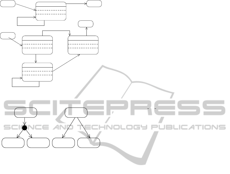
state 1
OnEntry { }
OnExit { }
{ }
state 2
OnEntry { }
OnExit { }
{ }
expression_1
expression_2
expression_3
Figure 1: Basic elements of the notation.
useful for declarative modelling.
Our FSMs will be of a synchronous type. The
set E are expressions. T is usually a partial func-
tion, that is, there are pairs (s
i
,e
t
) for which T is not
defined; so, T is usually called the transition table.
The standard general description of the semantics for
T (s
i
,e
t
) = s
j
is that when the machine is in state s
i
∈ S
and if the expression e
t
evaluates to true, the machine
will move to the state s
j
. However, this requires that,
(for any t 6= s), if T (s
i
,e
t
) and T (s
i
,e
s
) are defined
and T (s
i
,e
t
) 6= T (s
i
,e
s
), then e
t
and e
s
never be true
simultaneously (unless one is modelling completely
non-deterministic behaviour).
We simplify the burden for the behaviour designer
by making the projection of T on each state a se-
quence instead. That is, T (s
i
,e
t
) = s
j
will cause a
transition to state s
j
if e
t
evaluates to true and no pre-
vious expression e
s
evaluates to true (∀s < t in the
sequence T (s
i
,·)). Note that while this is simply syn-
tactic sugar, it does make the task of the behaviour
designer a lot simpler.
In a FSM, each state models a period in time
where an action
1
takes place. However, there are three
sections where actions are grouped. An OnEntry
section is executed upon arrival to the state, while ac-
tions in the OnExit section are executed as the ma-
chine departs that state. Thus, the actions in these two
sections are executed once and only once. The third
section is a section for internal actions
2
that are exe-
cuted only if none of the transitions fires. When the
internal actions are completed, execution returns to
evaluate the sequence of expressions that label tran-
sitions out of the state and the cycle is repeated. We
refer to one pass over the cycle as a ringlet.
Because our models consist of arrangements of
FSMs, variables used in each of the sections above
are of 3 types. The first type, local variables, are ex-
clusive to one and only one FSM (that is their scope
is only the states of one FSM). Internal variables
are shared by all the FSMs in the arrangement (that
is, their scope is all the states of the FSMs in the ar-
rangement). Finally, external variables are variables
whose scope goes even beyond the arrangement of the
1
We make no distinction between actions and activities,
and more on this will be discussed later.
2
In UML known as the do section.
FSMs and in embedded systems, are variables that are
set by external sensors or are set to activate effectors
and actuators. The environment that holds the vari-
ables is named the whiteboard (Hayes-Roth, 1988),
but it also correspond to the software architecture pat-
tern of a repository (Sommerville, 2010).
By design, in one ringlet execution there is only
one read operation by which a local copy of exter-
nal and internal variables in the scope of the current
FSMs is made before the execution of any section or
the evaluation of any expression labelling any transi-
tion. That is, all execution in a ringlet is in the same
context that is not modified by any other concurrent
FSM or any external event (a new sensor reading, for
example). If no transition fires and the internal actions
complete, when a new ringlet commences, a new read
of the external scope will take place. All writes of
external or internal variables by a FSM take place im-
mediately in the shared context.
The arrangement of FSMs is executed by a round-
robin switch from one ringlet of one FSMs to the
next one in the arrangement. Thus, the arrange-
ment of FSMs is a single sequential execution, exe-
cuted by one thread that interprets the semantics de-
scribed above. It is possible also to indicate a rela-
tive frequency for each FSMs enabling different rates
of progress which are implemented by each FSMs
having a certain number of ringlets performed be-
fore passing the execution token to the next FSM in
the arrangement. Note that this style of execution is
very much in line with the time-triggered architec-
ture (Kopetz and Bauer, 2003) (as opposed, as we
mentioned earlier, to an event-driven architecture).
We make a first contrast with other approaches.
Historically, the de-facto standard for FSMs is de-
rived from the STATEMATE model (Harel and Naamad,
1996; Harel et al., 1990) but there have been many al-
ternative proposals (von der Beeck, 1994). There are
several commercial products including QP
TM
(Samek,
2008), BotStudio (Michel, 2004) StateWORKS (Wag-
ner et al., 2006) and MathWorks
R
StateFlow. The
UML form of FSMs derives from OMT (Rumbaugh
et al., 1991, Chapter 5), and the MDD initiatives of
Executable UML (Mellor and Balcer, 2002). In all
of these, the set E is a set of events, or a set of in-
put symbols. But, in UML 2 and other FSM lan-
guages that enable guard conditions, a need appears
to recommend best practices (Klotzbuecher, 2012),
where the exclusive disjunction of all guard condi-
tions out of a state shall always be true. Also, in
UML 2 and STATEMATE, two transitions from a sin-
gle state that evaluate to true represents a conflict and
an invalid configuration. This is not a concern in
our modelling language. Expressions out of a state
ArrangementsofFinite-stateMachines-Semantics,Simulation,andModelChecking
183

form a list (in Fig. 1 we have indicated this by a se-
quence numeral) and thus, the second expressions can
be seen as the conjunction with the negation of the
first. MathWorks
R
, StateFlow with Symlink concurs
with our approach and specifies a sequential evalu-
ation of only one event at a time and a mechanism
to specify priorities in transitions but its larger set of
primitives and its semantics requires complex transla-
tions for performing model-checking (Agrawal et al.,
2004).
Our use of a single-thread execution for the sev-
eral FSMs in the arrangement, as opposed to paral-
lelisation by a semantics that just specifies concur-
rency (that is arbitrary rate of progress for each, as
each is executed within an independent thread) brings
several advantages. It has been argued that from the
design point of view, open concurrency (where the
management of switches between threads is left to
the system) represents an unnecessary cognitive load
in the model designer (Breen, 2004) as it opens all
sorts of needs for communication, synchronisation
and consideration of communication delays. There
is added complexity in ensuring properties like fair-
ness, management of critical sections, no deadlock,
and extermination of starvation. It is also the case
that the execution (that is implementation) is usu-
ally less efficient, as concurrency control mechanisms
consume CPU cycles and may need to manage con-
text switches and communication primitives with na-
tive support from the operating system or the hard-
ware. Perhaps more important is actual formal veri-
fication that models are correct. Model-checking of
systems that enable concurrent threads must consider
a universe of all possible states of the system, repre-
sented by the Cartesian product of all possible states
of each thread. This combinatorial explosion signif-
icantly complicates the formal verification of such a
system. For robotic systems and embedded systems
where there may be several timing requirements, se-
quential execution has been proposed as superior to
the multiplication of threads (Merz et al., 2006).
By using sequential scheduling we maintain
concurrency, and the models produced with the
logic-labelled FSMs can be verified using model-
checking technology (NuSMV) within a matter of sec-
onds (Estivill-Castro et al., 2012c; Coleman et al.,
2012), while for the same case studies, but using Be-
havior Trees – which have explicit notation for spawn-
ing parallel threads – require several days of CPU to
verify equivalent properties (Grunske et al., 2011).
It is important to note that the approach presented
here is not a departure from the event model of tradi-
tional FSMs. In fact, the ability of our FSMs to use
statements in a decidable common-sense logic allows
for a more complex event definition with clear value
and temporal semantics (Billington et al., 2010). Sen-
sors that trigger events in an embedded system are
mapped to external variables of which a snapshot is
taken at the read pre-determined point at the start of
the ringlet (Estivill-Castro et al., 2012a). Our choice
to place only one read instance of the variables per
ringlet may seem to contradict the STATEMATE “exe-
cution time” requirement that suggest changes in any
point in time should be reflected in the next. How-
ever, STATEMATE’s approach creates serious problems
in robotics applications where there is an open en-
vironment (Klotzbuecher, 2012), and languages like
rFSM also take an approach to evaluate the set of tran-
sitions out of a state in the same context.
3 MODULARISATION
Harel’s state charts (Harel and Politi, 1998) intro-
duced a hierarchy of states, i.e., states that themselves
contain other states; providing abstraction and modu-
larisation for the construction of larger models. Mod-
ularity is a very powerful design tool (Baldwin and
Clark, 2000) and such sub-machines can be re-used,
facilitating the design of behaviours as components.
With our approach, modularity is achieved
through a model of suspension. Each FSM has a
SUSPENDED state. In its SUSPENDED state, a ma-
chine simply passes the execution token to the next
FSM in the arrangement. Our language offers spe-
cialised expressions to control suspension. The ex-
pression suspend(machine id) triggers an implicit
transition in the FSM identified by machine id from
its current state to its SUSPENDED state, record-
ing what the current state was. The expression
resume(machine id) triggers an implicit transition
of the corresponding machine (from its SUSPENDED
state) back to the recorded, previous state. The ex-
pression restart(machine id) triggers an implicit
transition of the machine from its SUSPENDED state to
the machine’s initial state (effectively restarting the
machine from the beginning).
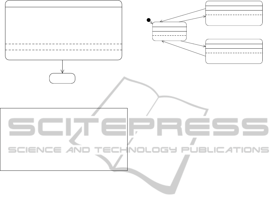
Because modularity is an important design tool,
and although a hierarchy of FSMs machines is not
enforced, our flexibility enables the construction of
a very powerful notion of submachine. To do
this, the parent machine places the corresponding
restart(sub machine id) in its OnEntry section,
and the corresponding suspend(sub machine id)
in its OnExit section. If the corresponding sub-
machine, creates itself a further level of sub-
machines, then the sub-machine puts suspend in-
structions for its sub-machines in the OnEntry sec-
MODELSWARD2013-InternationalConferenceonModel-DrivenEngineeringandSoftwareDevelopment
184

state 1
OnEntry { }
OnExit { }
{ }
submachine_ID with
substates
sub_state_1
sub_state_2
expression_1
expression_3
expression_2
state 1
OnEntry { }
OnExit { }
{ }
state invokes submachine
OnEntry { start(submachine_ID); }
OnExit { suspend(submachine_ID); }
{ }
expression_1
expression_3
sub_state_1 sub_state_2
expression_2
suspend
submachine_ID_is_suspended
submachine_ID_is_suspended
submachine_ID_shall_restart
submachine_ID_shall_restart
Note..
start(submachine_ID)
{
submachine_ID_shall_restart:=true;
submachine_ID_is_suspended:=false;
}
Note..
suspend(submachine_ID)
{
submachine_ID_shall_restart:=false;
submachine_ID_is_suspended:=true;
}
Figure 2: Semantics of the submachines in terms of the basic structures. The code in the notes and the arrows with a triangle
head (which have highest priority for each state) are implicit (they are never drawn; they are embedded in the interpreter).
tion of its own SUSPEND state. This pattern is illus-
trated in Fig. 2. Moreover, the restart, suspend and
resume instructions can create more flexible launch
and suspend patterns in an arrangement of FSMs.
In contrast, the Harel’s sub-machine model sug-
gests a certain level of concurrency (two threads,
one for the submachine and one for the parent ma-
chine). Breen (2004) identifies two issues with this,
(1) broadcasting of events, and (2) a need for struc-
tural priority to resolve which transitions in the stack
of nested states is to be evaluated. We point out to a
third fundamental problem due to nested states im-
plying concurrency or parallel execution. Namely,
the modelling tool, while powerful, leaves open the
scheduling of the threads of control that prescribes the
CPU cycles for each state. As a result, any model-
checking of the hierarchical state-charts must con-
sider all possible combinations of progress of each
thread (at instruction level, i.e. at a much lower level
than even a Kripke structure for the given FSMs).
This results in a combinatorial explosion that compli-
cates (and in most cases makes infeasible) the practice
of formal model-checking.
We do have concurrency in our modelling lan-
guage. But we specify the semantics of the schedule.
First, we have a single thread of control. Second, we
have structured, as a sequence, the transitions lead-
ing out of each state. Thus, we can have machines
in an arrangement that are not required to be sub-
machines, resolving the three fundamental problems
mentioned in the previous paragraph. Note that oth-
ers (Merz et al., 2006) – in particular, the rFSM lan-
guage (Klotzbuecher, 2012) – have also chosen to re-
move the parallelism of state-charts because of these
issues. Also note that while STATEMATE and UML 2
both use structural priority, the order of priorities is
reversed. UML 2 assigns higher priority to transitions
in deeper nested states.
We stress the importance of the semantics of our
submachine model in comparison with UML and
STATEMATE. The hierarchical machines of UML,
with independent threads for the machine and sub-
machines, implies that the evaluation of a transac-
tion in a submachine overlaps with the transition of
higher states in the hierarchy and examples show that
this can lead to stuck execution. UML 2.1 circum-
vents this problem by prohibiting the initial transition
from defining guard conditions, but introduces a se-
mantic point variation that leaves open the semantics
of transitions to composite states without initial con-
ditions. STATEMATE semantics can also lead to code
that gets stuck (there are semantical differences be-
tween simulated and generated code (Harel and Naa-
mad, 1996, page 303)). Our deterministic seman-
tics completely avoids this issue and maintains con-
currency. In robotic systems, and embedded systems
with only one (single-core) processor, parallel execu-
tion is just conceptual, as the system would always
execute a sequential schedule (albeit with the concur-
rency issues pointed out above). We do not lose the
conceptual modularity of several FSMs but add much
clearer modelling capabilities (and reliability due to
execution determinism).
4 TRANSITIONS
Our transitions do not have events, as we indicated,
but an event causes (in our reference implementation)
a change of a Boolean variable event hasHappened
in a whiteboard. Thus, the UML form event [ guard
] / effect of a transition is in fact the conjunction
of the Boolean variable event hasHappened and the
guard. So, the expressivity is the same but we han-
ArrangementsofFinite-stateMachines-Semantics,Simulation,andModelChecking
185

dle the above structure by event hasHappened &&
guard / effect. Consider robotic soccer; the vi-
sion module sets the variable ballIsVisible in the
whiteboard and this is the expression that switches
from a state of searching for the ball to a behaviour
that seeks the ball.
We only have effects with a very clear semantics.
We take the view that the OnEntry for S is executed
once and exactly once. And naturally, the OnExit for
S is part of the transition leaving S. We allow effects
only thus as an intermediate virtual state. That is, ef-
fects are just syntactic sugar for a model with an inter-
mediate state (Fig. 3). This now explains why we do
not distinguish between atomicity and non-atomicity
of the do section of a state as all the executable code
corresponding to the arrangement of FSMs is sched-
uled sequentially and execution of any code in the ar-
rangement cannot be preempted by another section of
code in the model. That is, there is no distinction in
our language between activities and actions.
This makes very clear that in our semantics, tran-
sitions belong to the source state, and finish in a target
state. We note that other FSM modelling languages
(for example rFSM) require transitions actually to de-
part a set of active states (this is mainly due to the
hierarchical nesting of states discussed earlier).
In contrast, UML’s event-labeled transitions
present challenges. Note that transitions labeled with
the conjunction of events
event 1 && event 2[guard]/effect.
have inspired the debate of “event history” as the tran-
sition would not “fire” unless both events happen “at
the same time”. Thus, even event-based FSMs use
some event-history mechanism, but in our case, the
concerns regarding event-history are removed from
the behaviour designer and are simply handled in the
sensor-rate update of the whiteboard.
The effects component (and also OnEntry and
OnExit sections) usually cause variation points or
undefined semantics. In UML, and its variants, ef-
fects are actions (and thus atomic, the OnEntry and
OnExit sections of states are also atomic), and cannot
be interrupted, to avoid these semantic issues. The
problem of being interrupted is the result of the pos-
sible existence of another thread in the hierarchy of
nested states which can raise an event for which we
have a transition now. The UML, and its variants, de-
clare OnEntry and OnExit sections, like effects, as
parts of the transition. However, even in this case, it
is not always clear that the OnEntry section of a state
S is part of the previous transition that moved control
to the state S. This is extremely important as the cur-
rent state S may have a transition simply labeled true
and with the highest priority.
cond1 / effects 1
condN / effectsN
state 1
OnEntry { action 1.1 }
OnExit{ action 1.2 }
{ action 1.3}
state 2
OnEntry { action 2.1 }
OnExit{ action 2.2 }
{ action 2.3}
state 1
OnEntry { action 1.1 }
OnExit{ }
{ action 1.3}
virtual state cond1
OnEntry {effects 1}
OnExit{ action 1.2 }
{ }
state 2
OnEntry { action 2.1 }
OnExit{ action 2.2 }
{ action 2.3}
virtual state condN
OnEntry {effects N }
OnExit{ action 1.2 }
{ }
cond1
condN
1
1
state N
OnEntry { action N.1 }
OnExit{ action N.2 }
{ action N.3}
state N
OnEntry { action N.1 }
OnExit{ action N.2 }
{ action N.3}
Figure 3: Transition effect part is an OnExit section for
a separate, virtual state.
This also raises the issue of boundary-crossing
transitions. Simons (2000) has already argued the re-
dundancy of these types of transitions as well as the
conceptual challenges caused to behaviour designers
by allowing these. Note also that this use caused re-
vision from UML 2 to UML 2.1 (in particular the in-
troduction of multiple exit points) and that further is-
sues were addressed in UML 2.3 making the owner of
a transition the least-common ancestor (LCA). Note
that our language keeps things simple, and avoids
all these issues completely, siding with Simon’s ar-
gument. That is, boundary-crossing transitions are
impossible to be drawn. The implicit transitions of
the restart and resume mechanism described be-
fore are just syntactic sugar that avoid requiring a sep-
arate, explicit suspend state replicated for every state
in an FSM and corresponding transitions back to the
previous state and the initial state.
The issue of a hierarchy of states and the LCA
is a result of state hierarchies. UML allows internal
transitions (although UML leaves open their priority
with respect to self-transitions), because in a state-
hierarchy these are not redundant; but otherwise they
are (Simons, 2000). Thus, we also do not include in-
ternal transitions in our language. Recall that an in-
ternal transition is a self-transition (that is a transi-
tion with the same source and target state) but where
neither the OnEntry nor the OnExit sections execute
(while a self-transition is an ordinary transition that
executes the OnEntry and the OnExit sections). If
the behaviour designer wishes to express an internal
transition, we suggest the pattern of Fig. 4.
4.1 Pseudo-states
This discussion takes us to the UML concept of
pseudo-states. We do have initial pseudo-states, in-
MODELSWARD2013-InternationalConferenceonModel-DrivenEngineeringandSoftwareDevelopment
186
departure
state 1
OnEntry { action 1.1 }
OnExit{ action 1.2 }
{ action 1.3}
arrival
1
state
after
state
before
internal / effects
state 1
OnEntry { action 1.1 }
OnExit{}
{ action 1.3 }
state
before
state
after
virtual state 1
OnEntry { effects }
OnExit{ }
{ action 1.3}
virtual state 2
OnEntry { }
OnExit{ action 1.2}
{ }
departure
departure
internal
arrival
internal
Figure 4: Internal transitions are relevant only for their ef-
fect and can be constructed with this pattern.
S
a
b c
T1 T2
S
a && b a && c
T1 T2
Figure 5: A junction (left) modelled through a common
clause a (right).
dicated by the full-circle. The semantics is clearly
the corresponding point in the ringlet of the state S
pointed by the arrow from the initial pseudo-state
(namely, just before the OnEntry of S). But, we do
not have UML’s choice pseudo-states in our transi-
tions at all. Note that UML recommends the use of an
else transition with the use of choice as execution be-
coming stuck is otherwise a possibility. Without loss
of generality, we simply remove this. Correspond-
ingly, we treat UML’s junction simply as syntactic
sugar to factor out a common clause in a conjunction
(as illustrated in Fig. 5).
Naturally, the issues with the open thread leads to
exit and entry pseudo-states in UML, but with a very
delicate semantics that varies whether the pseudo-
state is drawn inside the sub-state or in the boundary.
This danger has been noticed by rFSM and we follow
their approach by simply eliminating them.
UML then offers a Completion Event as a syn-
chronisation event for the possibility of the do sec-
tion being interrupted and other sub-states waiting for
such completion as well. UML also assumes unre-
alisticly that the departure of a state implies the ar-
rival to an exit pseudo-state of all its sub-machines
(and the termination of their activities). This is unre-
alistic even in the multi-threaded realisation unless a
native operating-system call can abort those threads.
Any other realisation where the sub-thread are actu-
ally waiting for a signal so themselves send a sig-
nal to halt a device (say a thread is in control of the
motor) depends on the priorities given by the thread
management to deliver the signal to the thread, and
for this one to have a sufficient CPU slice in order
for itself to send the halting signal to the motor con-
troller. We claim that our synchronised scheduling is
thus more effective. We can predict how many steps
will be needed for the thread controlling the motor
to become live and perform its read of the signal in
the whiteboard and then shut down the motor. Such
predictability has been demonstrated by our model-
checking of several case studies.
We do not have any explicit representation of final
or terminate pseudo-states (similarly to rFSM). Our
arrangement of machines maintains variables of the
form machine ID isRunning that enables the dis-
covery that some machine in the arrangement is in
its suspended state or has reached a final state. Such
completion happens when a FSM reaches a state with-
out any transition departing. This effectively removes
the machine form the scheduling.
The UML history pseudo-state is covered by our
resume primitive, but without the need that occurs in
UML of enabling deep and shallow history pseudo-
states (that again are a result of the parallel threads of
hierarchical states). Finally, the synchronous model
proposed here also makes superfluous the UML join
and fork pseudo-states, and UML deferred events. An
aspect that UML allows is inheritance between FSMs;
our language currently does not support this, but to
the best of our knowledge, to date, nobody else has
chosen to to include such a facility.
5 EXAMPLES
We have successfully used our approach to model
and implement numerous case studies. Perhaps most
importantly, we have been able to uncover hidden
complexities and errors in prior modelling of soft-
ware engineering problems (Winter and Yatapanage,
; Grunske et al., 2011). To this end, we have both
performed formal model checking (Estivill-Castro
et al., 2012c) as well as simulation of system be-
haviour (Coleman et al., 2012).
The first example where we used an arrangement
of FSMs is a widely studied case of a micro-wave
oven. The model can be fully verified by formal
model-checking (even with integer variables in the
timer) and it can be executed as a Java program on an
NXT robot or a C++ program on a Nao robot. This il-
ArrangementsofFinite-stateMachines-Semantics,Simulation,andModelChecking
187
ORANGE_BLOB_FOUND
OnEntry { extern blobSizeX; extern blobSizeY;
extern blobArea; extern blobNumPixels;
toleranceRatio = 2; densityTolerance = 3;
badProportionXY = blobSizeX/blobSizeY > toleranceRatio;
badProportionYX = blobSizeY/blobSizeX > toleranceRation;
badDensityVsDensityTolerance =
blobArea / blobNumPixels > densityTolerance;
}
OnExit {}
{}
BALL_FOUND
is_it_a_ball
Figure 6: Section of the vision pipeline to recognise a blob
of orange as a ball.
% BallConditions.d
name{BALLCONDITIONS}.
input{badProportionXY}.
input{badProportionYX}.
input{badDensityVsDensityTolerance}.
BC0: {} => is_it_a_ball.
BC1: badProportionXY => ˜is_it_a_ball. BC1 > BC0.
BC2: badProportionYX => ˜is_it_a_ball. BC2 > BC0.
BC3: badDensityVsDensityTolerance => ˜is_it_a_ball. BC3 > BC0.
output{b is_it_a_ball, "is_it_a_ball"}.
Figure 7: Theory that defines when a blob is a ball.
lustrates the language independence and platform in-
dependence of this MDD approach. The model can
also be simulated (Coleman et al., 2012) and has been
subjected to fault injection to produce FMEA tables
for the analysis of failure-robustness (Estivill-Castro
et al., 2012c; Estivill-Castro et al., 2012a).
Two examples where this approach has been suc-
cessful in performing simulation, model-checking,
and execution across platforms, are a Mine Pump and
an Industrial Press (Coleman et al., 2012; Estivill-
Castro et al., 2012c; Estivill-Castro et al., 2012a).
A fourth case study where simulation and model-
checking has been very effective has been the Ambu-
latory Infusion Pump (Estivill-Castro et al., 2012b).
That case study utilises multiple submachines.
In a fifth example, these FSMs have also been
used to include a planner, with re-planning (in the
sense of artificial intelligence) into the capabili-
ties of a robot while maintaining platform indepen-
dence (Ferrer Mestres, 2012).
Our FSMs are used by the MiPal team at
RoboCup. We now show here a sixth example
of combining a non-monotonic logic with a vision
pipeline to illustrate how powerful the combination
of a declarative language with the arithmetics facili-
tated of an imperative language can be. To illustrate
the power of combining the arithmetic provided by
WAIT_FOR_BALL
OnEntry {}
OnExit {}
{}
HEAD_RIGHT
OnEntry {}
OnExit {}
{
post("NaoHeadPositionChange", "-9 0 .3");
}
BallIsRight
BallIsLeft
~BallIsRight
~BallIsLeft
HEAD_LEFT
OnEntry {}
OnExit {}
{
post("NaoHeadPositionChange", "9 0 .3");
}
Figure 8: A simple ball tracker.
simpleC with the declarative nature of DPL we show
a simple example of filtering for image recognition
of objects in robotics. In particular, in robotic soccer
(RoboCup), images are processed at a frame rate of
30 frames per second by a vision pipeline that, after
segmentation, builds blobs of colours. We illustrate
the filtering of blobs by the declarative language (this
is basically a description of when a blob is considered
a ball, and, for simplicity, we ignore many other as-
pects). Suffice it to say that usually, a blob of orange
should be recognised as a ball (this is rule BC0 in the
DPL file; see Fig. 7).
However, if the blob’s size on the X axis is much
larger than the blob’s size in the Y direction, it is con-
sidered a rectangular blob, far from the more square-
shaped blob that corresponds to a ball (the blob is the
smallest bounding rectangle that contains the orange
pixels); thus, this is not a ball (rule BC1). Similarly, if
the blob’s size for Y with respect to the X size (this is
rule BC2) and both of these rules defeat rule BC0; thus
we have the relations BC1 > BC0 and BC2 > BC0. Fi-
nally, if the number orange of pixels is much smaller
than the area of the blob in pixels, there are many
gaps of non-orange and it should not be considered
a ball (rule BC3 which also defeats BC0). Incremen-
tally, more sophisticated and refined revisions on the
conditions can be made by adding rules to the theory
of Fig. 7, while the arithmetic is kept in Fig. 6.
Also, in robotics, a traditional topic is the track-
ing of an object by a feedback control (and can also
be illustrated by Robotic soccer) as the robot tracks
the ball. Such tracker can be coded in our modelling
language and it appears in Fig. 8.
REFERENCES
Agrawal, A., Simon, G., and Karsai, G. (2004). Seman-
tic translation of simulink/stateflow models to hybrid
automata using graph transformations. Electr. Notes
Theor. Comput. Sci., 109:43–56.
Baldwin, C. Y. and Clark, K. (2000). Design Rules, The
Power of Modularity. MIT Press, Cambridge, MA.
MODELSWARD2013-InternationalConferenceonModel-DrivenEngineeringandSoftwareDevelopment
188

Billington, D., Estivill-Castro, V., Hexel, R., and Rock, A.
(2010). Non-monotonic reasoning for requirements
engineering. In 5th Int. Conf. on Evaluation of Novel
Approaches to Software Engineering (ENASE), pages
68–77, Athens. SciTePress (Portugal).
Breen, M. (2004). Statecharts: Some critical observations.
Coleman, R., Estivill-Castro, V., Hexel, R., and Lusty, C.
(2012). Visual-trace simualtion of concurrent finite-
state machines for valdiation and model-checking of
complex behavior. In SIMPAR 3rd Int. Conf. on Sim-
ulation, Modeling and Programming for Autonomous
Robots, volume 7628, pages 52–64, Tsukuba, Japan.
Springer-Verlag LNCS.
Eshuis, R. (2009). Reconciling statechart semantics. Sci-
ence of Computer Programming, 74(3):65–99.
Estivill-Castro, V., Hexel, R., and Rosenblueth, D. A.
(2012a). Efficient model checkign and FMEA analy-
sis with deterministic scheduling of transition-labeled
finite-state machines. In 2012 3rd World Congress
on Software Engineering (WCSE 2012), pages 62–72,
Wuhan, China. IEEE CPS.
Estivill-Castro, V., Hexel, R., and Rosenblueth, D. A.
(2012b). Efficient modelling of embedded soft-
ware systems and their formal verification. In
The 19th Asia-Pacific Software Engineering Conf.
(APSEC 2012), Hong Kong. IEEE. to appear.
Estivill-Castro, V., Hexel, R., and Rosenblueth, D. A.
(2012c). Failure mode and effects analysis (FMEA)
and model-checking of software for embedded sys-
tems by sequential scheduling of vectors of logic-
labelled finite-state machines. In System Safety, The
7th Int. IET System Safety Conf.,, Edinburgh, UK.
Ferrer Mestres, J. (2012). Implementation of a planning
module for a Nao robot. Universitat Pompeu Fabra,
Escola Superior Polit
`
ecnica. Projecte Fi de Carrera.
Grunske, L., Winter, K., Yatapanage, N., Zafar, S., and
Lindsay, P. A. (2011). Experience with fault injec-
tion experiments for FMEA. Software, Practice and
Experience, 41(11):1233–1258.
Harel, D., Lachover, H., Naamad, A., Pnueli, A., Politi, M.,
Sherman, R., Shtull-trauring, A., and Trakhtenbrot,
M. (1990). Statemate: A working environment for
the development of complex reactive systems. IEEE
Transactions on Software Engineering, 16:5.
Harel, D. and Naamad, A. (1996). The STATEMATE se-
mantics of statecharts. ACM Transactions on Software
Engineering Methodology, 5(4):293–333.
Harel, D. and Politi, M. (1998). Modeling Reactive Sys-
tems with Statecharts: The STATEMATE Approach.
McGraw-Hill.
Hayes-Roth, B. (1988). A blackboard architecture for con-
trol. In Distributed Artificial Intelligence, pages 505–
540, San Francisco, CA, USA. Morgan Kaufmann.
Hopcroft, J., Motwani, R., and Ullman, J. (1979). Introduc-
tion to Automata Theory, Languages, and Computa-
tion. Addison-Wesley Publishing Co., Reading, MA.
Klotzbuecher, M. (2012). rFSM v1.0-beta6.
www.orocos.org/rfsm.
Kopetz, H. and Bauer, G. (2003). The time-triggered archi-
tecture. Proc. of the IEEE, 91(1):112–126.
L
¨
otzsch, M., Bach, J., Burkhard, H.-D., and J
¨
ungel, M.
(2004). Designing agent behavior with the extensi-
ble agent behavior specification language XABSL. In
7th Int. Workshop on RoboCup, volume 3020, pages
114–124. Springer LNAI.
Mellor, S. J. and Balcer, M. (2002). Executable UML: A
foundation for model-driven architecture. Addison-
Wesley Publishing Co., Reading, MA.
Merz, T., Rudol, P., and Wzorek, M. (2006). Control system
framework for autonomous robots based on extended
state machines. In Int. Conf. on Autonomic and Au-
tonomous Systems, ICAS, page 14, Silicon Valley, CA.
Michel, O. (2004). Webots: Professional mobile robot sim-
ulation. J. Advanced Robotics Systems, 1(1):39–42.
Risler, M. and von Stryk, O. (2008). Formal behavior speci-
fication of multi-robot systems using hierarchical state
machines in XABSL. In AAMAS08-Workshop on For-
mal Models and Methods for Multi-Robot Systems,
Estoril, Portugal.
Rumbaugh, J., Blaha, M. R., Lorensen, W., Eddy, F., and
Premerlani, W. (1991). Object-Oriented Modelling
and Design. Prentice-Hall, Englewood Cliffs, NJ.
Samek, M. (2008). Practical UML Statecharts in C/C++,
Second Edition: Event-Driven Programming for Em-
bedded Systems. Newnes.
Simons, A. (2000). On the compositional properties
of UML statechart diagrams. In Rigorous Object-
Oriented Methods 2000, York, UK. Electronic Work-
shops in Computering (eWiC).
Sommerville, I. (2010). Software engineering (9th ed.).
Addison-Wesley Longman, Boston, MA, USA.
von der Beeck, M. (1994). A comparison of statecharts
variants. In 3rd Int. Symp. Organized Jointly with the
Working Group Provably Correct Systems on Formal
Techniques in Real-Time and Fault-Tolerant Systems,
ProCoS, pages 128–148, UK. Springer-Verlag.
W3C (2012). State chart XML (SCXML): State
machine notation for control abstraction.
www.w3.org/TR/2012/WD-scxml-20120216/.
Working Draft.
Wagner, F., Schmuki, R., Wagner, T., and Wolstenholme,
P. (2006). Modeling Software with Finite State Ma-
chines: A Practical Approach. CRC Press, NY.
Winter, K. and Yatapanage, N. The mine pump case study.
Technical report, University of Queensland. supple-
ment in www.itee.uq.edu.au/˜docs/FMEA.
ArrangementsofFinite-stateMachines-Semantics,Simulation,andModelChecking
189
