
A General Framework for the Development of MDD Projects
Beatriz Mar
´
ın
1
, Javier Pereira
1
, Giovanni Giachetti
2
, Felipe Hermosilla
1
and Estefan
´
ıa Serral
3
1
Escuela de Ingenier
´
ıa Inform
´
atica y Telecomunicaciones, Universidad Diego Portales, Santiago, Chile
2
Escuela de Inform
´
atica, Universidad Andr
´
es Bello, Santiago, Chile
3
Christian Doppler Laboratory ”Software Engineering Integration for Flexible Automation Systems”,
Vienna University of Technology, Vienna, Austria
Keywords:
Model-driven Development (MDD), General Framework, MDD Tools.
Abstract:
The main characteristic of the Model-Driven Development paradigm is that it allows the automatic (or semi-
automatic) generation of software systems from the conceptual models that specify these systems. The suc-
cessful application of MDD relies in the selection of appropriate diagrams and tools. However, software
engineers do not have frameworks that help them to select the MDD tools that better fit to specific projects
needs. To face this issue, in this paper we have analysed a set of models and tools that can be used to support
MDD projects. From this analysis, a general framework is presented.
1 INTRODUCTION
The MDD paradigm presents several advantages re-
garding traditional software developments. For in-
stance, MDD reduces the programming effort and
technical complexity involved, software products are
consistent with documentation, etc. These advantages
have motivated the emergence of several modeling
proposals and MDD tools related to different appli-
cation domains and development stages.
One of the key aspects for the successful appli-
cation of MDD relies in the decisions that software
engineers perform at the moment of selecting MDD
approaches and tools. To do this, software engineers
need to take informed decisions about which are the
most suitable tools to use in accordance to specific sit-
uations. However, at the best of our knowledge, there
not exist a general framework for the selection of ap-
propriate MDD tools depending of the context of the
projects to be developed.
In this paper, we present a general framework that
is centered on the selection and configuration of a spe-
cific set of diagrams and related MDD tools in order to
support the execution of concrete MDD projects. This
framework is supported by a recommendation system
that helps software engineers in the selection of inter-
esting combinations of MDD tools.
The rest of the paper is organized as follows: Sec-
tion 2 presents a general MDD framework, and Sec-
tion 4 presents our conclusions and further work.
2 A MDD FRAMEWORK
At the moment of starting an MDD project, software
engineers need to decide the diagrams that will be
used in the software development in accordance to the
application domain. Thus, software engineers must
know what modelling artefacts can be used as CIM,
PIM, PSM, and PM. This is not an easy step due to
different modelling approaches/tools provide differ-
ent facilities to represent the views of the system. For
instance, a class diagram represents the static view,
but it is inappropriate for specifying behavior.
Thus, software engineers must perform a match-
ing among the modelling approaches selected, the
MDA models involved, and the views that are neces-
sary for the proper specification of the intended sys-
tem. Later, software engineers select or implement
the tools that support these models in order to carry
out the software development process, and the corre-
sponding model transformations.
All these decisions mainly depend on the experi-
ence and knowledge of software engineers. As conse-
quence, there are powerful MDA tools that may be not
considered in a project development just due to their
lack of knowledge. Also, inexperienced software en-
gineers may not know how to combine the different
diagrams involved. As consequence risky and costly
software developments may be carried out.
To face these problems, we propose a general
framework that combines the MDA models, the di-
257
Marín B., Pereira J., Giachetti G., Hermosilla F. and Serral E..
A General Framework for the Development of MDD Projects.
DOI: 10.5220/0004319402570260
In Proceedings of the 1st International Conference on Model-Driven Engineering and Software Development (MODELSWARD-2013), pages 257-260
ISBN: 978-989-8565-42-6
Copyright
c
2013 SCITEPRESS (Science and Technology Publications, Lda.)

agrams that can be used as CIM, PIM, PSM or PM,
and the tools that support these models in the domain
of management information systems (MIS).
• The Computation Independent Model. CIM
represents the requirements of a system. In this
model, the UML Use Case diagram and the
UML Activity diagram can be used. Diagrams
oriented to the organizational analysis and
identification of business element that will
be supported by the system corresponds to
CIM as well. This is the case of goal oriented
requirements diagrams (Dardenne et al., 1993),
as well as strategic analysis diagrams. For
instance, the i* diagram (Yu, 1995) and the
MAPS diagram (Bennasri et al., 2005) are
examples of these kinds of diagrams.
In addition, diagrams that represent the busi-
ness processes of an organization correspond to
CIM. This is the case of BPMN diagrams, such
us the proposal of (De La Vara et al., 2008).
• The Platform Independent Model. PIM must
have the different views that describe the
system holistically: the static/structural view,
the behavioural/functional view, and the
interaction/presentation view.
For the static/structural view, the UML Class
diagram, the UML object diagram, and the ER
diagram (Chen, 1976) can be used. For the be-
havioural/functional view, the UML State Ma-
chine, the UML Sequence, and the UML Col-
laboration diagrams can be used.
For the interaction/presentation view, we postu-
late that the OO-Method presentation diagram
(Pastor and Molina, 2007), and WebML Hy-
pertext diagram (Moreno et al., 2007) can be
used. At this point, it is important to men-
tion that in contrast to the structural and the be-
havioural view, only few proposals for the in-
teraction view are found in literature.
• The Platform Specific Model The PSM adds
some implementation details to PIM. Thus, the
UML component, the UML package, and the
UML deployment diagrams can be used.
• The Platform Model The PM corresponds to the
final code of the system. This model will
change depending on the technologies available
in a specific domain. For instance, for the MIS
domain, the PSM can be codified using ASP,
PHP, J2EE, .NET, Oracle, SQL, etc. For other
domains, different platforms can be used.
From the matching of diagrams and MDA models,
a general MDD framework related to the information
systems domain (see Figure 1) has been defined.
In Figure 1, dashed lines represent optional di-
agrams and optional transformations. For instance,
sometimes it is necessary to specify analysis diagrams
(such as i*) to properly identify the functional and
non-functional requirements of the system. Later,
these analysis models are transformed into the cor-
responding design artefacts (system views), such as
class diagrams (e.g. the proposal of (GIACHETTI
et al., 2010)), or even other analysis diagrams. Later,
the CIM model must be transformed to a system
model (PIM). Nevertheless, expert software engineers
could decide to go directly to the specification of PIM
models without using CIM models.
In the PIM model, it is necessary (at least) that
software engineers select a diagram that represents
the structural/static view, a diagram that represents the
behavioural/functional view, and a diagram that rep-
resents the interaction/presentation view. In Figure 1,
this situation is represented by rectangles with contin-
uous lines. However, the diagrams that are located in-
side of the rectangles are interchangeable each other.
In the MIS domain, the structural diagram is the core
diagram of a system. The rest of system views are
described from this diagram by using behavioural dia-
grams and interaction diagrams. Thus, we have drawn
a dashed line from the diagrams of the structural view
to the remaining views of the PIM model.
Then, PIM model must be transformed to the cor-
responding PSM model. Nevertheless, some tools go
directly from the PIM to the PM. The PSM model is
internally generated by the model compilation tools
in an automatic and transparent manner.
Finally, the platform specific model (PSM) is
transformed into the platform model (PM). In the gen-
eral MDD framework, we specified the PM as a 3-tier
architecture because it is commonly used for manag-
ment information systems. This architechture is com-
posed by a presentation tier, an application logic tier,
and a database tier. In Figure 1, a list of massive tech-
nologies has been located in each rectangle of the PM.
This general MDD framework is a starting point
for the development of an MDD project. Thus, other
diagrams, technologies, and transformations can be
added to the framework depending on the specific
needs of a project.
2.1 Matching MDA Tools and the
General MDD Framework
Once software engineers have decided the diagrams
that they will use in the specification of the MDD
project, is time to select the tools that support these
diagrams and the necessary transformations. A list of
57 tools and the respective companies was collected
MODELSWARD2013-InternationalConferenceonModel-DrivenEngineeringandSoftwareDevelopment
258
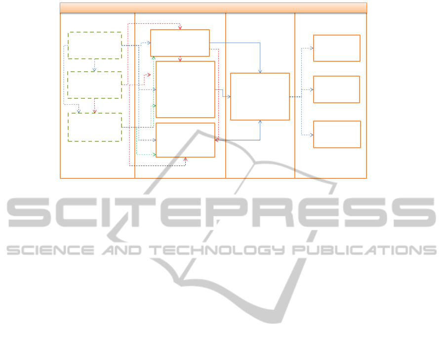
CIM
PIM
PSM
PM
I*'Diagram,
MAPS'Diagram
BP'Diagram
Use'Case'
Diagram,
Activity Diagram
Object Diagram
Class Diagram
E=R'Diagram
State Transition
Diagram
Sequence Diagram
Collaboration
Diagram
Functional Model
OO=Method
Presentation
Model
WebML Diagram
Component
Diagram
Package Diagram
Deployment
Diagram
ASP
JSP
PHP'
J2EE
.NET
SQL
ORACLE
MySQL
GENERAL'MDD'FRAMEWORK
Figure 1: A general MDD framework.
from the official OMG website and last updated in
march 9th of 2012. This list of tools was analyzed ac-
cording to the application domain, the diagrams sup-
ported for CIM, PIM and PSM, and the model com-
pilation facilities provided for PM generation.
From this analysis, there are 35/57 tools related to
the MIS domain. It is important to mention that most
of the tools analysed (20/35) do not specify the dia-
grams supported for the definition of CIM, PIM, or
PSM models; they only specify that UML diagrams
are supported. In this case, the MDA tools involved
correspond to pure model-compilation tools, which
provide importation facilities (through XML/XMI
files) from different UML modelling tools.
In addition, there is no one tool provides support
to all the models defined by MDA (CIM, PIM, PSM,
and PM). Thus, in a MDD project it is necessary to
combine two or more tools for achieving a complete
MDA process. This is not an easy task since tools se-
lection must be oriented to cover all (or most of) the
modelling and code generation needs, which are rep-
resented in terms of specific requirements for concrete
development processes.
2.2 Appliying a Multicriteria Decision
Framework
Let us consider that it is necessary to develop a confer-
ence system that automates the following tasks: send
a paper, asign reviewers, review the paper, and send
notifications to authors. To develop the conference
system in an MDD project, software engineers have
identified the necessity to specify a BPMN diagram
to understand the whole set of processes involved in
the submission task of a paper for a conference. This
specification will correspond to the CIM model.
Then, software engineers need to specify the PIM
model. Let us consider that software engineers have
some experience using the class and the state transi-
tion diagrams. Thus, the PIM model will consist of
a these diagrams and an interaction diagram. Finally,
let us consider that the conference system must be im-
plemented using the java platform.
Then, we apply a Multicriteria Decision Frame-
work in order to select a minimal set of tools that
cover these requirements for the conference system.
Figure 2 shows a subset of 24 tools extracted from
the list of tools analyzed from the OMG, and the five
requirements suggested above. Different algorithms
may be applied to solve this problem. However, sim-
ulations show that an algorithm proposed in (Paredes
and Pereira, 2010) is enough to identify the four non-
dominated tool-sets: 1) Integranova Model Execution
System, M-1 Global; 2) Integranova Model Execu-
tion System, Blu-Age; 3) ModelioSoft, MasterCraft;
4) Rational Software Architect, MasterCraft.
Notice that some tools appear in several solutions.
We could argue that these are robust tools in the sense
that they persistently take part of solutions. Although
robustness analysis is beyond the scope of the present
paper, it is important to remark that some kind of ex
post analysis need to be afforded by software engi-
neers in order to validate the recommended solutions.
3 RELATED WORK
In the work presented by (Mansell et al., 2006), an
MDD process framework is defined as a repository
of specific MDD processes, which have proven to
be successful in the industry and defines four differ-
ent models that go from a higher to a lower abstrac-
AGeneralFrameworkfortheDevelopmentofMDDProjects
259
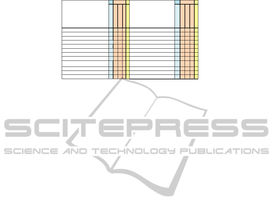
CIM
PM
CIM PM
BPMN
Class Diagram
State Machine Diagram
GUI
Java
BPMN
Class Diagram
State Machine Diagram
GUI
Java
@-portunity (Blueprint Software Modeler) 0 1 1 0 1 Model-In-Action (Mia Studio) 0 0 0 0 1
Aonix (Ameos) 0 0 0 0 1 MID (innovator) 1 1 1 0 0
BitPlan(smartGenerator) 0 0 0 0 1 Netfective (BlueAge) 1 0 0 0 0
Borland (Borland Together) 1 1 0 0 1 Outline Systems Inc (Power Rad) 0 0 0 0 1
Codagen Technologies (Codagen Architect) 0 0 0 0 1 Pathfinder Solutions (PathMate) 0 0 0 0 1
Codeless 0 1 1 1 0 Plastic Software (Agora Plastic) 0 0 0 0 1
EdCubed 1 1 0 0 0 Softaris Pty (MetaBoss) 1 0 1 0 0
Gentastic (e-Gen) 0 1 0 0 0 SoftTeam (ModelioSoft) 1 1 1 0 1
M-1 Global 1 0 0 0 0
CARE Technologies (Integranova Model
Execution System)
0 1 1 1 1
IBM (Rational software architect) 1 1 1 0 1 Sparx Systems (Enterprise Architect) 1 1 0 0 1
Interactive Object's Software (ArcStyler) 0 1 0 0 0 Tata Consultancy Services (MasterCraft) 0 0 0 1 0
Liantis (XCoder) 0 0 0 0 1 TechOne (Ace) 0 0 0 0 1
Company (tool)
PIM
Company (tool)
PIM
Figure 2: Example of application.
tion level. Apto (Jaroucheh et al., 2010) is an MDD
framework that takes into account the evolution of the
software development processes. This framework is
organized in four models: a process model, a con-
text model, an evolution model, and a linkage model.
These frameworks do not specify what are the dia-
grams needed to specify a system and how they can
be combined at the MIS domain. Moreover, related
works do not provide concrete references to the tools
that can be used in a specific project.
4 CONCLUSIONS
In this paper, a general MDD framework has been
presented. This framework characterizes the dia-
grams and tools that can be used in a MDA-based
process, thus reducing barriers between senior and
novice software engineers at the moment of putting
MDD projects into practice. This framework is gen-
eral, therefore, it is possible to add other MDD tools
with the diagrams that they support.
A multicriteria decision system has been applied
to an example of the use of the MDD framework. This
application allows the selection of the minimum set
of tools that satisfy the modeling needs of a specific
MDD project, which main advantage is the reduction
in the learning curve (less tools to be learned). Also, it
reduces the effort related to the implementation of in-
teroperability mechanisms among the different tools
selected. The future work plan to perform empirical
studies to validate the framework.
ACKNOWLEDGEMENTS
This work was funded by the TESTMODE FONDE-
CYT Project Ref. 11121395.
REFERENCES
Bennasri, S., Souveyet, C., and Rolland, C. (2005). Mod-
elling variability in requirements with maps. In
YAKHNO, T., editor, Advances in Information Sys-
tem. Springer, Berlin / Heidelberg.
Chen, P. (1976). The entity-relationship model - toward a
unified view of data. ACM Transactions on Database
Systems, (1):9–36.
Dardenne, A., Van Lamsweerde, A., and Fickas, S. (1993).
Goal-directed requirements acquisition. Science of
Computer Programming, (20).
De La Vara, J. L., S
´
Anchez, J., and Pastor, O. (2008). Busi-
ness process modelling and purpose analysis for re-
quirements analysis of information systems. In BEL-
LAHS
`
ENE, Z. and L
´
EONARD, M., editors, CAiSE.
Springer.
Giachetti, G., Alencar, F., Mar
´
In, B., Pastor, O., and Cas-
tro, J. (2010). Beyond requirements: An approach to
integrate i* and Model-Driven Development. In XIII
Congreso Iberoamericano en Software Engineering -
CIBSE 2010, Cuenca, Ecuador.
Jaroucheh, Z., Liu, X., and Smith, S. (2010). Apto:
A MDD-based generic framework for context-aware
deeply adaptive service-based processes. In IEEE In-
ternational Conference on Web Services. IEEE Com-
puter Society.
Mansell, J., Bediaga, A., Vogel, R., and Mantell, K. (2006).
A process framework for the successful adoption of
model driven development. In WARMER, A. R. A. J.,
editor, ECMDA-FA. Springer-Verlag, Berlin / Heidel-
berg.
Moreno, N., Fraternali, P., and Vallecillo, A. (2007).
WebML modeling in UML. IET Software, (1):67–80.
Paredes, F. and Pereira, J. (2010). A bi-criteria integer pro-
gramming and algorithmic approach for software ar-
chitecture alternatives modeling. In ALIO-INFORMS
Joint International Meeting, Buenos Aires, Argentina.
Pastor, O. and Molina, J. C. (2007). Model-Driven Architec-
ture in Practice: A Software Production Environment
Based on Conceptual Modeling. Springer, New York.
Yu, E. (1995). Modelling Strategic Relationships for
Process Reengineering. PhD thesis, University of
Toronto.
MODELSWARD2013-InternationalConferenceonModel-DrivenEngineeringandSoftwareDevelopment
260
