
A Meta-model for Tests of Avionics Embedded Systems
Alexandru-Robert Guduvan
1, 2, 3
, Hélène Waeselynck
1, 2
, Virginie Wiels
4
, Guy Durrieu
4
,
Yann Fusero
3
and Michel Schieber
3
1
CNRS, LAAS, Toulouse, France
2
Univ de Toulouse, LAAS, Toulouse, France
3
Cassidian Test & Services (an EADS Company), Validation and Testability Department, Colomiers, France
4
ONERA, Modeling and Information Processing (DTIM), Toulouse, France
Keywords: Test, Test Meta-model, Test model, Test Language, Domain-specific Language, In-the-loop Testing,
Avionics Embedded System, Model-driven Engineering, Automatic Code Generation.
Abstract: Tests for avionics embedded systems are implemented using proprietary test languages. No standard has
emerged and the set of existing test languages is heterogeneous. This is challenging for test solution
providers, who have to accommodate the different habits of their clients. In addition, test exchange between
aircraft manufacturers and equipment/system providers is hindered. To address these problems, we propose
a model-driven approach for test implementation: test models are developed/maintained, with model-to-
code transformations towards target executable test languages. This paper presents the test meta-model
underlying the approach. It integrates the domain-specific concepts identified from an analysis of a sample
of proprietary test languages. The test meta-model is the basis for building test model editors and template-
based automatic code generators, as illustrated by a demonstrator we developed.
1 INTRODUCTION
This work deals with the implementation of tests for
avionics embedded systems. The current practice is
heterogeneous, as it involves a multiplicity of in-
house test languages to code the tests. Test solution
providers, equipment/system providers and aircraft
manufacturers all have their own proprietary test
languages and associated tools. No standardized test
language has emerged, in contrast to other fields that
use international standards, for example: the ATLAS
(C/ATLAS, 1995) and ATML (ATML, 2010)
standards in hardware testing or TTCN-3 (TTCN-3,
2012) in the field of telecommunication protocols
and distributed systems. These standardized
solutions are not designed to address the specificities
of our industrial context and as such are not directly
reusable. The multiplicity of in-house test languages
is challenging for the different stakeholders of the
avionics industry. Test solution providers have to
accommodate the habits of different clients. The
exchange of tests between aircraft manufacturers
and equipment/system providers is hindered. A
number of high-level needs (portability, usability,
customizability and maintainability) are not
answered by existing solutions.
These issues have been the basis for launching an
R&D project involving a test solution provider
(Cassidian Test & Services) and two research
laboratories (LAAS-CNRS, ONERA-DTIM). The
aim is to introduce a model-driven approach for test
development, responding to this wide range of
needs. Model-driven engineering (Stahl et al., 2006)
is a means to abstract away from the existing
proprietary implementation solutions. It promotes
the central role of platform-independent models in
the development activity. In our case, abstract test
models would be developed, maintained and shared,
and then automatically translated into target
(possibly in-house) executable test languages. The
proposed shift from test code to test models is driven
by the fact that test software is indeed software, and
that test development can benefit from advanced
software engineering methodologies.
This paper focuses on the meta-modeling part of
the project. A meta-model captures domain-specific
concepts and constrains the building of models, in
the same way as a language grammar constrains the
5
Guduvan A., Waeselynck H., Wiels V., Durrieu G., Fusero Y. and Schieber M..
A Meta-model for Tests of Avionics Embedded Systems.
DOI: 10.5220/0004320000050013
In Proceedings of the 1st International Conference on Model-Driven Engineering and Software Development (MODELSWARD-2013), pages 5-13
ISBN: 978-989-8565-42-6
Copyright
c
2013 SCITEPRESS (Science and Technology Publications, Lda.)

writing of code. We used EMF (Eclipse Modeling
Framework) Ecore (Eclipse Modeling) for the
formalization of the domain-specific concepts and of
their relations inside a test meta-model. In addition,
EMF Ecore also gave us access to a rich set of free
open-source tools. This allowed us to rapidly
develop a demonstrator: a mixed (graphical and
textual) test model editor with an automatic code
generator.
The presentation of our work is performed as
follows. Section 2 introduces the industrial context.
The design of the test meta-model was guided by our
analysis of a sample of proprietary test languages
(Guduvan et al., 2012), as explained in Section 3. It
led to the identification of a set of domain-specific
concepts and best practices. Section 4 gives an
overview of how we integrated these elements inside
the test meta-model. Section 5 presents the
demonstrator. Section 6 discusses related work.
Section 7 concludes this paper.
2 INDUSTRIAL CONTEXT
An avionics embedded system is typically a
distributed system, with interconnected hardware
elements: interconnected processors, memory
modules, input / output cards, power supply devices,
and others. Software elements running on the
processors implement the functional logic. Among
the verification and validation activities that
accompany the system development process (Ott,
2007); our focus is on the in-the-loop testing phases,
which come in various forms: model / software /
hardware-in-the-loop.
Avionics embedded systems have a
predominantly reactive behavior: there are execution
cycles to read the input data and compute the output
ones. The system functionalities cannot be exercised
unless all expected inputs are received from the
environment at each cycle, with some time
tolerance. This is the motivation for in-the-loop
testing: the system under test (SUT) is coupled to a
model of its environment that produces the data,
forming together a (cyclic) closed-loop system.
In the avionics domain, communication between
system components is achieved by buses, such as:
Analog, AFDX (Avionics Full-Duplex Switched
Ethernet) or ARINC 429 (Aeronautical Radio,
Incorporated). The interfaces of a system are defined
inside an Interface Control Document (ICD). This
document is organized into several hierarchical
levels. Lower levels comprise connectors with pins.
As these levels are not primarily used for in-the-loop
testing, we do not focus on them in our discussion.
Next follow the buses attached to the pins. The
higher levels comprise bus messages transporting
application parameters as payload. ICD elements are
distinguished by unique string identifiers built from
a path name traversing the tree-like structure of the
ICD. Such identifiers provide an abstraction for
accessing the SUT interfaces. For an application
parameter, the generic form of its string identifier is:
id = ‘SUT/BUS/MESSAGE/APP_PARAM’.
Let us now have a look at the tests for these systems.
Tests are pieces of software written in test
languages. A test language is a domain-specific
language, either defined from scratch with its own
grammar or based on existing general-purpose
programming languages. A test contains interactions
with the system under test that allow it to check its
behavior. These interactions are performed on ICD
elements that are accessed through their unique
identifier. Some examples of interactions are: simple
reading / writing of the value of an application
parameter, more complex timed-stimulations on
application parameters (e.g., sine, ramp) and fault-
injection at all ICD hierarchical levels (e.g. stopping
the emission on a bus, sending spurious messages,
forcing the value of an application parameter). The
automated execution of tests is performed by test
platforms that possess a runtime for the test
language in which they were written. The test
platform transforms the interactions with the system
under test into commands on test resources (e.g.,
AFDX, ARINC 429 cards) that are connected to the
system under test. At the end of its execution, a test
presents a test verdict that summarizes whether the
system under test passed or failed the test.
3 TEST LANGUAGES
We analyzed a sample of four proprietary test
languages (from PL
1
to PL
4
), currently employed in
the avionics industry (Guduvan et al., 2012). To the
best of our knowledge, no such analysis has been
performed before. For confidentiality issues, we can
only give anonymized information about the test
languages we had access to, except for PL
1
. It is a
C++-based language used on the commercially
available U-TEST™ Real-Time System (U-TEST)
integration test platform. For comparison purposes,
we also considered two languages outside the
avionics domain. TestML (Grossmann et al., 2006)
is issued from a research project in the automotive
industry, targeting also embedded systems. TTCN-3
MODELSWARD2013-InternationalConferenceonModel-DrivenEngineeringandSoftwareDevelopment
6
(TTCN-3, 2012) is an international standard, used
for testing distributed systems and protocols.
We focused on analyzing the test features that
were offered by the test languages in the sample. We
identified four broad categories of features: (1)
organization of tests, (2) access to SUT interfaces,
(3) test language instructions, and (4) time
management. We provide some examples below.
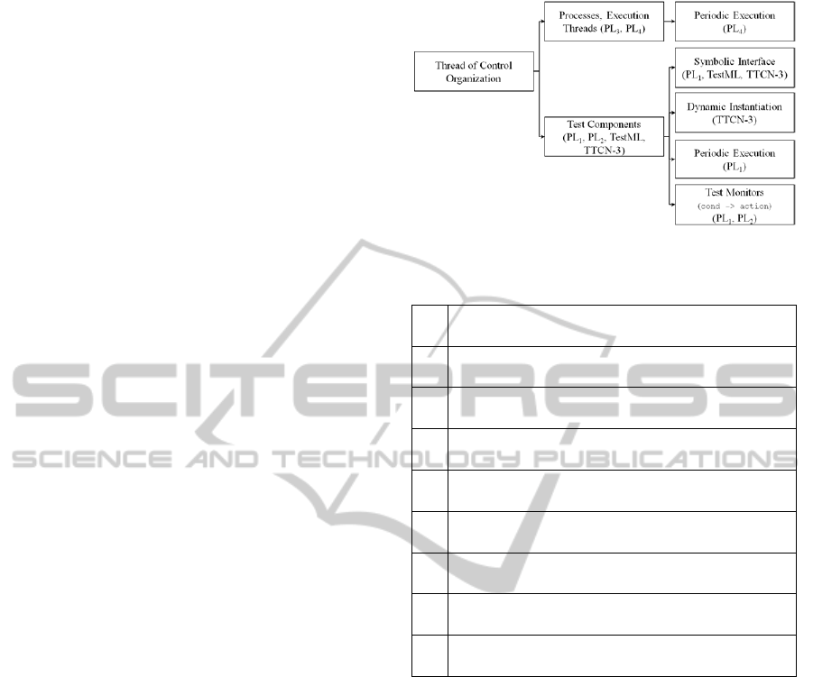
Figure 1 shows an excerpt of intra-test
organization features. For more information see
(Guduvan et al., 2012). One important concept we
identified is the concept of test component,
possessing its own execution thread. Several test
components are executed in parallel during a test.
Not all languages offer this feature, having to rely on
lower-level general-purpose multi-threading /
processing facilities. PL
1
, TestML and TTCN-3
offer the richest notion of test component with a
symbolic connection interface. This allows for
multi-instantiation and reuse of test components by
changing the connection. We also found specialized
forms of components, like periodic components (that
execute their behavior periodically, “synchronized”
with the SUT cycles) or simple components that
monitor a condition.
Regarding the test language instructions, we
found heterogeneous forms; from one language to
another, as well as within a given language. This
reflects the history of the languages, as they were
enriched progressively when demanded by the users.
Let us take the example of interactions at the level of
application parameters, like getting a value or
applying a ramp stimulation. We may have:
actions attached to ICD elements programmatic
handlers - aHndlr.getValue(), where the
handler was created using the identifier -
aHandler = getHndlr(‘id’).
actions grouped into specific toolkits that take
the identifier or handler as a parameter -
signalTlkt.ramp(‘id’, paramList),
actions taken as a parameter by a generic toolkit
- tlkt.do(‘ramp’, ‘id’).
Overall, the analysis allowed us to gain an insight
into the best existing practices, as well as the pitfalls
to avoid (such as the above heterogeneity). It
convinced us that no standard is emerging and that a
new approach would be relevant. It strongly
influenced the design of the test meta-model
underlying the proposed model-driven approach.
Table 1 shows some high-level principles, extracted
from this analysis, which guided the definition of the
test meta-model. For more information see
(Guduvan et al., 2012)
Figure 1: Intra-Test Organization Features (Excerpt).
Table 1: Some Meta-Modeling Guiding Principles.
P1
Structured view of all SUT interfaces, allowing
navigation across ICD hierarchical levels.
P2
Extension points for SUT interface types and associated
test actions.
P3
Test actions attached to ICD elements according to their
type.
P4
Inter-test organization concepts: test case, test suite and
test group.
P5
Intra-test organization concepts: test component and test
section.
P6
Different test component types: test monitor, periodic
and cycle-by-cycle test component.
P7
Test component formal interfaces for multiple
instantiation and reuse.
P8
Allowable behavior of a test component depending on
its type.
P9
Verdict management: synthesis of global verdicts from
local ones.
For example, in order to add test actions in a
controlled manner and avoid heterogeneity, the test
meta-model offers the test solution provider
predefined extension points (P2). They allow the test
solution provider to customize and maintain the test
solution. Extension points are places inside the test
meta-model where new functionalities can be added,
minimizing the risk that a user renders the meta-
model incoherent or heterogeneous when enriching
it. For access to the SUT and associated interactions,
we chose to use the structure of the ICD as an
organizing principle (P1). Test actions are
distributed at the different interface hierarchical
levels, with strong type control of which action is
available for which ICD element (P3). The meta-
model incorporates all identified test component
features (P5, P6), except the dynamic creation. The
latter was not found useful in the target domain of
application, where test architectures are static.
Conversely, feedback from engineers caused us to
include a new type of component deemed useful: the
AMeta-modelforTestsofAvionicsEmbeddedSystems
7
cycle-by-cycle component (P6), the execution of
which is “synchronized” with the execution cycles
of the SUT. For each cycle or set of cycles of the
system under test, the test component executes a
specific behavior.
In addition, the analysis of test languages also
convinced us that existing standardized test
languages used in other fields are not easily portable
to our domain. Test languages used in hardware
testing (ATLAS, ATML) target mostly structural
electronic circuitry defects that are detected by
applying electrical signals at different places in the
circuit. In contrast, the in-the-loop testing of avionic
embedded systems targets the functional logic of the
system, implemented by software components.
TTCN-3 targets mostly open-loop distributed
systems, where the asynchronous sending of a few
messages triggers the functional activity of an
otherwise quiescent system. This allows TTCN-3 to
abstract all interactions with the system under test
into a small number of core instructions: send and
receive for message-based communication, call
and reply for synchronous communication with
remote services (avionic embedded systems do not
use remote service calling). This approach does not
correspond to our industrial context, where the
system under test exhibits a cyclic behavior and
where the number of instructions is high and
dependent on the type of communication mean: the
AFDX and ARINC 429 each have their own specific
possible interactions.
4 TEST META-MODEL
We used meta-modeling as a tool for formalizing the
different test-specific concepts and their relations, as
well as obtaining access to model-driven
technologies / tools. For the definition of our test
meta-model we retained EMF Ecore as the meta-
modeling language (Eclipse Modeling). It allows
access to a number of existing free open-source tools
to produce: specialized graphical editors – with the
Graphical Modeling Framework (GMF), textual
editors – with Xtext (Xtext), model checkers – with
the Object Constraint Language (OCL), as well as
code generators – with Acceleo (Acceleo). This
aspect is important for industrial-grade application,
where tool support around a specific technology is a
determinant factor for its success or failure. Access
to these tools can allow users to rapidly develop
their own tools around the test meta-model we
propose. In the case of our demonstrator, the total
effort was of 6-9 person-months, comprising the
development of the mixed editors and their
integration within the target test platform; as well as
the definition of the automatic code generation
templates and their testing on a case study.
Currently, the test meta-model integrates a rich set
of concepts formalized within 190 EClass elements.
Their characteristics and relations are formalized
within 340 EAttribute and EReference elements.
4.1 Test Solution Customization and
Management (P1 to P3)
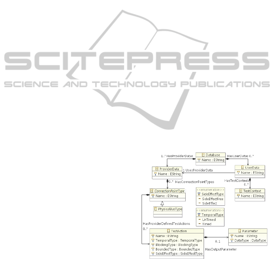
The root of the test meta-model is the Database
(Figure 2). It contains the ProviderData and
UserData, which separate the elements that are
defined by the provider of the test solution from
those defined by the test engineer. The final user
actually receives a pre-instantiated test model from
the test solution provider, where only the
ProviderData section is filled in. Its elements are
available to the final user inside the UserData
section. The test solution provider can create
different variants for its customers, as well as update
existing ones, by working only in ProviderData
section. The ProviderData provides a hierarchical
structure for the available SUT interface types and
test actions (P1). The ConnectionPointType allows
for extensions of the interface types (P2). It is also
used to assemble test actions that are common to all
ICD elements of a type (e.g., generic bus actions
plus actions specific to the AFDX bus type) (P3).
Figure 2: Separation of Concerns between ProviderData
and UserData.
Notice in Figure 2 the different EAttribute elements
possible for a TestAction. They are used by OCL
rules put on the behavior of test cases and
components, as will be discussed later on.
MODELSWARD2013-InternationalConferenceonModel-DrivenEngineeringandSoftwareDevelopment
8
4.2 High-level Structural Test
Concepts (P4, P5, P8)
The UserData contains TestContext instances. The
concept of TestContext is inspired from the one
proposed in the UML Testing Profile (UTP). When
we could, we tool inspiration from the best practices
of existing work. This was limited by the fact that
existing work does not specifically target our
industrial context and lacks the specialized concepts
we need. A TestContext serves as a container for a
collection of test cases applied to a SUT using an
architecture of test components. The context also
contains a global pool of auxiliary data and events
for inter-test component communication.
Conceptually, the TestContext is actually divided
into three levels: high-level structural elements (e.g.,
test group and suite, test case, test component), low-
level structural elements (e.g., test section, cycle of a
cycle-by-cycle component) and finally behavior
elements (e.g., repetition statement or test action
calls) (P4, P5). The allowed behavioral elements
depend on the type of structural element, for fault
avoidance purposes (P8).
The clear separation between structural and
behavior elements was also found useful for the
definition of a mixed model editor: structural
elements are described graphically, while behavioral
ones textually.
We present next the TestComponent and its low-
level structural concepts.
4.3 Low-level Structural Test Concepts
(P6, P7)
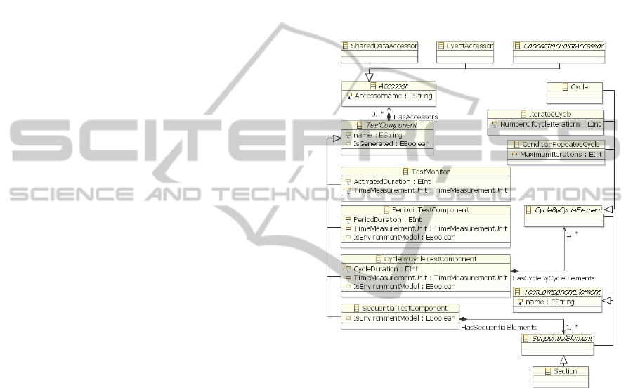
A TestComponent has its own execution flow. Four
types have been defined, depending on their
behavior (Figure 3, P6).
A TestMonitor has a simple condition->action
behavior. A SequentialTestComponent has a
behavior that is executed only once, while a
PeriodicTestComponent is executed periodically –
note the PeriodDuration. We will present the
CycleByCycleTestComponent later on.
A TestComponent can directly access the
following elements that are declared in the
TestContext: SharedData elements (for
communication), Event elements (for
synchronization) and the different interfaces of a
SystemUnderTest. For reuse, components can have a
formal interface with typed Accessor parameters
(P7). The test architecture defines the mappings for
each component instance created by a test case.
A TestComponent organizes its behavior inside
TestComponentElement containers. The internal
organization of a CycleByCycleTestComponent is
shown in Figure 3. The Cycle element includes
behavior to be executed at one cycle, the
IteractedCycle element includes behavior to be
repeated for a fixed number of cycles, while the
ConditionRepeatedCycle element includes behavior
to be repeated until a condition becomes false or the
MaximumIterations is reached. A sequence of such
elements allows the user to easily define behavior
where different test actions are applied at
consecutive system cycles.
Figure 3: TestComponent Excerpt.
Other types of components have different low-level
structural concepts. From Figure 3, a
SequentialTestComponent may have Section
elements executed sequentially, where a section
identifies a subset of behavior that is meaningful for
the test engineer (e.g., SUT initialization,
stimulation).
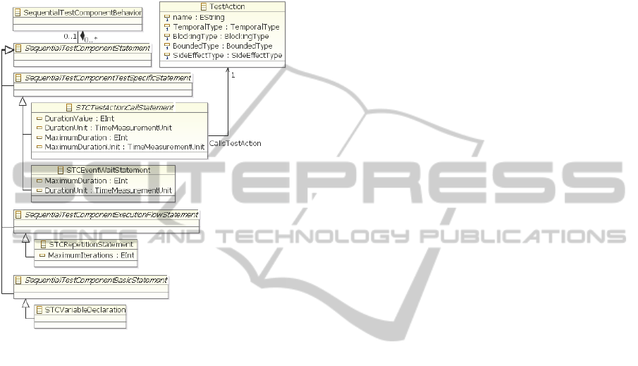
4.4 Behavioral Concepts (P8)
As illustrated by Figure 4, the behavioral level
involves:
execution flow-control instructions (e.g., the
repetition statement),
basic instructions (e.g., local variable declaration
and assignment)
test action calls (e.g., interactions with SUT).
AMeta-modelforTestsofAvionicsEmbeddedSystems
9
There is a type-based control of the allowed
behavior attached to a structural element. For
example, only TestComponent elements are in
charge of the interactions with the SUT; while the
TestCase is in charge of controlling the execution of
components. Forbidden associations are avoided by
construction or with the help of OCL checks (P8).
Figure 4: Behavioral Concepts - Focus on
SequentialTestComponent.
For example, notice in Figure 4 how the
DurationValue of a TestAction is rendered an
explicit notion inside the TestActionCallStatement,
differentiated from other parameters. This makes it
possible to perform time-related checks. For
example, we can verify that a
PeriodicTestComponent never calls a Timed
TestAction with a DurationValue higher than its
PeriodDuration. Observe also how some statements
in Figure 4 have a bounded/unbounded attribute. For
example, an EventWaitStatement can be bounded by
an optional MaximumDuration EAttribute. As only
bounded constructs are allowed in periodic and
cycle-by-cycle components, the previously optional
EAttribute is mandatory in these cases.
Other checks concern access to the global pool of
data and events offered by the context. Our approach
is to have an access policy with one producer and
potentially many consumers. A unique test
component instance is declared the owner (producer)
of a particular data or event in a test architecture.
Accesses with side-effects (e.g., setValue()) are
distinguished from those without (e.g., getValue()) -
see the EAttribute elements of a TestAction in
Figure 2. We defined OCL rules that check that the
owner is the only one making side-effect accesses.
For more information on the meta-modeling of
generic basic and execution-flow-control
instructions, we recommend the underlying meta-
model of Xbase (partial programming language
defined in Xtext) as an example. We took inspiration
from Xbase and from the grammars of existing
general-purpose programming languages when
abstracting generic basic and execution-flow-control
instructions inside the test meta-model.
4.5 Verdict Management (P9)
Verdict management was mostly absent in the
proprietary languages we analyzed. We propose a
solution borrowed from TTCN-3 (P9). The verdict
of a higher-level container (e.g., a TestCase) is
synthesized automatically, by taking the maximal
value of local verdicts of the elements it owns (e.g.,
a number of TestComponentInstance elements). The
order relation is: error > fail > inconclusive > pass >
none. We offer a TestConditionEvaluationStatement
as a syntactic facility for local verdicts of the form:
if logicalCondition then setVerdict() (see the check
instruction in the textual editor shown in Figure 5).
5 DEMONSTRATOR
A demonstrator exemplifies the usage of the test
meta-model for building test model editors and code
generation templates. The target implementation
language is a Python layer on top of the U-TEST™
integration test platform (U-TEST) (different from
the PL
1
language mentioned in Section 3, which was
based on C++). The SUT is a simplified Flight
Warning System (FWS) equipment model.
We focus here on a simple test case, inspired
from a real one. It exercises the synthesis an output
alarm for an engine fire situation, based on four
input partial alarms. This logic is validated in two
steps. First the four input alarms are activated and
the starting of the output alarm within 1 second is
verified. Secondly, two among the four input alarms
are deactivated and the stopping of the output alarm
within 10 seconds is verified.
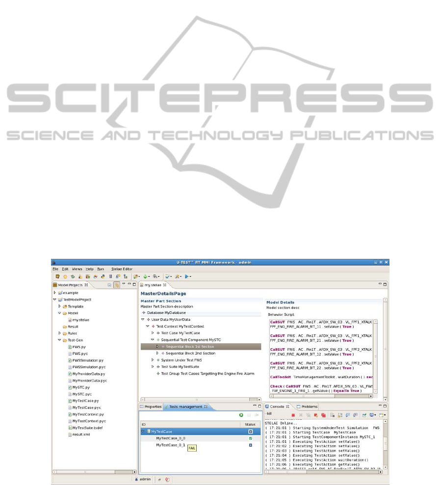
A model of this test is entered using a mixed
(graphical and textual) development environment
(Figure 5). The graphical editor on the left currently
offers dynamic contextual menus allowing the user
to manipulate the high/low-level structural elements.
The textual view (with Xtext) on the right offers
MODELSWARD2013-InternationalConferenceonModel-DrivenEngineeringandSoftwareDevelopment
10
syntax checking, text coloration, as well as auto-
completion capabilities, for the behavioral
description. Although separate, these two editors
work on a same test model instance. The textual
representation shown in Figure 5 is only one
example of concrete syntax attached to the test
models. The test solution provider can customize the
concrete syntax depending on the habits of its
clients. Moreover, a test engineer can write a test
using one concrete syntax, share it with another
colleague who can visualize it in a completely
different concrete syntax. The same is possible for
the graphical editor.
Before the automatic code generation, the test
model is validated in two ways: whether it conforms
to the underlying meta-model and whether it
respects our set of OCL checks. The code generation
uses the template-based technology with Acceleo.
Currently, an architecture of 75 templates has been
developed, implementing the test case construct and
all the test component types we identified, together
with symbolic connection interfaces for application
parameters. Implemented test actions at the
application parameter level include simple get and
set manipulations, as well as timed stimulations such
as ramp and sine. We also implemented
mathematical and logical expressions.
For this demonstration we defined a
ProviderData with the different types of SUT
interface levels for an AFDX bus, together with a
subset of associated test actions. This part is not
visible in Figure 5, as access to the ProviderData
part of the model requires authentication, not being
visible to normal users. Taking the logic of the test
case into account, the user is offered TestAction
elements for the BooleanApplicationParameterType
to get and set the various alarm parameters, as well
as a timed wait() action.
With the user role, we entered the UserData part
of the test model (visible in Figure 5). Let us first
look at the structural elements entered in the
graphical editor on the left. We defined the SUT
interfaces in a SystemUnderTest (FWS), using the
types available in the pre-instantiated model. We
defined a TestCase (MyTestCase) that starts an
instance MySTC_1 of the SequentialTestComponent
MySTC, in a new thread. The test component has its
behavior structured as follows. The 1stSection,
visible in the textual editor on the right, contains the
beginning part of the verified logic (the four input
parameters are activated and the starting of the alarm
within 1 second is verified), while the 2ndSection
contains the last part (two among the four input
parameters are deactivated and the stopping of the
alarm within 10 seconds is verified).
A number of Python scripts were generated.
They can be noticed in the left “Model Project” view
of Figure 5. After their execution in the “Console”
view, the results of the test are shown in the “Test
Management” view. The first test condition
verification (MyTestCase_0_0) returns a pass, while
the second a fail (we did this on purpose by
modifying the FWS model), the global verdict being
fail.
Figure 5: Mixed (Graphical & Textual) Test Model Development Environment.
AMeta-modelforTestsofAvionicsEmbeddedSystems
11

Once the SUT interfaces are entered, defining this
simple test model takes only a couple of minutes,
with the automatic code generation being almost
instantaneous.
6 RELATED WORK
Model-driven engineering is an active field of
research. We focus here on work addressing the use
of model-driven engineering for the development
and implementation of tests. Work addressing the
generation of abstract tests from system models
defined in formalisms such as UML (model-based
testing) is outside the scope.
Most existing work on test development
solutions uses UML for the test models. Many
projects have addressed the integration of the
standardized UML Testing Profile (UTP, 2012) and
TTCN-3 (TTCN-3, 2012). The profile is used in
(Zander et al., 2005) to produce TTCN-3 code (or
code skeletons). A meta-model for TTCN-3 can be
found in (Schieferdecker et al., 2004), later
encapsulated within the TTworkbench platform
(TTworkbench). A similar project at Motorola
(Baker and Jervis, 2007) uses the TAU tool suite
(Rational Tau). Some authors proposed their own
UML profiles. In avionics, UML-based modeling of
simulation software for MiL testing is proposed in
(Yin et al., 2009). (Hernandez et al., 2008) has a
UML profile and model transformations for web
applications testing.
One of the major difficulties we encountered was
the heterogeneity of the proprietary test languages.
From this perspective, an interesting work is
(Fischer et al., 2004), investigating meta-models for
ITU-T languages such as TTCN-3 or SDL. Its aim is
to abstract away from concrete BNF grammars and
use a set of core concepts shared by a family of
languages, provided by language experts. We share
with (Fischer et al., 2004) the concern for unification
at an abstract level. However, we did not consider
the identification of concepts as a support for
building language meta-models, but for the
definition of one test meta-model to serve as a
common front-end for writing tests, replacing the
many proprietary languages.
Other projects concern the extension of existing
test solutions to make them suitable for embedded
systems. Extensions have been proposed to TTCN-3
in (Schieferdecker et al., 2006) and (Dai et al.,
2002), although they are not yet part of the standard.
SUT environment modeling was discussed in
(Grossmann et al., 2012).
7 CONCLUSIONS
This work is part of an R&D project studying the
introduction of a model-driven approach for the
development of tests for avionics embedded
systems. We believe that the multiplicity of
implementation solutions should be addressed at a
high level, the one of language concepts and test
design models.
This paper presented the test meta-model
underlying the proposed approach. It targets in-the-
loop testing of avionics embedded systems. It was
derived from the analysis of industrial practice and
integrates a rich set of domain-specific concepts.
The test meta-model allows for customization
and maintenance of the testing solution, by
providing a clear separation between the user data
and test-solution provider data (with predefined
extension points). It also keeps a separation between
structural and behavioral elements. Structural
elements are entered using a graphical editor, while
a textual editor is offered for the behavioral part.
Still, all elements are consistently integrated, with
type-dependent restrictions for the behavior attached
to the structure. Overall, the model-driven approach
should contribute not only to homogenization at an
abstract level, but also to fault avoidance. Some
programming errors are avoided by construction, or
detected by checks performed on the model.
The chosen meta-modeling language, EMF
Ecore, gives us facilities for building model editors
and code generators. A demonstrator was presented,
using a simplified Flight Warning System as a case
study. In the current status, we can already
demonstrate the complete development of simple
and medium-complexity tests: from the definition of
test models to the automatic generation of code and
its execution on a real test platform. We plan to
improve the ergonomics of the editor, to automate
activities that are currently performed manually
(e.g., SUT interface model created by parsing an
ICD), and to further elaborate on template-based
code generation. Our goal is to reach a sufficient
maturity level for allowing industrialization of the
technology.
ACKNOWLEDGEMENTS
The authors would like to thank the following
persons for their implication in the demonstrator:
Guilhem BONNAFOUS, Mathieu GARCIA, Gilles
BALLANGER and Etienne ALLOGO.
MODELSWARD2013-InternationalConferenceonModel-DrivenEngineeringandSoftwareDevelopment
12

REFERENCES
716-1995 - IEEE Standard Test Language for All Systems
- Common/Abbreviated Test Language for All
Systems (C/ATLAS)
1671-2010 - IEEE Standard for Automatic Test Markup
Language (ATML) for Exchanging Automatic Test
Equipment and Test Information via XML
ES 201 873 - Methods for Testing and Specification
(MTS); The Testing and Test Control Notation version
3; Part 1: TTCN-3 Core Language. 2012
Thomas Stahl, Markus Voelter and Krzysztof Czarnecki.
2006. Model-Driven Software Development:
Technology, Engineering, Management. John Wiley &
Sons.
Guduvan, A., Waeselynck, H., Wiels, V., Durrieu, G.,
Schieber, M. and Fusero, Y.: Test Languages for In-
the-Loop Testing of Avionics Embedded Systems,
LAAS Report N 12151, Mars 2012, 21p.
http://homepages.laas.fr/waeselyn/Reports/TR-12151
.pdf
Aliki Ott. System Testing in the Avionics Domain. Ph. D.
Dissertation, University of Bremen, Germany, 2007
Cassidian T & S - U-Test Software, http://www.eads-
ts.com/web/products/software/utest.html
Juergen Grossmann, Ines Fey, Alexander Krupp, Mirko
Conrad, Christian Wewetzer, and Wolfgang Mueller.
2006. TestML - A Test Exchange Language for
Model-Based Testing of Embedded Software. Lecture
Notes In Computer Science, Vol. 4922. Springer-
Verlag, Berlin, Heidelberg 98-117.
DOI = http://dx.doi.org/10.1007/978-3-540-70930-5_7
Eclipse Modeling - EMFT - Home, http://
www.eclipse.org/modeling/emft/?project=ecoretools
GMF, Graphical Modeling Framework,
http://www.eclipse.org/modeling/gmp/
Xtext, http://www.eclipse.org/Xtext/
OCL, Object Constraint Language, Version 2.3.1, January
2012, http://www.omg.org/spec/OCL/2.3.1/
Acceleo, http://www.eclipse.org/acceleo/
UTP, UML Testing Profile, Version 1.1. 2012.
http://www.omg.org/spec/UTP/1.1/
J. Zander, Z. Ru Dai, I. Schieferdecker, G. Din. From
U2TP models to executable tests with TTCN-3: An
approach to model driven testing, in Proc.
international conference on testing of communicating
systems (TestCom 2005), pp. 289-303, 2005.
Ina Schieferdecker, George Din. A Meta-model for
TTCN-3. FORTE 2004 Workshops The FormEMC,
EPEW, ITM, Toledo, Spain, October 1-2, 2004.
Volume 3236 of Lecture Notes in Computer Science,
pages 366-379, Springer, 2004
TTworkbench - The Reliable Test Automation Platform,
Testing Technologies. http://www.testingtech.com/
products/ttworkbench.php
Paul Baker and Clive Jervis, Testing UML2.0 Models
Using TTCN-3 and the UML2.0 Testing Profile, Proc.
SDL 2007, LNCS 4745, Springer, pp. 86-100, 2007.
Rational Tau, IBM, http://www01.ibm.com/software
/awdtools/tau/
Yin, Y. F., Liu, B., Zhong, D. M., & Jiang, T. M. (2009).
On modeling approach for embedded real-time
software simulation testing. Journal of Systems
Engineering and Electronics, 20(2), 420-426.
Yanelis Hernandez, Tariq M. King, Jairo Pava, Peter J.
Clarke: A Meta-model to Support Regression Testing
of Web Applications. SEKE 2008: 500-505
Joachim Fischer, Michael Piefel, and Markus Scheidgen:
A Meta-Model for SDL-2000 in the Context of Meta-
Modelling ULF, SAM 2004, SDL and MSC
Workshop, Ottawa, Canada, June 2004.
Ina Schieferdecker, Eckard Bringmann and Jürgen
Großmann. 2006. Continuous TTCN-3: testing of
embedded control systems. In Proceedings of the 2006
international workshop on Software engineering
forautomotive systems (SEAS '06). ACM, New York,
NY, USA, 29-36.
DOI = http://doi.acm.org/10.1145/1138474.1138481
Zhen Ru Dai, Jens Grabowski, and Helmut Neukirchen.
2002. Timed TTCN-3 - A Real-time Extension for
TTCN-3. In Proceedings of the IFIP 14th
International Conference on Testing Communicating
Systems XIV (TestCom'02), Ina Schieferdecker,
Hartmut König, and Adam Wolisz (Eds.). Kluwer,
B.V., Deventer, The Netherlands, The Netherlands,
407-424.
Jurgen Grossmann, Philip Makedonski, Hans-Werner
Wiesbrock, Jaroslav Svacina, Ina Schieferdecker and
Jens Grabowski. Model-Based X-in-the-Loop Testing.
Model-Based Testing for Embedded Systems. CRC
Press 2011. Print ISBN: 978-1-4398-1845-9
AMeta-modelforTestsofAvionicsEmbeddedSystems
13
