
Synthesizing Decentralized Components from
a Variant of Live Sequence Charts
Dirk Fahland
1
and Amir Kantor
2
1
Eindhoven University of Technology, Eindhoven, The Netherlands
2
Weizmann Institute of Science, Rehovot, Israel
Keywords:
Live Sequence Charts, Scenarios, Decentralized Synthesis, Petri Nets, Partially Ordered Runs.
Abstract:
Live sequence charts (LSC) is a visual, executable, language for the modeling of reactive systems. Each chart
depicts an inter-object scenario arising in the modeled system, partitioned into two: a monitored prechart, and
a main chart. Despite the intuitive use of the language, complications arise when one wants to implement
an LSC specification with decentralized components. In this paper, we introduce a variant of LSC, called
distributed LSC (dLSC), which is targeted for the modeling and synthesis of decentralized systems, composed
of several interacting components. While LSCs are commonly interpreted in terms of an interleaved execution
of the scenarios in a sequential run, dLSCs employ partially ordered runs. We investigate the expressive
power of dLSC compared to an established model of concurrent systems, namely, Petri nets, and show that
dLSCs are, computationally, strictly more expressive than low-level Petri nets and subsumed by higher-level
Petri nets. Specifically, we present an algorithm that synthesizes, given a dLSC specification, an equivalent
token history net, which can serve as an executable implementation of the specification. Most importantly, the
implementation is decentralized — components can be automatically extracted from the net. The synthesis of
Petri-net components from a dLSC specification is supported by a tool.
1 INTRODUCTION
Scenario-based formalisms, such as message sequence
charts (MSC) (ITU, 1996) and live sequence charts
(LSC) (Harel and Marelly, 2003), are actively used to
describe the behavior of complex systems in an intu-
itive way, particularly at earlier stages of system design.
Scenarios visually describe interactions among com-
ponents and objects of the system. This inter-object
behavior is aligned along time-lines, corresponding
explicitly to the runs of the modeled system. In that
respect, scenarios are dual to the intra-object perspec-
tive taken in traditional system-models such as state-
charts (Harel, 1987) and Petri nets (Reisig, 1985). In
the latter, the system is described in terms of states
and actions of each object in the system. The latter are
useful as blueprints for implementing the system in
hardware or software, but they are generally hard to de-
vise. Thus, a notable challenge is to synthesize from a
specification in the form of a set of scenarios, a system-
model, called an implementation of the specification,
which behaves as specified in the scenarios.
A particularly challenging class of systems to de-
sign are concurrent systems (Ben-Ari, 2006). A con-
current system involves several interrelated compo-
nents that are executed simultaneously so that control
is decentralized among the components. Such systems
are very common, in particular when concurrency is
dictated by the underlying architecture that provides
no central control. Examples for such systems are web-
services executed over the Internet, and embedded sys-
tems composed of autonomous controllers. Moreover,
real-life processes, e.g., business processes, carried
out by several autonomous persons or units, can be
modeled and analyzed as concurrent systems.
In this paper, we address scenario-based modeling
of concurrent systems, and the problem of synthesiz-
ing such systems from the specifications. Scenarios,
which present interactions between components in a
partially ordered structure, can naturally describe ex-
ecutions of concurrent systems. In fact, MSCs are
extensively used in industry to describe sample inter-
actions in concurrent systems and distributed protocols.
Yet, MSCs are essentially too weak to capture the logic
that underlies most systems (Damm and Harel, 2001).
LSC enriches the scenarios of MSC, mainly by being
multi-modal, and makes them expressive enough to
become a fully-fledged model for the system, expres-
25
Fahland D. and Kantor A..
Synthesizing Decentralized Components from a Variant of Live Sequence Charts.
DOI: 10.5220/0004320500250038
In Proceedings of the 1st International Conference on Model-Driven Engineering and Software Development (MODELSWARD-2013), pages 25-38
ISBN: 978-989-8565-42-6
Copyright
c
2013 SCITEPRESS (Science and Technology Publications, Lda.)

sively comparable to intra-object behavioral models.
However, the language of LSC, in its present form,
is not well suited for the modeling of concurrent,
decentralized, systems. First, play-out (Harel and
Marelly, 2003), the executable semantics of LSC, de-
fines a central controller that implements the system
as a whole. Moreover, regardless of how play-out
is defined, it is shown in (Bontemps and Schobbens,
2007) that without additional coordination some LSC
specifications cannot be distributed into components.
As we discuss in Sect. 2, the standard interpretation
of LSC (Harel and Marelly, 2003) results in implicit
dependencies between the different parts of a scenario,
which arise throughout any typical specification. For
systems which can be operated by a single controller,
this raises no difficulty. However, in decentralized
architectures, such dependencies require more interac-
tion between the components than specified.
If we were to use LSC, or any other formalism,
for specifying concurrent systems, the behavior that
can be specified in that formalism must be such that
it can be exhibited by decentralized components. In
this context, it is significant to impose a restriction
on the components, that they coordinate and interact
with each other merely as described in the specification.
Otherwise, components are not as autonomous, and the
system is more centralized than intended. Moreover,
as in typical LSC specifications, additional interactions
may result in a significant efficiency overhead.
With the intention to support the modeling of con-
current systems, we introduce a variation on the se-
mantics of LSC. It is applied on a central fragment
of the language, which includes scenarios partitioned
into a prechart and a main chart (see Sect. 2). Instead
of the traditional interpretation, presented in terms of
interleaved sequential runs, we interpret LSC speci-
fications on the basis of partially ordered runs (Pratt,
1986); i.e., traces of executions in which events are
partially ordered. In such a semantic domain, also
known as a true-concurrency semantic domain, we
adopt LSC’s prechart/main-chart distinction. As runs
are partially ordered, they convey more information
than interleaved runs — regarding the causal dependen-
cies between the events. Here, as scenarios themselves
are partially ordered, a fragment of a scenario can be
identified with a matching sub-structure in the run.
Changing the semantic domain results in a sim-
ple variant of the language, which we refer to as dis-
tributed live sequence charts (dLSC). dLSC avoids
implicit dependencies between separate parts of a sce-
nario, and is thus, we believe, well suited for the mod-
eling of concurrent systems. Moreover, as partially
ordered runs directly correspond to the visual struc-
ture of charts, our interpretation is simple and compre-
hensible, and has a rigorous mathematical basis. We
demonstrate the language and its use with a case study.
We investigate the expressive power of dLSC with
respect to a common model of concurrent systems,
namely, Petri nets (Reisig, 1985). We show that dLSC
specifications are, effectively, strictly more expressive
than low-level Petri nets in the form of place/transition
nets (Reisig, 1985). However, they do not exceed
the expressive power of high-level nets; dLSC spec-
ifications are subsumed by the class of token history
nets (Van Hee et al., 2008).
We present an algorithm that synthesizes, for any
given dLSC specification
S
, an equivalent token his-
tory net
N
S
. A token history net, being a particular
kind of a coloured Petri net (Jensen, 1987), is an ex-
ecutable model, and thus may serve as an implemen-
tation of the specification. Moreover, and most im-
portantly, the implementation is decentralized — the
components specified in
S
can be extracted from the re-
sulting net
N
S
, and, for a large class of specifications,
no additional interaction between the components is
involved. The synthesis of Petri-net components from
a dLSC specification is supported by a prototype tool.
The paper is structured as follows. In Sect. 2, the
semantics of LSC is discussed more closely. In Sect. 3,
we introduce the variant of distributed LSC through an
example, whereas a formal representation of the for-
malism and its semantics is given in the appendix.
In Sect. 4, we investigate the expressive power of
dLSC. Our technique to synthesize system-models
from dLSC specifications and to extract decentralized
components from them is presented in Sect. 5 and 6,
as well as our prototype tool. We discuss related work
in Sect. 7, and conclude in Sect. 8.
2 FROM LSCs TO DISTRIBUTED
LSCs
In Fig. 1(a), we illustrate a live sequence chart
L
a
. In
the chart, there are three vertical lines, called
lifelines
,
which correspond to three objects: A, B, and C. The
interactions between the objects are depicted by four
arrows, labeled by a, b, c, and d, which designate
events or messages. Time passes along lifelines from
top to bottom, which determines the order between
the events (namely, a through d in that exact order).
Events in LSCs are, in general, partially ordered.
L
a
is
divided into two: a prechart, depicted inside a dashed
hexagon (containing event a), and a main chart, de-
picted inside a solid rectangle (containing events b
through d). The prechart and the main chart are of
two complementary modalities: monitored versus exe-
cute. The prechart is monitored; i.e., it is matched at
MODELSWARD2013-InternationalConferenceonModel-DrivenEngineeringandSoftwareDevelopment
26

(a) (b)
Figure 1: A live sequence chart L
a
.
run-time against the events that are executed, but does
not yield new behavior. The main chart, in contrast,
supplements runs with new behavior. If and when the
prechart is met, the main chart is enabled and thus
executed. Accordingly, in
L
a
, if and when event a
occurs, events b, c, and d are executed.
1
The common semantics of LSC (see, e.g., (Harel
and Marelly, 2003)) is based on an interleaved execu-
tion of LSCs; i.e, a sequential run is constructed from
the interleaving of partial order scenarios. An LSC is
one consolidated structure, in the following sense: if
any of the events that appear in the chart happens to
occur out of the order prescribed by the chart, the sce-
nario is violated, and should be aborted. Consider, for
example, the chart
L
a
presented in Fig. 1(a), describ-
ing interactions between three objects, A, B, and C. If
event a occurs for some reason (perhaps due to some
other chart) after a, b, and c have all occurred, but
before d, then C should abort the scenario without exe-
cuting d. In order to achieve this kind of behavior, C
must be aware of occurrences of a. Thus, if the system
is to be implemented by decentralized components,
C must be notified of the executions of a (even those
coming from outside the present chart) one way or
another. There are many such implicit dependencies
in
L
a
alone. E.g., such a dependency arises also be-
tween b and d, so that C must be aware of executions
of b, and A must be aware of executions of d.
If the modeled system is to be implemented in a
decentralized architecture, such dependencies intro-
duce an essential complication, as the implementa-
tion would require additional unspecified interactions
between the components. Moreover, this results in
communication overheads and excessive run-time syn-
1
There is another multi-modal distinction in the language
of LSC (Harel and Marelly, 2003), between cold behaviors,
which may happen in the system (possible), and hot behav-
iors, which must happen (mandatory). In
L
a
, all events are
cold (possible), which is designated by blue dashed arrows,
and thus may be discarded in the presence of other, conflict-
ing, alternatives. The following observations are independent
of the hot/cold distinction.
(a) (b)
(c) (d)
(e)
Figure 2: Distributed LSCs of an emergency management
procedure.
chronization among the components. In this paper
we establish the use of LSC, and specifically the lan-
guage’s prechart/main-chart distinction, in a semantic
domain that is more suited to the modeling of concur-
rent systems. The resulting formalism is referred to
as distributed LSC (dLSC). In this paper we address a
basic, central, fragment of the language of LSC. We
consider charts, each partitioned into a prechart and a
main chart, containing cold events.
3 THE VISUAL FORMALISM OF
DISTRIBUTED LSC
We introduce distributed LSCs in the context of an
example, which involves concurrently operating com-
ponents. We model the behavior of an emergency
management procedure. The procedure involves one
or more medics, providing first-aid treatment, a clinic,
and an Emergency Management System (EMS), which
keeps track of pending emergencies and mediates be-
tween the medics and the clinic.
SynthesizingDecentralizedComponentsfromaVariantofLiveSequenceCharts
27

3.1 Scenarios
A dLSC specification is a finite set of dLSCs (and an
initial run) which together describe the system’s be-
havior. Fig. 2(c) shows an illustrative dLSC of the
procedure, denoted by
L
3
. A dLSC is a partial order-
ing of events; events are drawn as rectangles, and the
ordering of events is indicated by arrows. The horizon-
tal dashed line divides
L
3
into a monitored prechart
(denoting the precondition that enables
L
3
) and a main
chart (denoting the behavior contributed by
L
3
, which
is to be executed once the prechart is met). The vertical
lifelines in
L
3
are used to graphically align events of
the same component but have no formal meaning.
The prechart of
L
3
consists of two unordered
events, labeled EMS.alert and M
i
.ready. Throughout
the specification, the events of the
i
th
medic are pre-
fixed by M
i
(for different concrete values of
i
), those of
the clinic are prefixed by C, and those of the EMS by
EMS. Event EMS.alert represents a notification from
the EMS of a pending emergency. Event M
i
.ready
designates a notification by the medic that he has be-
come ready to handle emergencies. If and when the
EMS notifies of a pending emergency, and the medic
is ready, the execution may continue according to the
main chart as follows.
The main chart of
L
3
contains five events, start-
ing with M
i
.go, which indicates that the medic travels
to the location of the emergency. Then, the medic
transports the patient to the clinic (M
i
.transp), and,
concurrently, provides first-aid treatment (M
i
.treat
B
).
After both events, the clinic enrolls the newly arrived
patient (C.enroll), and the medic becomes ready to
handle following emergencies (M
i
.ready).
Another dLSC,
L
4
depicted in Fig. 2(d), describes
medical treatment at the clinic. Its prechart is com-
prised of three events, two of which are ordered: the
clinic enrolls the arrival of a patient (event C.enroll)
after
receiving treatment by the medic (M
i
.treat
B
), and,
in addition, the resources of the clinic are set and ready
(C.ready). When the prechart is met, the execution
continues as indicated in the main chart: the patient
receives treatment at the clinic (C.treat), after which
the clinic’s resources are ready for the next patient
(C.ready).
The specification includes three more charts.
dLSC
L
2
of Fig. 2(b) captures situations in which
first-aid treatment by the medic is enough (M
i
.treat
A
)
after which the medic is available again (and the pa-
tient need not be brought to the clinic). dLSCs
L
2
and
L
3
have the same prechart. As we consider all events
to be cold (possible), we understand such scenarios
as alternatives: whenever the prechart of
L
2
and
L
3
is met, the execution continues according to either
L
2
or L
3
.
dLSC
L
1
of Fig. 2(a) captures the arrival of emer-
gency calls to the EMS. Whenever the EMS is ready
(EMS.ready), a new emergency may arrive, result-
ing in two independent events: the EMS alerts the
medics of a pending emergency (EMS.alert), and the
EMS becomes ready again to receive more emergen-
cies (EMS.ready). Finally, a specification contains
an initial run that describes how the procedure be-
gins. It is depicted in Fig. 2(e) and is denoted by
R
0
.
In our example,
R
0
includes four unordered (indepen-
dent) events: the events EMS.ready, two events labeled
M
1
.ready and M
2
.ready (assuming the process involves
two medics; any number of medics is supported), and
the event C.ready.
3.2 Semantics
Syntactically, a dLSCs is just an LSC drawn in a
slightly more abstract form. For instance, LSC
L
a
of Fig. 1(a) can be represented as in Fig. 1(b). Where
dLSCs and LSCs actually differ is in their interpreta-
tion. Instead of LSC’s interleaved semantics, we in-
terpret dLSCs on the basis of Pratt’s partially ordered
runs (Pratt, 1986), a common framework to describe
the behavior of concurrent systems.
Partially Ordered Runs.
Fig. 3(a) shows a partially
ordered run
ρ
1
. It consists of 9 events (drawn as rectan-
gles) that are labeled and partially ordered according
to the directed arcs (the dashed vertical lines align
events graphically but have no formal meaning). A
partially ordered run captures the causal dependen-
cies between events — an event occurs after all its
predecessors have occurred. For instance, in Fig. 3(a),
events EMS.ready, M
1
.ready, M
2
.ready and C.ready
can all occur in the beginning, i.e., they are mutually
independent. Once EMS.ready occurred, EMS.alert
and the second EMS.ready event occur; M
1
.go can
only occur after both, M
1
.ready and EMS.alert have
occurred.
A partially ordered run
ρ
corresponds to a set of se-
quential runs, each being an interleaving of the events
in
ρ
that is consistent with the partial order in
ρ
. Such
an interleaving corresponds to what a global observer
overlooking the execution might see.
dLSCs Describe Partially Ordered Runs.
As indi-
vidual scenarios are themselves fragments of partially
ordered runs, the latter seems a natural candidate for
the semantic domain. When executions are represented
as partially ordered runs, the ordering of events in a
scenario directly carries over to the runs, and individ-
ual scenarios can be recognized inside the run. This
perspective suggests an alternative way to interpret
MODELSWARD2013-InternationalConferenceonModel-DrivenEngineeringandSoftwareDevelopment
28

(a) ρ
1
(b) ρ
2
(c) ρ
3
Figure 3: Runs of the emergency management procedure.
LSCs.
The behavior induced by a dLSC specification
S
may be briefly described as follows. The specification
is executed starting with the initial, partially ordered,
run (
R
0
in our example). A prechart of some dLSC
L
in
S
matches the end of a run whenever the events of
the prechart occur at the end of the run — in the same
order. In this case, the events in the main chart of
L
are
locally concatenated at the end of the run. With such
concatenations, partially ordered runs are augmented,
possibly ad infinitum. The exact formal semantics are
given in the appendix. In the following, we illustrate
this semantics by our running example.
The partially ordered run in Fig. 3(a), which we
denote by
ρ
1
, is an example of an execution of the
emergency management procedure. It is obtained as
follows. Starting with the initial run
R
0
, the prechart
of
L
1
is met, and so its main chart is concatenated.
This results, in particular, in the creation of the event
EMS.alert. Then, the precharts of both
L
2
and
L
3
are
met, so either one may be concatenated.
ρ
1
is the
result of concatenating
L
2
. The other possibility, of
concatenating
L
3
, appears in run
ρ
2
of Fig. 3(b). Runs
ρ
1
and
ρ
2
are alternatives. In
ρ
2
, the concatenation of
L
3
results, in particular, in the occurrence of the event
C.enroll. Then, the prechart of
L
4
is met, and so the
main chart of L
4
is also concatenated.
A slightly more involved execution is
ρ
3
of
Fig. 3(c). It contains two EMS.alert events. The first
alert is handled by
M
1
according to dLSC
L
2
, and
the second alert is handled by
M
2
according to dLSCs
L
3
and
L
4
. Runs
ρ
1
,
ρ
2
, and
ρ
3
can be continued,
possibly ad infinitum.
Difference from Classical LSC.
Observe that the ac-
tivities of the two medics in
ρ
3
are unordered, reflect-
ing the fact that the two medics operate independently.
In classical LSC (Harel and Marelly, 2003), this con-
current behavior would not have been obtained, as the
second EMS.alert event (that triggers
L
3
) would vio-
late
L
2
of Fig. 2(b) as long as
L
2
is not completed.
This illustrates the fundamental difference between
dLSC, which is interpreted on the basis of partially
ordered runs, and classical LSC.
3.3 The Extended Example
In order to illustrate other aspects in the semantics of
distributed LSC, we incrementally extend the emer-
gency management procedure with three additional
dLSCs.
L
5
, depicted in Fig. 4(a), describes another
alternative to
L
2
and
L
3
: a medic reaching the pa-
tient may realize that the clinic needs to prepare for
the incoming patient. The medic notifies the EMS of
the incoming patient (M
i
.notify), which in turn noti-
fies the clinic (EMS.notify). According to dLSC
L
6
of Fig. 4(b), the clinic prepares for the arrival of the
patient (C.prepare), and then waits for the patient
(C.wait4), concurrently to the other duties of the clinic
(due to C.ready). After the patient has enrolled in
the clinic, he is treated according to dLSC
L
7
(see
Fig. 4(c)).
An execution of the extended specifications is de-
picted in Fig. 5. The run, denoted
ρ
4
, is similar to
ρ
3
of
SynthesizingDecentralizedComponentsfromaVariantofLiveSequenceCharts
29
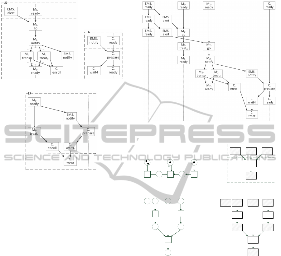
(a) (b)
(c)
Figure 4: Extending the emergency management procedure.
Fig. 3(c), but the second medical emergency is treated
according to
L
5
. After the concatenation of
L
5
and
L
6
the prechart of
L
7
is matched, while the prechart of
L
4
is not; only the main chart of
L
7
can be added, after
the events C.enroll and C.wait4. dLSC
L
7
illustrates
the expressive power of precharts to describe behavior
across components. dLSC
L
4
and
L
7
both include the
event C.enroll in their precharts, but it is preceded by
different events (namely, M
i
.treat
B
in
L
4
and M
i
.treat
C
in
L
7
). Therefore, the precharts reflect different sit-
uations. Moreover, the prechart of
L
7
states that the
event C.enroll corresponds to the same patient waited
for by C.wait4 because of the joint predecessor event
M
i
.notify.
4 EXPRESSIVE POWER
We just introduced dLSC, which interprets the core
concepts of LSC in the context of partially ordered
runs. In this section, we discuss whether this core
language and interpretation are sufficiently expressive
to describe decentralized systems.
dLSC Subsumes Petri Nets.
Distributed LSCs can
be seen to subsume low-level Petri nets in the form of
place/transition nets (PTN) (Reisig, 1985; Peterson,
Figure 5: A run
ρ
4
of the extended emergency management
procedure.
p1
t1
p3
p2
t2
p5
t3
p4
(a) N
b
p4p3p2
t2
L
t2
p3
(b)
t2
p3
p2
t1
p1 p5p3
p4
t3
p1
(c) A run of N
b
p4p2
t2
p3
p3 p5p1
t1 t3
p1
(d) A run of S
N
b
Figure 6: Translating a place/transition net into a dLSC
specification.
1977). PTNs are an abstract model for the flow of
control and information in systems, particularly con-
current and decentralized systems.
A PTN consists of places
P
(drawn as circles)
and transitions
T
(drawn as rectangles) that are con-
nected by arcs from places to transitions and from
transitions to places; see, for example, PTN
N
b
de-
picted in Fig. 6(a). The global state of the net is given
by a marking which puts in each place a nonnegative
number of tokens; a PTN has a dedicated initial mark-
ing. Given a marking, a transition
t
is enabled if each
place with an arc to
t
has a token. If
t
is enabled, it
may fire, which results in a new marking obtained by
removing a token from each place with an arc going
MODELSWARD2013-InternationalConferenceonModel-DrivenEngineeringandSoftwareDevelopment
30

to
t
and putting a token on each place with an arc
coming from
t
. These notions give rise to both an
interleaved semantics, presented in terms of sequen-
tial runs, and a true-concurrency semantics in terms
of partially ordered runs that is consistent with the
interleaved semantics (Goltz and Reisig, 1983). The
partially ordered runs of a Petri net can be constructed
by local continuations — each firing of a transition is
recorded as a local continuation. Figure 6(c) shows a
partially ordered run of PTN
N
b
of Fig. 6(a) as follows:
transition
t
1
occurred, consuming a token from
p
1
and
producing a token on
p
2
;
t
3
occurred concurrently to
t
1
, consuming from
p
5
and producing on
p
4
; transition
t
2
occurred after
t
1
and
t
3
, consuming from
p
2
,
p
3
and
p
4
and producing on p
3
.
Next, we show that dLSC are expressive enough to
specify any place/transition Petri net. Given a PTN
N
,
one can construct an equivalent dLSC specification
S
N
.
We take
Σ := T ∪P
to be the set of actions in our spec-
ification, which includes both transitions and places.
Places can be considered as auxiliary actions, and can
be abstracted away from the runs induced by the spec-
ification, in case one is only interested in the events
that are due to the firing of transitions.
For each transition
t ∈ T
, we construct a dLSC
L
t
as follows (see Fig. 6(b), illustrating the dLSC cor-
responding to transition
t
2
of
N
b
). The prechart of
L
t
contains the input places of
t
as events. There is
no ordering between the events in the prechart. The
main chart of
L
t
begins with the event
t
, after which
the output places of
t
are included with no ordering
between them. The dLSC specification corresponding
to the net
N
contains one dLSC
L
t
for each transition
t
of
N
, and an initial run
R
0
, where
R
0
contains for
each place
p
of
N
as many
p
-labeled events as there
are tokens on
p
in the initial marking, with no ordering
between the events. This construction also applies to
place/transition nets with arc weights, by duplicating
events representing places according to the weights.
It can be shown that the set of runs of
S
N
is iso-
morphic to the set of partial order Petri-net runs of
N
.
The idea is to represent the latter on the basis of local
continuations. Each continuation rule for construct-
ing the Petri-net runs, corresponds to a dLSC in
S
N
.
Fig. 6(c) illustrates the Petri-net run of
N
b
, starting
from the initial marking, while Fig. 6(d) depicts the
corresponding run of the dLSC specification S
N
b
.
Strictly more Expressive than Petri Nets.
The con-
verse proposition, that each dLSC specification can
be effectively translated into an equivalent PTN, does
not hold. Intuitively, PTNs cannot mimic the enabling
condition expressed by precharts with a complex struc-
ture. The enabling of a Petri net transition depends
only on the availability of tokens in its preplaces and
nothing else; the enabling of a dLSC can depend on
several past events and their causal ordering. The proof
that establishes the greater expressive power of dLSC
compared to PTN is a variation on a similar proof
in (Fahland, 2010). It shows that any instance of Post’s
correspondence problem (PCP) can be expressed as
a dLSC specification, such that a particular event oc-
curs if and only if the PCP instance has a solution.
In PTN, the problem of deciding whether a particular
event can occur is decidable, whereas PCP is unde-
cidable. Therefore, there is no algorithm to translate
dLSC specifications into equivalent PTNs.
5 SYNTHESIZING SYSTEMS
Section 4 shows that distributed LSC, our interpreta-
tion of LSC in the context of partially ordered runs,
allows to specify the behavior of a large class of con-
current systems. In the remainder of the paper, we ad-
dress the following problem, which may be referred to
as the decentralized synthesis problem: given a dLSC
specification
S
(i.e., a set of dLSCs, in which events
are assigned to components, and an initial run), syn-
thesize an implementation consisting of decentralized
components, in a suitable system-model formalism,
which behave and interact exactly as specified in S.
Section 4 shows that this problem is not trivial,
and that the class of simple place/transition nets is
not expressive enough to capture the behavior spec-
ified in dLSC specifications. In order to solve the
decentralized synthesis problem, we use a slight ex-
tension of place/transitions nets, called token history
nets (Van Hee et al., 2008), to represent the synthesized
implementation. In the present section, we show how
to effectively synthesize from a given dLSC specifica-
tion
S
an equivalent token history net
N
S
. Then, indi-
vidual components can be easily extracted from
N
S
,
which is discussed in Sect. 6.
The synthesis of
N
S
is carried out as follows.
Events of
S
are translated into transitions in
N
S
, and
the partial order between them is enforced in
N
S
through Petri-net places. To capture that the occur-
rence of some event of
S
depends on its preceding
events, we use the fact that tokens in
N
S
record their
own history, in terms of the transitions that they have
passed. A transition in
N
S
will only be enabled by to-
kens with the correct history. We first present the class
of token history nets, and then define the synthesis
of N
S
from S.
5.1 Token History Nets
This part gives an informal introduction to token his-
SynthesizingDecentralizedComponentsfromaVariantofLiveSequenceCharts
31

tory nets; the formal definitions are given in (Fahland
and Kantor, 2012). A token history Petri net
(THPN) (Van Hee et al., 2007; Van Hee et al., 2008) is
a Petri net in which transitions are labeled with actions
Σ
or with
τ 6∈ Σ
;
Σ
are observable actions (which will
represent the actions in a dLSC specification), while
τ
is a silent (or, unobservable) action. The main dif-
ference from place/transition nets is that each token
of a THPN is a partially ordered run as discussed in
Sect. 3.2, representing the history of transition firings
that have led it to its current place. A firing of a transi-
tion extends the histories of the tokens involved.
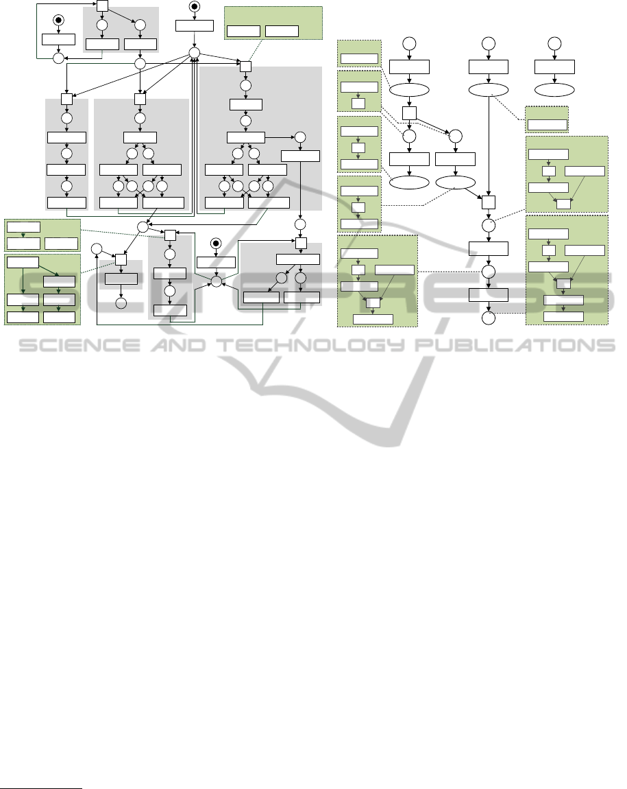
Figure 7(a) shows a token history net. As usual, a
circle represents a place, a rectangle represents a tran-
sition, and transition labels are inscribed. Moreover,
each transition has a guard in the form of a token his-
tory (shown for the transitions that go by the names
L
2
to
L
5
, and
L
7
). Intuitively, a transition is only enabled
if the token histories in its pre-places together end with
the token history in the guard.
We illustrate the semantics of THPNs with a par-
tially ordered run (Goltz and Reisig, 1983)
ρ
of the
THPN
N
of Fig. 7(a). Run
ρ
is shown in Fig. 7(b) as
an acyclic labeled Petri net: each place of
ρ
(called
a condition) with label
p
represents a token history
on the place
p
; a transition
e
of
ρ
(called an event),
with label
t
, represents a firing of transition
t
of
N
;
the pre-places (post-places) of
e
represent the token
histories consumed (produced) by t.
For instance, in Fig. 7(b), condition
b
3
denotes that
the place
E.ready
is marked with history
h
0
(consist-
ing only of event
E.ready
). In this situation, transition
L
1
is enabled. Event
e
3
denotes the firing of
L
1
, which
consumes
h
0
from
E.ready
and produces
h
1
(
h
0
ex-
tended with the occurrence of the silent transition
L
1
)
on both
p
3
and
p
4
, as represented by conditions
b
6
and
b
7
in
ρ
. Event
e
5
denotes the firing of the transition la-
beled
E.alert
(the one consuming from
p
4
), which con-
sumes
h
1
from
p
4
, and produces
h
3
on place
E.alert
as represented by condition
b
9
. The run of Fig. 7(b)
shows how the token histories are built up event by
event, eventually joining several token histories into
one at event
e
6
. Note that transition
L
2
is only enabled
because the union of histories
h
3
and
h
7
ends with
the guard of
L
2
. Guards in a THPN can also be more
complex such as the guard of
L
7
which requires token
histories on
C.enroll
and
C.wait4
to have a joint event
M
1
.notify.
5.2 Translating Specifications into
Token History Nets
In the execution of a THPN, each token history records
the preceding events as a partially ordered run. This
allows us to capture the semantics of dLSC specifica-
tions with token history nets. Fig. 7(a), for instance,
depicts the result of the translation of the specifica-
tion of Sect. 3 into a THPN (to avoid cluttering the
figures, we show only one of the medics). The formal
translation is included in (Fahland and Kantor, 2012).
Translating the Specification.
We translate a dLSC
specification
S = hD, R
0
i
over actions
Σ
(where
D
is
a set of dLSCs and
R
0
is the initial run) into an equiv-
alent THPN
N
S
over
Σ
. We first translate each chart
L ∈ D
into a net
N
L
, and then, compose the resulting
nets to form the net
N
S
of the entire specification. The
different
N
L
’s are connected via shared places: for
each action
a
that appears maximal in some main chart
of a chart
L ∈ D
there is a shared place
p
a
, on which
N
L
produces. For a chart
L
0
∈ D
in which an event
labeled
a
appears maximal in the prechart,
N
L
0
will
consume from p
a
.
Translating Individual Charts.
Each dLSC
L
in the
specification induces a net
N
L
. For each main-chart
event
e
of
L
,
N
L
contains a transition
t
e
that gets the
same label as
e
. The partial order of
L
’s main chart is
encoded by places. In addition, each transition
t
e
of
N
L
gets a guard that ensures that
t
e
is only enabled if
the token history produced by
t
e
ends with the history
of
e
in
L
, i.e., the events preceding
e
in
L
. The initial
run R
0
is translated into a net N
R
0
in the same way.
In Fig. 7(a), the result of translating the main charts
of the specification of Sect. 3 as described above is
shown inside the shaded boxes. For instance, consid-
ering dLSC
L
2
, the net contains a transition labeled
M
1
.go for the minimal event in the main chart of
L
2
,
preceded by the activation place
p
5
. The last event in
L
2
, labeled M
1
.ready, produces on the shared place
M
1
.ready. The subnet
N
R
0
of the initial run is scat-
tered throughout between the other subnets; its activa-
tion places are p
0
, p
1
, and p
2
.
The transitions of
N
L
that represent the minimal
events in the main chart of
L
shall only be enabled
when all the maximal events in
L
’s prechart have oc-
curred. We formalize this by a main-chart activation
transition
t
L
with label
τ
(unobservable);
t
L
consumes
from the shared places corresponding to the maximal
events in
L
’s prechart and produces on places that en-
able the minimal events in
L
’s main chart. In addition,
t
L
has a guard that enables
t
L
only if the prechart of
L
has occurred. A firing of
t
L
will not be visible in
the resulting token history as
t
L
has a label
τ
. E.g., in
Fig. 7(a), the
τ
-transition
L
2
is the activation transition
of dLSC
L
2
of Fig. 2(b). When checking whether the
token histories consumed by a transition
t
satisfy the
guard of t, τ-labeled events in the tokens are ignored.
The synthesized net
N
S
exhibits the same behav-
MODELSWARD2013-InternationalConferenceonModel-DrivenEngineeringandSoftwareDevelopment
32
E.alertE.ready
M
1
.go
M
1
.ready C.enroll
t
p
3
p
4
M
1
.transp
M
1
.treat
B
L
1
E.ready
L
5
E.alert
M
1
.ready
E.ready
p
0
M
1
.ready
p
1
L
3
M
1
.ready C.enroll
t
M
1
.notify
M
1
.go
E.notify
E.notify
M
1
.go
M
1
.treat
A
M
1
.ready
t
p
5
p
6
p
7
t
L
2
M
1
.transp
M
1
.treat
C
C.enroll
C.ready
C.ready
p
2
t
L
6
C.ready
C.prepare
C.wait4
C.wait4
t
C.treat
L
7
C.treat
C.treat
C.ready
t
L
4
C.enroll
C.enroll
M
1
.treat
C
C.prepare
M
1
.notify
E.notify
C.wait4
guard (L
7
)
C.enroll
M
1
.treat
B
C.ready
guard (L
4
)
E.alert
M
1
.ready
guard (L
2,
L
3,
L
5
)
(a)
L
1
E.alertE.ready
E.ready
E.alert
M
1
.go
M
1
.treat
A
L
2
E.ready
p
3
p
4
M
1
.ready
p
5
p
6
p
7
C.ready
E.ready
E.alert
M
1
.ready
M
1
.go
b
3
b
4
e
3
E.ready
E.ready
E.ready
b
6
b
7
b
8
e
4
b
9
e
5
b
11
b
10
b
12
e
6
e
7
e
8
b
5
M
1
.treat
A
h
0
:
h
2
:
h
3
:
h
4
:
t
E.ready
E.alert
t
t
t
E.ready
E.alert
M
1
.ready
M
1
.go
t
t
h
9
:
E.ready
h
1
:
t
M
1
.ready
h
7
:
E.ready
E.alert
M
1
.ready
h
8
:
t
t
e
0
E.ready
p
0
b
0
e
1
M
1
.ready
p
1
b
1
e
2
C.ready
p
2
b
2
(b)
Figure 7: A token history net synthesized from dLSCs L
1
–L
7
(left), and a run ρ of this net (right).
ior that is specified in
S
. More precisely, the partial
order runs of
N
S
are the same as (i.e., isomorphic to)
those of
S
, after the events of
τ
-labeled transitions
are abstracted away from the net’s runs. That is, the
specified behavior is refined by unobservable actions
(more on this in Sect. 6).
2
6 EXTRACTING COMPONENTS
In Sect. 5, we introduced a technique to synthesize
from a dLSC specification
S
, a THPN
N
S
with the
same behavior. In this section, we proceed and extract
decentralized Petri-net components from
N
S
. This
would complete the path from a scenario-based model,
namely, a dLSC specification
S
, to Petri-net models of
the components that implement it.
6.1 Components
As in our running example, we assume that in the
specification each action is performed by a particular
component, which is denoted explicitly. Specifically,
we assume a finite set of components
C
, such that each
2
As specified above, token histories can grow indefinitely.
However, guards of transitions only consider the more recent
events. Thus, the length of token histories can be bounded
by the longest chart in the specification, by truncating (e.g.,
in each transition) older events.
action of
S
is of the form
c.e
for some component
c ∈ C and an event name e.
Each transition
t
in
N
S
is then either labeled by
an action
c.e
, or it is a
τ
-labeled transition that cap-
tures the activation of the main chart of some dLSC
L
(denoted by
t
L
in Sect. 5.2). In the former case,
t
is
associated with the component
c
that performs the un-
derlying action. In the latter case,
t
must be assigned
to a component; this is an important matter that we
address in Sect. 6.2. Assigning transitions to compo-
nents naturally induces a decomposition of the net
N
S
into Petri-net components.
For each
c ∈ C
, a Petri-net component
N
c
is de-
fined to be the subnet of
N
S
containing the transitions
assigned to
c
, denoted by
T
c
, the places
P
c
that are
directly connected to the transitions in
T
c
, and the
arcs between
T
c
and
P
c
as appears in
N
S
. This stan-
dard construction is formalized in (Fahland and Kantor,
2012). A place
p
belonging to more than one compo-
nent is an interface place; otherwise, p is internal.
According to such decomposition, when the com-
ponents are put together they yield the original net
N
S
.
Therefore, when executed, the components exhibit pre-
cisely the behavior of the net
N
S
. As discussed in
Sect. 5, this behavior matches that prescribed in dLSC
specification S.
Considering our running example, actions are pre-
fixed by a component name: either E (the EMS), M
i
(the
i
th
medic), or C (the clinic). Extracting compo-
nents from the synthesized net of Fig. 7(a) as described
SynthesizingDecentralizedComponentsfromaVariantofLiveSequenceCharts
33

init
ready
ready
L2
go
treat_A
ready
L3
go
treat_B
transport
ready
L5
go
notify
transport
treat_C
ready
alert
init
ready
ready
L1
ready
alert
notify
notify
init
ready
enroll
ready
enroll
L4
treat
ready
enroll
L6
prepare
ready
wait4
L7
treat
Medic
1
Clinic
EMS
Figure 8: The result of synthesizing components from
dLSCs L1–L7.
(a) (b)
(c)
Figure 9: Runs including unobservable actions.
(a) (b)
(c)
Figure 10: Unobservable actions abstracted away.
above yields the components shown in Fig. 8. This
figure was obtained using our tool SAM, which is de-
scribed in the following.
6.2 Interactions between Components
When considering decentralized synthesis from spec-
ifications, the latter must impose restrictions on how
components interact with each other. Without any lim-
itation in that respect, one could construct components
that interact arbitrarily. This would undermine the
autonomous nature of the components, and lend the
problem not well-defined.
In a partially ordered run, interaction is made ex-
plicit through the causal dependencies recorded in the
run. If an implementation presents exactly the same
partially ordered runs as in the specification, then by
definition the components interact exactly as speci-
fied (and exhibit no additional interaction). This is
the case for the net
N
S
synthesized from
S
, up to the
τ
-labeled transitions of
N
S
that express the activation
of a main chart (see Sect. 5). In the following, we
discuss how such unobservable actions influence the
interaction between components. Then, we assign the
τ
-labeled transitions of
N
S
to components so that the
latter interact as specified in S.
Unobservable Actions.
Compare the partially or-
dered runs of Fig. 9, which include
τ
-labeled events,
with the corresponding runs of Fig. 10 in which the
τ
-labeled events are abstracted away and the causal
dependencies between the observable events remain
intact. The runs in Fig. 10, which record only observ-
able events, correspond to specified behavior, while
the runs of Fig. 9 correspond to the runs of an im-
plementation containing also unobservable transitions.
In the runs, each event, including the unobservable
events, is associated with a particular component.
A direct causal dependency between events of dif-
ferent components gives rise to an interaction between
the components. E.g., in Fig. 10(a), as event c1.e
directly causes event c3.f, there is an underlying inter-
action between the components. Depending on how
τ
-
labeled actions are performed, the interaction scheme
may change: in Fig. 9(a),
c
1
and
c
3
no longer interact
with each other; rather, through the
τ
-labeled event
of component
c
2
,
c
1
interacts with
c
2
and
c
2
with
c
3
.
This is exactly the situation that must be avoided when
a decentralized implementation contains unobservable
actions that refine the specified behavior.
Figures 9(b) and 9(c) show situations in which the
refined behavior of the implementation presents the
same interaction scheme as in the specified behavior.
In Fig. 9(b) and 10(b), all events belong to the same
component, so no interaction is present. In Fig. 9(c),
there is an interaction between
c
1
and
c
2
, which is
also the case in Fig. 10(c) (multiple arrows from one
event in
c
1
to multiple events in the same component
c
2
count as one interaction). These two cases illustrate
MODELSWARD2013-InternationalConferenceonModel-DrivenEngineeringandSoftwareDevelopment
34

sufficient conditions in which unobservable events do
not change the interaction scheme: a
τ
-labeled event
x
is termed pre-internal (post-internal) if all direct suc-
cessor (predecessors) events of
x
are performed by
the component performing
x
;
x
is
internal
if it is pre-
and post-internal. In Fig. 9(b), the
τ
-labeled event is
internal, in Fig. 9(c) it is pre-internal, and in Fig. 9(a)
it is neither.
In the runs of the implementation, an unobserv-
able event that is pre- or post-internal does not change
the interaction scheme between the components com-
pared to the specification. Thus, when assigning the
τ
-labeled transitions of
N
S
to components, we have to
make sure they only yield pre- or post-internal events.
A Petri-net transition
t
yields only pre-internal events
if all post-places (having an arc from
t
) are internal
places, since the succeeding transitions belong to the
same component as
t
; similarly,
t
yields only post-
internal events if all pre-places are internal.
Assigning Activation Transitions.
There is a class of
specifications for which there is a natural way to assign
activation transitions to components. A dLSC
L
is
called local choice if all the minimal events in its main
chart are of the same component
c ∈ C
. Intuitively, in
this case, only component
c
is involved when the main
chart begins, and thus the choice for an activation of
the chart can be made locally in component
c
. For a
local choice dLSC
L
, the activation transition of
L
is
assigned to component c as well. A specification S is
said to be local choice if all the dLSCs in
S
are local
choice. E.g., the specification of our running example,
as one may easily verify, is local choice.
In local choice specifications, when activation tran-
sitions are assigned to components as indicated above,
any occurrence of a
τ
-labeled action in the run is pre-
internal. This can be deduced from the structure of
N
S
,
as the post-places of each activation transition are in-
ternal. Therefore, the
τ
-labled transitions in
N
S
do
not change the interaction scheme between the compo-
nents compared to the specification.
As for non-local choice charts, activation transi-
tions need to be explicitly assigned by the modeler.
Then, although the observable behavior is precisely as
indicated in
S
, interactions that are not made explicit
in the specification may be introduced. These can be
made explicit by refining the specification to become
local choice.
Tool Support.
Our technique for synthesizing Petri-
net components from dLSC specifications is imple-
mented in a prototype tool called SAM. The tool takes
as input a dLSC specification in a simple textual syn-
tax, describing each dLSC’s prechart and main chart as
a partial order of events. Additionally, components can
Figure 11: A CPN Tools model of three components synthe-
sized by SAM.
be specified as sets of event names. SAM produces a
token history net with extracted components as a CPN
Tools model (Jensen et al., 2007; Ratzer et al., 2003).
CPN Tools implements the general class of coloured
Petri nets (Jensen, 1987), which supports defining
datatypes for token histories, and can represent the fir-
ing rule of a THPN with operations on tokens. Fig. 11
shows the components appearing in Fig. 8 within CPN
Tools. This allows to simulate and analyze the spec-
ification and the resulting components using the full
grown functionality of CPN Tools. SAM is available
at http://www.win.tue.nl/∼dfahland/tools/sam/.
7 RELATED WORK
As discussed in Sect. 2, dLSC builds on ideas from
the language of LSC (Harel and Marelly, 2003), and
implements them in a semantic domain that is more di-
rectly related to concurrent systems, based on partially
ordered runs. The change in the semantic domain al-
lows to identify scenarios with patterns that explicitly
appear in the constructed run. This contrasts with LSC,
which identifies scenarios with their interleavings.
In LSC, whether two enabled charts can be exe-
cuted concurrently depends on the identity of their
events; that is, whether each can be executed with-
out violating the other. In the presence of violations,
the charts may become alternatives (in case of cold
main-chart events). In dLSC, in contrast, causality is
recorded in the run: two charts are executed concur-
rently if they are enabled at two causally independent
parts of the run, and they are alternatives if they are
enabled at overlapping (or identical) parts of the run.
Thus, the semantics of dLSC corresponds to that of
LSC whenever violations of charts coincide with the
charts being enabled at the same location of the run.
The semantics of dLSC somewhat resembles that
of the existential, conditional, interpretation of LSC
in (Sibay et al., 2008), which demands that whenever
SynthesizingDecentralizedComponentsfromaVariantofLiveSequenceCharts
35

a run ends with a prechart of an LSC, there exists
a run that continues with the main chart. In dLSC,
however, all possibilities to continue are induced by the
specification, and progress is assumed whenever there
is an enabled main chart.
3
Moreover, again, dLSC
employs composition of partial orders whereas (Sibay
et al., 2008) interprets LSCs over sequential runs.
Distributed LSCs are closely related to
oclets (Fahland, 2009; Fahland, 2010), a
scenario-based formalism that employs LSC’s
prechart/
main-chart
distinction in terms of Petri nets
and their partially ordered runs. dLSC can be seen as
an adaptation of oclets in a context that is purely event-
based. This significantly simplifies the formalism, and
yet oclets’ Petri-net places can be represented in dLSC
by events. Moreover, in dLSC, as in LSC, a main chart
is completely synchronized after the prechart. This
eliminates implied scenarios (Uchitel et al., 2001),
i.e., additional behavior that is not explicitly specified,
which may occur in oclets. The framework of oclets
also allows to extract decentralized components from
a specification (Fahland, 2010), but it requires a
different method that cannot take all specifications
as input, and has exponential worst-case complexity,
unlike the complete, polynomial, method proposed in
this paper.
Synthesis of systems and decentralized compo-
nents from scenario-based specifications is a well-
known problem, with many contributions; (Liang et al.,
2006) provides an extensive survey. Most approaches
consider (H)MSCs or UML Sequence Diagrams as
input, and translate the specification into statecharts or
Petri nets somewhat similarly to our technique (Liang
et al., 2006), or through behavioral synthesis (Uchitel
et al., 2001; Bergenthum et al., 2009). Moreover, cen-
tralized synthesis from LSC has been studied, which
succeeds by structural translations to statecharts (Harel
and Kugler, 2002), or through game-based synthesis
techniques (Harel and Segall, 2012). However, in all
cases, synthesis introduces either non-specified behav-
ior (implied scenarios), or centralized synchronization
between the events that makes the extraction of de-
centralized components impossible. Our synthesis
technique makes synchronization information part of
the exchanged messages by means of token histories,
which effectively prohibits implied scenarios, and, for
a large class of specifications, limits the interactions
among components to those specified in the dLSCs.
3
One can slightly generalize the definition of dLSC to
also allow for charts for which, when enabled, progress is
not assumed. The synthesis algorithm, with trivial changes,
would still apply.
8 CONCLUSIONS
In this paper, we take a fresh look at an essential frag-
ment of live sequence charts (LSC) and provide a se-
mantics in terms of partially ordered runs by means
of simple scenario composition. This variant of LSC,
called distributed LSC (dLSC), has sufficient expres-
sive power for specifying concurrent systems: effec-
tively, it is strictly more expressive than classical Petri
nets. We also provide a technique to synthesize, from
any dLSC specification, an implementation in the class
of token history nets (THPN). Decentralized compo-
nents can be easily extracted from the THPN. The
approach has polynomial time and space complexity
and is implemented in a tool, which extracts a CPN
Tools model of the components.
While the CPN Tools model can be used for simu-
lation and analysis, or as a blueprint for implementing
the components in code, automatic code generation is
an interesting open issue. As for other future work,
one may extend dLSC with a notion of data, such as
from algebraic specifications; we believe our synthesis
technique still applies, as coloured Petri nets, which
support data manipulation, could be similarly synthe-
sized. Also, operations on dLSC specifications, such
as scenario (de-)composition and refinement, are of
interest. They would permit to systematically develop
and reason on complex dLSC specifications.
ACKNOWLEDGEMENTS
We thank David Harel for his helpful comments on this
work. The research was supported in part by the John
von Neumann Minerva Center for the Development of
Reactive Systems at the Weizmann Institute of Science,
and by an Advanced Research Grant to David Harel
from the European Research Council (ERC) under the
European Community’s FP7 Programme.
REFERENCES
Ben-Ari, M. (2006). Principles of Concurrent and Dis-
tributed Programming. Addison-Wesley, second edi-
tion.
Bergenthum, R., Desel, J., Mauser, S., and Lorenz, R. (2009).
Synthesis of Petri Nets from Term Based Representa-
tions of Infinite Partial Languages. Fundam. Inform.,
95(1):187–217.
Bontemps, Y. and Schobbens, P.-Y. (2007). The computa-
tional complexity of scenario-based agent verification
and design. Journal of Applied Logic, 5(2):252 – 276.
Damm, W. and Harel, D. (2001). LSCs: Breathing Life into
MODELSWARD2013-InternationalConferenceonModel-DrivenEngineeringandSoftwareDevelopment
36

Message Sequence Charts. J. on Formal Methods in
System Design, 19(1):45–80.
Fahland, D. (2009). Oclets - Scenario-Based Modeling with
Petri Nets. In ATPN’09, volume 5606 of LNCS, pages
223–242. Springer.
Fahland, D. (2010). From Scenarios to Compo-
nents. PhD thesis, Humboldt University of Berlin.
http://repository.tue.nl/685341.
Fahland, D. and Kantor, A. (2012). Synthesizing decentral-
ized components from a variant of live sequence charts.
Technical report. http://www.win.tue.nl/
∼
dfahland/
tools/sam/dlsc synthesis tr.pdf.
Goltz, U. and Reisig, W. (1983). Processes of
Place/Transition-Nets. In ICALP’83, volume 154 of
LNCS, pages 264–277. Springer.
Harel, D. (1987). Statecharts: A visual formalism for com-
plex systems. Sci. Comput. Program., 8(3):231–274.
Harel, D. and Kugler, H. (2002). Synthesizing State-Based
Object Systems from LSC Specifications. Int. J. of
Foundations of Computer Science, 13(1):5–51.
Harel, D. and Marelly, R. (2003). Come, Let’s Play:
Scenario-Based Programming Using LSCs and the
Play-Engine. Springer.
Harel, D. and Segall, I. (2012). Synthesis from scenario-
based specifications. Journal of Computer and System
Sciences, 78(3):970 – 980.
ITU (1996). International Telecommunication Union Rec-
ommendation Z.120: Message Sequence Charts. Tech-
nical report.
Jensen, K. (1987). Coloured Petri nets. In Petri Nets: Central
Models and Their Properties, volume 254 of LNCS,
pages 248–299. Springer.
Jensen, K., Kristensen, L., and Wells, L. (2007). Coloured
Petri nets and CPN Tools for modelling and valida-
tion of concurrent systems. International Journal on
Software Tools for Technology Transfer (STTT), 9:213–
254.
Liang, H., Dingel, J., and Diskin, Z. (2006). A Compara-
tive Survey of Scenario-Based to State-Based Model
Synthesis Approaches. In SCESM ’06, pages 5–12,
ACM.
Peterson, J. L. (1977). Petri nets. ACM Comput. Surv.,
9(3):223–252.
Pratt, V. (1986). Modeling concurrency with partial orders.
Int. J. Parallel Program., 15(1):33–71.
Ratzer, A., Wells, L., Lassen, H., Laursen, M., Qvortrup,
J., Stissing, M., Westergaard, M., Christensen, S., and
Jensen, K. (2003). CPN Tools for editing, simulating,
and analysing coloured Petri nets. In ATPN 2003,
volume 2679 of LNCS, pages 450–462. Springer.
Reisig, W. (1985). Petri Nets: An Introduction. Springer-
Verlag New York, Inc., New York, NY, USA.
Sibay, G., Uchitel, S., and Braberman, V. A. (2008). Existen-
tial live sequence charts revisited. In ICSE’08, pages
41–50. ACM.
Uchitel, S., Kramer, J., and Magee, J. (2001). Detecting
Implied Scenarios in Message Sequence Chart Specifi-
cations. SIGSOFT Soft. Eng. Notes, 26(5):74–82.
Van Hee, K., Serebrenik, A., and Sidorova, N. (2008). Token
history Petri nets. Fundam. Inf., 85(1-4):219–234.
Van Hee, K., Serebrenik, A., Sidorova, N., and Van
Der Aalst, W. (2007). History-dependent Petri nets.
In ATPN’07, volume 4546 of LNCS, pages 164–183.
Springer.
APPENDIX
This appendix presents the formal semantics of dis-
tributed LSC. In the following we assume a set
Σ
of
actions. It includes names (or, labels) for all the events
that one wishes to refer to in a specification.
Labeled Partial Orders.
We begin with some prelim-
inary definitions. A labeled partial order (lpo) is a
tuple
l = hE, <, λi
, where
E
is a (possibly infinite)
set of events,
< ⊆ (E × E)
is a strict partial order re-
lation on
E
(i.e., irreflexive and transitive),
λ : E → Σ
is a labeling function, and, furthermore, for any event
x ∈ E
, the set
{y ∈ E : y ≤ x}
is finite. The last
property is included to restrict the form of lpo’s so that
they correspond to realizable traces of executions. We
write x ≤ y, iff x < y or x = y, for all x, y ∈ E.
Let
l = hE, <, λi
be an lpo. For any
A ⊆ E
, the
restriction of
l
to
A
is defined by
l|
A
= hA, < ∩ (A ×
A), λ|
A
i
, which is again an lpo. Let
l
0
= hE
0
, <
0
, λ
0
i
be another lpo.
ϕ : E → E
0
is an isomorphism from
l
onto
l
0
, denoted
l
∼
=
ϕ
l
0
, if
ϕ
is a one-to-one function
from
E
onto
E
0
, for any events
x, y ∈ E
holds
x < y
iff
ϕ(x) <
0
ϕ(y)
, and
λ
0
◦ ϕ = λ
.
l
is isomorphic to
l
0
,
denoted
l
∼
=
l
0
, if there is
ϕ
such that
l
∼
=
ϕ
l
0
.
l
is said
to be finite (resp., empty) if E is finite (resp., empty).
We write
max(l)
(reps.,
min(l)
) for the maximal
(resp., minimal) events in
E
. Given a finite
A ⊆ E
, we
say that
A
is a maximal dense set in
l
if
max(l|
A
) ⊆
max(l)
, and for any
x, y ∈ A
and
z ∈ E
, if
x <
z < y
then
z ∈ A
. Given such
A
and another lpo
l
0
= hE
0
, <
0
, λ
0
i
such that
E ∩ E
0
= ∅
, the local
concatenation of
l
0
after
A
in
l
, is defined by
l[A] →
l
0
= hE ∪ E
0
, < ∪ <
0
∪ ({x ∈ E : ∃y ∈ A : x ≤
y} × E
0
), λ ∪ λ
0
i
. It is easy to verify that it is again
an lpo. As a special case, the (global) concatenation
of l
0
after l is defined by l →l
0
= l[E]→ l
0
.
Abstract Syntax of Distributed LSC.
A distributed
LSC (dLSC) is a tuple
L = hl
p
, l
m
i
, where
l
p
and
l
m
are finite nonempty lpo’s.
l
p
is called the prechart of
L
,
and
l
m
is called the main chart of
L
. As we assume
complete synchronization between the main chart and
the prechart, we technically separate the chart into
two lpo’s. A dLSC specification consists of a tuple
S = hD, R
0
i
, where
D
is a finite set of dLSCs, and
R
0
is a finite lpo called the initial run.
Semantics of Distributed LSC.
Given an lpo
l =
hE, <, λi
and a dLSC
L = hl
p
, l
m
i
, we first define the
SynthesizingDecentralizedComponentsfromaVariantofLiveSequenceCharts
37

set of all continuations of
l
according to
L
, which is
denoted by
lB
L
. Put
l
m
= hE
m
, <
m
, λ
m
i
, and, with-
out loss of generality, assume that
E ∩ E
m
= ∅
(we
may always take
l
0
m
∼
=
l
m
satisfying this constraint).
Then,
lB
L
is the set of lpo’s of the form
l[A] → l
m
,
where
A ⊆ E
is a finite maximal dense set in
l
such
that
l|
A
∼
=
l
p
. Moreover, given a set
D
of dLSCs, the
set of all continuations of
l
according to the charts
in D is defined by lB
D
=
S
L∈D
l B
L
.
Given a dLSC specification
S = hD, R
0
i
, a con-
struction sequence for
S
is a sequence of lpo’s
ρ
with
domain
0 < D ≤ N
(i.e.,
D
is either the set
N
of
all natural numbers, or a natural number
n > 0
, in
the sense that
D = n = {i ∈ N : i < n}
), sat-
isfying the following:
ρ
0
= R
0
, and for all
i ∈ D
such that
i + 1 ∈ D
holds
ρ
i+1
∈ ρ
i
B
D
. For each
i ∈ D
, put
ρ
i
= hE
i
, <
i
, λ
i
i
. Then, the value of
ρ
is defined to be the lpo corresponding to the limit
of the sequence, which can be formally defined by
val(ρ) =
S
i∈D
E
i
,
S
i∈D
<
i
,
S
i∈D
λ
i
.
It is easy to verify that
val(ρ)
is, in turn, a (pos-
sibly infinite) lpo, and that if
D
is finite then
val(ρ)
is the last lpo in the sequence. The construction se-
quence
ρ
is said to be final if also
val(ρ)B
D
= ∅
.
The (denotational) semantics of a dLSC specifica-
tion
S
is an lpo language defined by
L(S) = {val(ρ) :
ρ is a final construction sequence for S}.
MODELSWARD2013-InternationalConferenceonModel-DrivenEngineeringandSoftwareDevelopment
38
