Systematic Development of Control Designs via Formal Refinement
Manoranjan Satpathy
1
, Colin Snook
2
, Silky Arora
1
, S. Ramesh
1
and Michael Butler
2
1
General Motors Global R &D, International Tech Park (ITPL), Bangalore - 560066, India
2
School of Electronics & Computer Science, University of Southampton, Highfield SO17 1BJ, U.K.
Keywords:
Refinement based Development, Discrete Controllers, Simulink/Stateflow, Event-B.
Abstract:
The Simulink/Stateflow (SL/SF) modeling framework is widely used in industry for the development of control
applications. However, such models are not amenable to formal reasoning. Controllers can also be designed
using formal specification languages. Such designs can be formally verified, but the models do not explicitly
represent control or data flow information. In this paper, we discuss RRM diagrams (RRMDs), a new mod-
elling notation which incorporates the benefits of these two formalisms. RRMDs are graphical formal models
and they also support incremental formal development. We have used synchronising state machines to encode
RRMDs. We have also developed a prototype tool which translates RRMDs automatically to SL/SF designs.
1 INTRODUCTION
The SL/SF modeling framework is widely used in in-
dustry for the development of control applications. Its
advantages are: (a) a model being graphical is bet-
ter understood to engineers, and (b) a model being
executable eliminates many design level bugs. The
disadvantages are: (a) the modelling language does
not have a formal semantics and hence models are not
amenable to formal reasoning, (b) models are directly
created from requirements, this is a big step and er-
rors are likely to creep in, and (c) validation can only
be done a posteriori.
Controllers can alternatively be built using formal
specification languages like Event-B (Abrial, 2010).
The advantages are that (a) formal languages support
incremental design, and (b) any design step can be
verified as and when it is introduced. The disadvan-
tages are that (a) the languages are text-based, and so
the intuition behind a model is not explicit, and (c) the
models do not explicitly represent control or data flow
information which is counter-intuitive to a modelling
engineer.
In this paper, we discuss RRM diagrams
(RRMDs) which takes the advantages of both the
above formalisms. Models as RRMDs are graphi-
cal; this formalism supports incremental feature aug-
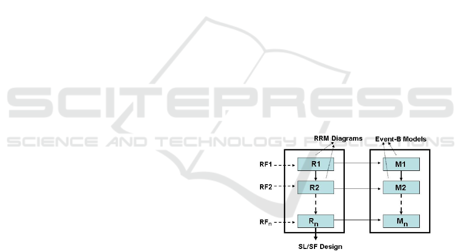
mentation and design. Figure 1 outlines the overall
development process using RRMDs. We consider a
fragment of certain requirements and build a RRMD,
say R1. This RRMD has an equivalent representa-
tion in Event-B, say M1. M1 is checked for consis-
tency using tool support. Next some more require-
Figure 1: The Overall Development Process.
ments are selected and R1 is extended (or refined)
to obtain RRMD R2. Let M2 be the Event-B repre-
sentation of R2; the refinement relationship between
M1 and M2 is verified using tool support. Like this
RRMDs – and so their Event-B models – are refined
until all requirements are incorporated. Ambiguities
and missing requirements are discovered in the pro-
cess. From the final RRMD, a SL/SF design can be
auto-generated, which we can claim to be correct-by-
construction. The main contributions of our paper are:
• Formulation of RRMDs as a graphical formal
modelling notation for developing control de-
signs.
• Use of the UML-B tool (Snook and Butler, 2006;
Snook and Butler, 2008) for encoding and animat-
ing RRMDs. The tool makes it possible to derive
Event-B models automatically from the RRM di-
agrams.
• Implementation of a translator which automati-
cally derives SL/SF designs from RRM diagrams.
143
Satpathy M., Snook C., Arora S., Ramesh S. and Butler M..
Systematic Development of Control Designs via Formal Refinement.
DOI: 10.5220/0004321001430148
In Proceedings of the 1st International Conference on Model-Driven Engineering and Software Development (MODELSWARD-2013), pages 143-148
ISBN: 978-989-8565-42-6
Copyright
c
2013 SCITEPRESS (Science and Technology Publications, Lda.)
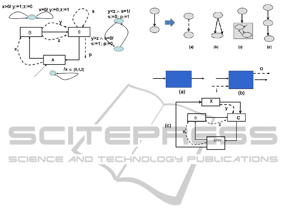
Figure 2: An RRM Diagram; C is a state holding block.
2 EVENT-B AND UML-B
The Event-B method is a formal development method
for modelling and development of distributed sys-
tems. An Event-B model consists of state variables
and invariants. In addition, there are events, each has
a guard and an action. The state variables are first ini-
tialised. Thereafter, one of the enabled events is se-
lected non-deterministically for execution. This con-
tinues as long as there are enabled events. That the
events preserve the model invariants can be checked
using tool support. An abstract model can be refined;
the refinement relationship between the abstract and
the concrete models can be checked using tool sup-
port. Further details can be found in (Abrial, 2010).
A RRMD has an equivalent representation in Event-
B; hence RRMDs get the benefit of the sound theory
and tool support of Event-B.
UML-B is a visual ‘front-end’ for Event-B and in-
cludes a state machine diagram editor. Tool support
for UML-B is provided by a plug-in to the Rodin plat-
form (Abrial et al., 2010). State machines may be re-
fined by adding nested state machines and can be an-
imated via a plug-in that utilises the Pro-B (Leuschel
and Butler, 2008) model checker and animator. We
will encode our RRMDs as UML-B models.
3 RRM DIAGRAMS
Figure 2 shows an RRM diagram, which consists of
blocks and connectors. Connectors are of two kinds:
control flow and data flow edges. In the figure, they
have been respectively shown as solid and dashed
lines. A control flow edge determines a block execu-
tion order, and a labelled data flow means the source
block computes the value of the labelled variable and
the target block uses it. Within a block, some compu-
tation is performed which is represented as a state ma-
chine; each transition has a guard and an action. Be-
Figure 3: Refinement of RRMD blocks.
Figure 4: Closing of open inputs and outputs.
fore a RRMD is made to execute, all variables in it are
initialized. There are 3 computations blocks identified
by A,B and C in Figure 2. A is the start block from
which computation starts. The control flow edges sig-
nify that B is computed after A, C is after B, and A is
after C and so on.
The state machines for the respective blocks are
as shown in the figure. When a block starts execution,
one of the enabled transitions is executed. Within a
state machine, a sequence of transitions executes till
there is no enabled transition. In such a situation,
control moves to the next block. In the figure, the
lone transition in block A assigns a non-deterministic
value (from the set {0, 1, 2}) to variable x; next, the
state machine finishes execution and control moves
to block B. There are additional flags which disable
the state machine of A and enables the transition(s) in
block B; in the figure, they have not been shown to
avoid clutter. In block B, either of the transitions is
executed which uses variable x and produces output
variables y and z. Next block B finishes execution –
flag variables ensure this – and control moves to block
C. Block C uses y and z and produces output variables
p and s. Variable s is produced as well as consumed
(in the next cycle) by block C, in this sense this is
a state-holding block, the dashed self-loop signifies
that. p is an open output, not yet used by any other
block, possibly, a latter refinement would use it.
3.1 Refinement of an RRMD
Refinement of an RRMD involves (a) refinement of
MODELSWARD2013-InternationalConferenceonModel-DrivenEngineeringandSoftwareDevelopment
144
block state machines, (b) closing of open inputs and
outputs, and (c) sequencing of parallel control.
Refinement of State Machines: A refinement of a
block state machine can be any of (a) strengthening
of a transition action, (b) parallel splitting of a transi-
tion (c) sequential splitting of a transition, and (c) cre-
ation of sub-states and lifting of the transitions at the
parent level to the sub-state level. In Figure 3, (a) rep-
resents strengthening of a transition action, (b) shows
the case splitting of a single transition into a number
of parallel transitions, (c) shows creation of sub-states
and transitions within a state, and (e) shows sequential
splitting of a transition; the first transition produces a
value and the second one uses it. We generate Event-
B models from RRMDs. What refinement steps we
perform at the RRM level, it is checked that they are
meaningful in the context of Event-B.
Handling of open inputs and outputs: State machine
refinement of a RRMD block may result in creation of
new state variables; they will be represented as open
inputs and outputs; see Figure 4(b). An open input
can be any of (i) an environmental input, (ii) the input
is already produced by another block, or (iii) this in-
put is not created anywhere. Our aim is to build con-
trol applications, so, we assume in an RRMD, there
is a special block representing the environment, say
ENV. If the open input is from the environment then
this is closed by making it an output of ENV. If the
open input is an output of another block, then this in-
put is closed by connecting it by a data flow edge to
this block. If the open input is not from the environ-
ment and it is not yet produced by any of the blocks,
this has to be an internal input, and it would be com-
puted in the subsequent modelling steps. So we create
a new block which generates this open input. Refer to
Figure 4(c) in which the open input y has been closed
by creating a new block X parallel to the existing con-
trol, block X gives a non-deterministic value to y. The
parallel control path is created between ENV and the
block which requires this input. Note that the non-
determinism in block X will be refined at a later stage.
Sequencing of Parallel Control: Two parallel control
paths would mean the two paths can be executed in
arbitrary order. So sequencing them can be a refine-
ment step. In Figure 4(c), blocks B and X are in two
parallel control paths; they can be made sequential
depending on the data dependency between them.
4 DESIGN USING RRMDs
For developing control applications, we make certain
assumptions: (a) the plant, user commands, sensors
and actuators are abstracted by a special RRM block
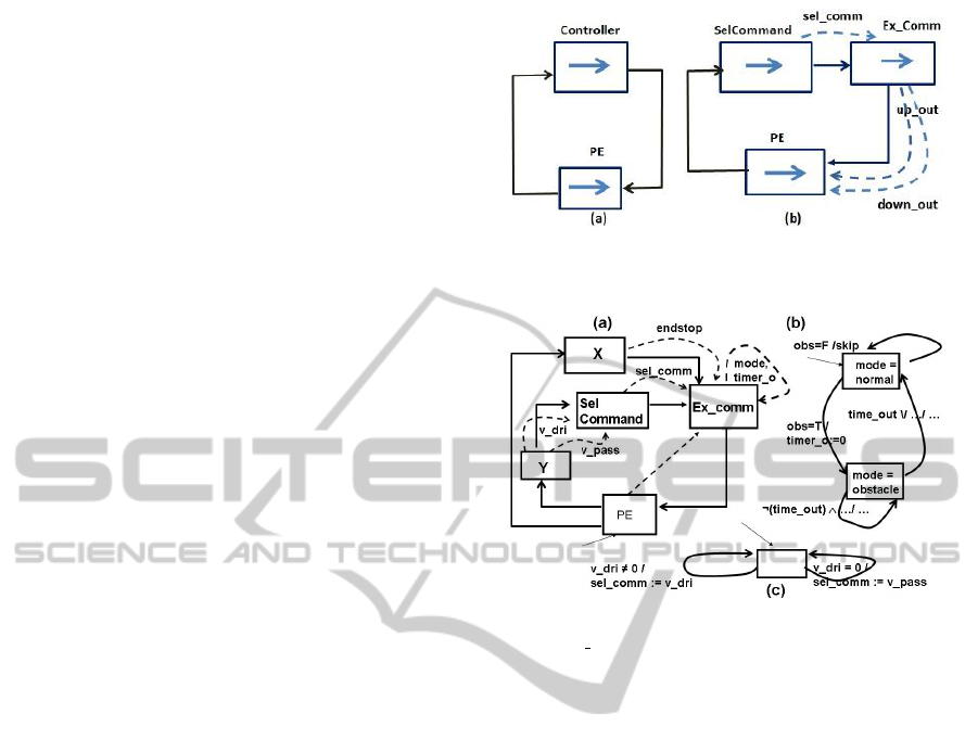
Figure 5: (a) The initial RRMD, (b) The first refined
RRMD.
Figure 6: (a) RRMD after obstacle modeling, (b) state dia-
gram of Ex comm, (c) state diagram of SelCommand.
called PE (for plant & environment), and (b) there is
a sampling interval in which inputs arrive, process-
ing is done by the controller, and output goes to the
actuator. Time constraints are modelled with respect
to this sampling interval. We consider the RRMD of
Figure 5(a) as the initial abstract model of any control
design. Block Controller abstracts the controller, and
PE as we have discussed earlier. There are no data
flow edges; the control flow edges model that the ex-
ecution control alternates between PE and Controller.
4.1 Case Study
A Power Window Controller with obstacle detection
capability (PWC-OD) will be our case study. Its re-
quirements (Mathworks, 2012) are outlined as fol-
lows: R1) Both driver and passenger can control glass
door movements using their own up/down switches,
R2) When the glass is at the top (bottom) posi-
tion then the up (down) command will not have any
impact, R3) A driver command has higher priority
over a passenger command; when both up and down
switches are pressed (by driver or passenger) at the
same time, it will be considered as if no switch has
been pressed, R4) When the window is moving up,
and an obstacle is detected, the glass moves down for
a certain duration or when the lower end of the win-
SystematicDevelopmentofControlDesignsviaFormalRefinement
145
dow is reached; During this time, commands from the
driver or the passenger are ignored, and R5) If an up
button is pressed and released before a threshold time
limit, then it is interpreted as an auto-up command,
and the window rolls up to its top limit; however,
if the button is pressed for more than the threshold
value, then the glass moves up step by step till the
button is released or the top limit is reached; similar
behaviour occurs when the down button is pressed.
4.2 Incremental Modeling
We will refine the Controller block in Figure 5(a);
Figure 5(b) shows the refined RRMD after the follow-
ing elementary refinements: (a) block Ex Comm (Ex-
ecute Command) is a refinement of Controller which
takes the open input sel comm (selected command) ,
and produces the outputs up out (glass to go up) and
down out (glass to go down) to be fed to the actuator,
and (b) the open input sel comm is closed by making
it an output of SelCommand (Select Command).
In the second refinement, we make the block Sel-
Command deterministic. This relates to the require-
ment that driver commands have higher priority. This
block receives two open inputs v dri and v pass (for
validated driver and passenger commands). When
v dri is present, sel comm gets the value of v dri; oth-
erwise, it gets the value of v pass. The state machine
in Figure 6(c) models this behaviour.
Next we refine Ex comm based on the require-
ment of the obstacle conditions. The state diagram of
the Ex comm block models this behaviour; see Fig-
ure 6(b). A new variable mode models that control
can be either in normal or obstacle mode. When in
normal mode, and an obstacle is detected, the mode
changes to obstacle mode. Control stays there till time
out occurs or the bottom window limit is reached.
Thereafter, control moves to normal mode. Figure
6(a) shows the new RRMD. The state diagram of
Ex comm has four transitions and two new state vari-
ables: timer o and mode; timer o models the progress
of time. The loop around Ex comm shows these vari-
ables (Figure 6(a)); Ex comm is thus a state holding
block. The transitions require two extra inputs obs –
whether obstacle is present – and endstop – whether
any of the top limits is reached. The former being an
environmental input originates from PE, and the latter
is an internal input. Therefore, we create a new block
(X in the figure) in the control flow path between PE
and Ex comm to produce the value of endstop.
The block Ex comm is further refined to model
the behaviour as specified by requirement R5, the de-
tails are beyond the scope of this paper.
5 TOOL SUPPORT FOR RRMDs
The controller executes in two orthogonal dimen-
sions. Firstly, the controller executes in a cyclic loop,
acquiring inputs, processing them and then making
some decisions about control. Simultaneously and in-
dependently the controller can be thought of as pro-
gressing in a control mode dimension. In this dimen-
sion the control responds to inputs by changing its
state and consequent behaviour. The control mode be-
haviour progresses every time the processing loop is
ready to make decisions about control. We model a
RRMD by synchronising state machines in UML-B.
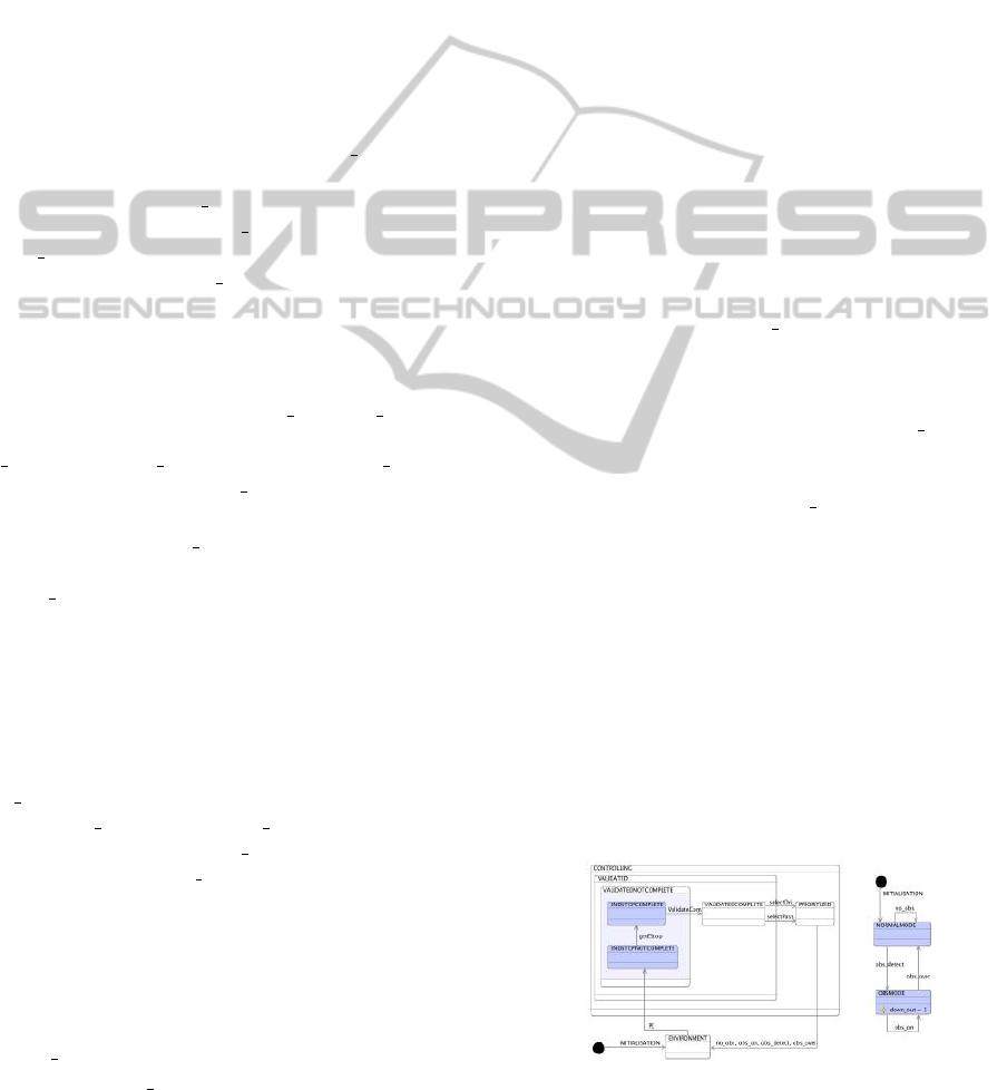
Figure 7 is the UML-B representation of the
RRMD in Figure 6. In the UML-B syntax, control
flow edges become states, and blocks of a RRMD be-
come transitions. For example, block PE becomes
a single transition (state machine of PE has a single
transition). Block SelCommand has two transitions,
so two parallel transitions in the UML-B model: se-
lectDri and selectPass. This kind of encoding is true
when blocks are not state-holding. When a block is
state-holding as in case of Ex comm, we create an or-
thogonal state machine (Figure 7). The state machine
in the left encodes the outer control loop behaviour
of the RRMD in Figure 6(a); the state machine in the
right is same as the block state machine of Ex comm.
In the first state machine (Figure 7), the single transi-
tion between states PRIORITIZED and ENVIRON-
MENT represents the block Ex comm; this single
transition is labelled with all the transition names of
the state machine in the mode state machine (in the
right). During execution, both these state machines
are synchronized on the same transition labels.
Each RRMD corresponds to an Event-B model.
The UML-B tool can make this translation. In a
UML-B model, invariants can be added to the states
of the UML-B state machine. Upon translation, these
invariants are directly lifted to the Event-B model.
Tools like Rodin Platform (Abrial et al., 2010) can be
used to discharge the proof obligations. The UML-B
model and Event-B translation with proofs are avail-
able as a Rodin archive (Snook, 2012).
Figure 7: UML-B representation of the RRMD in Figure 6.
MODELSWARD2013-InternationalConferenceonModel-DrivenEngineeringandSoftwareDevelopment
146

6 RRMD TO SL/SF
In a fully developed RRMD, all blocks excepting the
PE are deterministic; PE gives non-deterministic val-
ues to environmental outputs. We next remove the
control flow edges because at this stage, data flow
edges determine the control flow. Next if we remove
block PE and ignore the block internals, then it looks
like a SL/SF model; i.e., if we view it as a SL/SF
model, the inter-block connections would remain the
same. In other words, if we translate the block inter-
nals to Simulink subsystems, then we would get an
equivalent SL/SF model.
6.1 RRM Block to Simulink Subsystem
If a RRMD block is state-holding, then we make it a
Stateflow subsystem. The structure of Stateflow chart
remains exactly the same as the block state machine.
The guard/action of a transition in the block state ma-
chine becomes the guard/action of the corresponding
transition in the Stateflow chart; however, the State-
flow syntax needs to replace the RRMD syntax. If
a block is not state-holding, we translate this block
state machine to a Simulink subsystem. Based on the
pattern of the state machine, we define the following
mapping functions:
• If the pattern is as in Figure 8(a), then based on
the guards of the transitions, an if-else-if Simulink
block is created. In the figure, guards g1, g2 and
g3 are mutually exclusive (this is by construction),
and they become the conditions in the if-elseif-
else Simulink block; its outputs trigger the sub-
systems for the transition actions, and the outputs
of such subsystems are fed to a merge Simulink
block; refer to the figure. The guards and actions
are translated to the Simulink syntax.
• If the pattern is as in Figure 8(b), the translation
is similar excepting the sequencing of the subsys-
tems corresponding to actions A3 and A4.
• If the pattern is of type as in Figure 9, then the
translation leads to a hierarchy of if-else-if blocks
Figure 8: RRMD blocks to Simulink subsystems-I.
as shown in the same figure.
6.2 SL/SF Translation Tool
The UML-B to SL/SF translator is available as a
toolbar button that is enabled when a UML-B state-
machine is selected in the Rodin editor view. The
state-machine must represent an RRMD top-level di-
agram. The translator tool generates a MATLAB
m-script text file containing commands that build a
SL/SF model. The m-script file can be loaded using
the MATLAB command window. Figure 10 shows
the auto-generated SL/SF model for the PWC-OD,
and Figure 11 shows the Stateflow chart of the sub-
system ExecuteCommand (EX comm in RRMD).
7 ANALYSIS OF OUR METHOD
SL/SF Design Generation. At present, most of the
controllers are developed using SL/SF designs. En-
gineers are very comfortable with SL/SF; many val-
idation frameworks like model-in-loop, processor-in-
loop etc. exist around SL/SF designs. If engineers are
supplied with high quality SL/SF designs, they would
readily accept those; the same cannot be said if code
is directly given to them. Our work provides a way of
introducing formal methods in current industrial prac-
tice, thus it contributes to the formal methods com-
munity. We also contribute to the SL/SF community;
at present models are obtained manually, whereas our
method generates them automatically.
Problems with Manual Generation. Generating
SL/SF designs directly from requirements is a big in-
tellectual step, and the process can be error-prone.
Since we use formal refinements, and invariants are
proved using tool support, we can claim that the
SL/SF designs that we generate are of high quality.
Refinements of RRMDs. We have observed from
five industrial case studies that refinements defined
over RRMDs lead to valid refinements in Event-B.
Formalisation of RRMD refinements is a part of our
future work.
Figure 9: RRMD blocks to Simulink subsystems-II.
SystematicDevelopmentofControlDesignsviaFormalRefinement
147
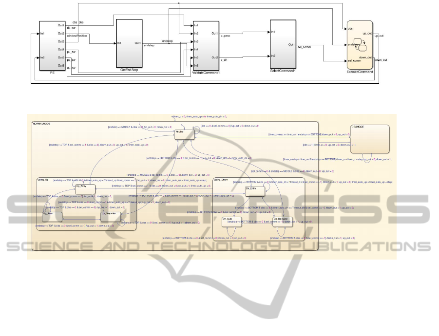
Figure 10: SL/SF design of PWC-OD, auto-generated from its RRMD.
Figure 11: Stateflow chart of the ExecuteCommand subsystem in Figure 10.
8 CONCLUSIONS
We have shown how Event-B models can be gener-
ated in a systematic manner using RRMDs. RRMDs
offer a visual perspective to the whole development
process. Through an automotive case study, we have
shown how RRMDs can deal with requirements in a
systematic manner. Our approach also provides a sys-
tematic way of obtaining SL/SF control designs from
requirements.
REFERENCES
Abrial, J.-R. (2010). Modeling in Event-B - System and
Software Engineering. Cambridge University Press.
Abrial, J.-R., Butler, M. J., Hallerstede, S., Hoang, T.,
Mehta, F., and Voisin, L. (2010). Rodin: An
open toolset for modelling and reasoning in Event-
B. Intl. J. on Software Tools and Technology Transfer,
12(6):447–466.
Leuschel, M. and Butler, M. (2008). ProB: An automated
analysis toolset for the B Method. Intl. J. on Software
Tools for Technology Transfer, 10(2):185–203.
Mathworks (2012). Simulink power window con-
troller specification, http://www.mathworks.co.uk/
help/simulink/examples.
Snook, C. (2012). Power window case study models in
UML-B and Event-B with generated Simulink model,
http://eprints.soton.ac.uk/345699/.
Snook, C. and Butler, M. (2006). UML-B: Formal mod-
eling and design aided by UML. ACM Transactions
on Software Engineering and Methodology (TOSEM),
15(1):92–122.
Snook, C. and Butler, M. (2008). UML-B and Event-B: An
integration of languages and tools. In IASTED Inter-
national Conference on Software Engineering.
MODELSWARD2013-InternationalConferenceonModel-DrivenEngineeringandSoftwareDevelopment
148
