
A PIM-to-Code Requirements Engineering Framework
Gayane Sedrakyan and Monique Snoeck
Management Information Systems, Katholieke Universiteit Leuven, Leuven, Belgium
Keywords: UML, Conceptual Modelling, Executable Model, Modelling Tool, Model Driven Architecture, Model
Simulation, Prototyping, Model Testing, Model Validation, Model-Driven Engineering.
Abstract: The complexity of Model-driven engineering (MDE) leads to a limited adoption in practice. In this paper we
argue that MDE offers "low hanging fruit" if creating executable UML models allowing core functionali-
ty prototyping is targeted rather than developing full-fledged information systems. This paper describes an
environment for designing and validating conceptual business models using the model-driven architecture
(MDA). The deliverable of the proposed modelling environment is an executable platform independent
model (EPIM) that is further tested and validated through an MDA-based simulation feature. The proposed
environment addresses a set of challenges associated with 1. shortcomings of the UML for being technically
too complex for conceptual modelling goals as well as for being imprecise for rapid prototyping; 2. difficul-
ties of MDE adoption due to the large set of required skills to adopt the key MDA standards such as the
UML, MOF and XMI. The paper aims to introduce the current work and identify the needs for future re-
search.
1 INTRODUCTION
Model-driven architecture (MDA) and engineering
(MDE) are new initiatives which have produced a
large amount of research and published material.
Somewhat paradoxically MDE is too little used in
practice, mainly because existing MDE solutions
require extensive training due to the large set of
skills required for using accepted standard MDA
technologies and because MDE solutions often con-
strain themselves to specific architectures, platforms
and 3-rd party technologies, making the reuse of
transformations difficult. In this paper we argue that
MDE offers "low hanging fruit" if creating executa-
ble UML models allowing core functionali-
ty prototyping is targeted rather than developing
full-fledged information systems. This paper de-
scribes an environment for designing and prototyp-
ing conceptual business models using the model-
driven architecture (MDA). Such approach benefits
to the business analyst's model understanding and to
the communication with and validation of models by
business domain experts.
2 PROBLEM DOMAIN
MDE focuses on 1. designing platform independent
models as the main representation of a system-to-be,
having a sufficient level of completeness to generate
other models or code from them; 2. transfor-
mation(s) (mappings) from platform independent to
platform specific models or code, a process that may
pass through a number of mappings before a soft-
ware artefact can be generated. The OMG offers the
MDA as a set of standards to realise this MDE ap-
proach. The key standards include (a.o.) the UML,
Meta-Object Facility (MOF), XML Metadata Inter-
change (XMI) and Object Constraint Language
(OCL). As stated in (Borland, 2004): “The technical
complexity of UML has been held responsible for
modelling adoption issues. Few expert modellers can
rapidly evolve an application from requirements to
code. ... Many of today’s modellers are casual in
their approach; MDA, however, requires increased
rigor and training in UML modelling”. (Erickson
and Siau, 2007) present the complexity metric of the
UML which scores from 2 to 11 times more com-
plex than those of other methods due to the diversity
of supported constructs and diagrams. Among the
other fundamental deficiencies of UML is that it is
unclear how to combine interactive, structural and
163
Sedrakyan G. and Snoeck M..
A PIM-to-Code Requirements Engineering Framework.
DOI: 10.5220/0004344701630169
In Proceedings of the 1st International Conference on Model-Driven Engineering and Software Development (MODELSWARD-2013), pages 163-169
ISBN: 978-989-8565-42-6
Copyright
c
2013 SCITEPRESS (Science and Technology Publications, Lda.)

behavioural aspects together in a single model
(Gustas, 2010). Furthermore, (Buckl et al., 2010)
points out the “noisiness” of modelling languages
with various concepts, that can result in misusing
concepts and creation of unintended models, i.e.
models that use the language concepts in a way not
intended for the modelling domain.
The same holds true for the OMG's MOF and XMI
standards which are used to store, transport and
exchange models between tools. XMI is extensively
used by translationist approaches that start with
PIMs and progressively add refinements to produce
PSMs. The main purpose of XMI is to enable the
interchange of meta data between tools in heteroge-
neous environments. Despite these benefits XMI is
also associated with issues like semantic mismatch-
es, version incompatibilities (XMI/UML/MOF),
human-readability, etc. Finally, transformations are
mostly written using platform specific technologies
and often have extensive dependencies on 3
rd
party
technologies such as application and database serv-
ers, making their (re)use unnecessarily complex for
prototyping purposes.
In theory, the MDA/MDE approach aims to simplify
the development process in order to address the
problems of rapidly changing business requirements
and technologies by making the development pro-
cess less dependent on specific programming lan-
guages and platforms. To achieve this goal MDE
aims at a higher level of abstraction and genericity
by grounding the development process onto models
and allowing model-to-model transformations to
bridge across platforms and languages. Such model-
based abstraction on the other hand, creates its own
share of complexity in practice with existing solu-
tions continuously growing into a large all-in-one-
capable pot. For instance, UML aims at genericity
by supporting modelling various views of a system
but on the other hand fails to provide good means of
separating aspects per development phase (e.g. con-
ceptual modelling versus program design). UML
also fails to provide good support for recombining
different views into one global and consistent model.
Furthermore, although current approaches for mod-
el-to-model transformations attempt to achieve high
traceability among models, this goal has not been
adequately realized yet. Debugging and runtime
performance modifications are still tied to the code
level and cannot easily be traced to the model-to-
code or (even more difficult) to the preceding mod-
el-to-model transformations. Despite the promise of
easing the development process by getting rid of
platform dependence, in current practice, MDE
doesn’t simplify the development process in terms of
traceability and maintainability.
Thus, while MDE seems very promising, its practi-
cal utility is still limited by the fact that:
UML is too complex to achieve a right design
within a short time to be further processed with
an MDE approach
MDE model-to-model and model-to-code trans-
formations are hard to write, debug, maintain and
reuse
Despite these hurdles, we believe that MDE can be
feasible and offer a "quick win" if prototyping is
targeted rather than the development of full-fledged
information systems and if mappings to PSMs are
skipped and PIMs are directly transformed to code.
Restriction to prototyping makes sense because it
allows creating executable PIMs (EPIM). The cur-
rent standard of MDD is the executable UML
(xUML) which provides a key technology for ex-
pressing application domains in a platform inde-
pendent manner. The xUML is a profile of UML 2.0
that defines the execution semantics for a subset of
the UML. The Foundational UML (fUML) and the
Action Language for fUML (Alf) are the new exe-
cutable UML standards: fUML specifies precise
semantics for an executable subset of UML, and Alf
specifies a textual action language with fUML se-
mantics. These however do not bring the MDE any
closer to the novice modellers or simplify it such as
making model validation by means of rapid proto-
typing easily feasible for technical and business
domain experts. Still a very detailed diagramming
with fUML is required and a solid knowledge of
both fUML and Alf is required to make further
transformation of UML to code. We will use the
MERODE methodology and a proposed prototyping
tool which will allow us to filter away unnecessary
detail, use the consistency by construction provided
by its modelling tool to minimize required input
skills (thus tailoring the approach to novice users),
as well as make it possible to receive automated
feedback in the prototypes. In this paper the term
executable PIM refers to a sufficient level of ab-
straction and completeness of the PIM enabling
applying transformation(s) from platform independ-
ent to platform specific models or code. The
straight-to-code approach enables rapid simulation
of a model which 1) improves a modeller under-
standing of the PIM; 2) improves the communication
with business experts leading to decreased require-
ments engineering cycles, benefiting the time-to-
market of the final IS. Additionally the straight-to-
code approach simplifies the development of model-
to-code transformations, their debugging and
MODELSWARD2013-InternationalConferenceonModel-DrivenEngineeringandSoftwareDevelopment
164
maintenance and facilitates their reuse.
Putting MDE at work in this way requires simplifi-
cation techniques to meet these goals. The proposed
simplification within the research presented here
include:
the use of a restricted part of UML as proposed
by the MERODE methodology (Snoeck et al.,
1998)
the use of a template-based transformation ap-
proach going straight from model to code (i.e. a
model-to-text transformation).
Starting from a high-level PIM (close to a Computa-
tional Independent Model (CIM)) allows removing
or hiding details irrelevant for a conceptual model-
ling view. This makes the approach easier to under-
stand and a one-click prototype production lowers
the required skill-set for its useful application. Next,
because of an absence of debugging techniques
across models and platforms, the straight-to-code
transformation is easier to create, reuse and maintain
than a set of intermediate model-to-model incre-
ments. To operationalize this, we developed a re-
quirements engineering environment that includes a
proprietary modelling tool JMermaid and its com-
panion simulation tool that assists in creating enter-
prise models according to the MERODE
methodology. Advantages of a proprietary environ-
ment over the industry tools include: 1) a simplified
modelling tool adapted to conceptual modelling
goals, 2) models that are readily transformable to
code, making them truly executable, 3) a fully func-
tional prototype generated by a “single click”. In the
specific case of JMermaid, the generated prototype
is augmented with a feedback feature that links parts
of the applications to the corresponding part of the
model (Sedrakyan and Snoeck, 2012). Such an
approach yields additional benefits such as better
support of the process of developing modelling
competences and the ability to involve end-users
early on in the development of the system-to-be by
letting them test the incrementally growing proto-
types.
3 CONCEPTUAL MODELLING
WITH JMERMAID TOOL
To address the indicated UML issues MERODE
adapts the use of UML to 1) alleviate the problem of
“noisiness” of UML, and 2) ensure the quality and
"transformability" of the model. In MERODE the
object-oriented business model typically consists of
3 system views that together define a platform inde-
pendent model. The business domain model consists
of a class diagram, an interaction model and a num-
ber of state charts. JMermaid is an adapted model-
ling tool for modelling conceptual business models
based on the MERODE concepts. The 3 system
views in the tool are represented with a tabbed view
which suggests an intuitive, incremental and itera-
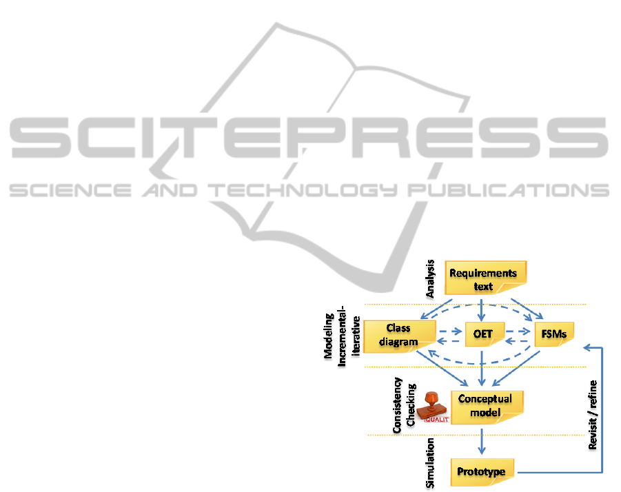
tive modelling process. Figure 1 depicts the artefacts
and modelling cycle with MERODE within the
proposed adapted environment. The class diagram is
a restricted form of UML class diagram: the types of
associations are limited to binary associations, with
a cardinality of 1 to many or 1 to 1. Many to many
associations need to be converted to an intermediate
class. The interaction model consists of an Object-
Event Table (OET), created according to the princi-
ples of MERODE (Snoeck and Dedene, 1998). It
represents a kind of CRUD-matrix, a technique
borrowed from Information Engineering (Martin,
1982). In MERODE, "business events" represent
atomic actions from the real world in which one or
more domain objects can participate. Each business
event is assigned an owner class indicated by an
"O/" preceding the kind of involvement (Create,
Modify, End).
Figure 1: Modelling cycle and artefacts with MERODE.
The other participants are considered as "Associat-
ed" participants and have the C, M or E preceded by
"A/". The finite state machines allow the object type
to impose sequence constraints on the business
events it is involved in. Multiple Finite State Ma-
chines (FSMs) allow to model independent aspects
as parallel machines.
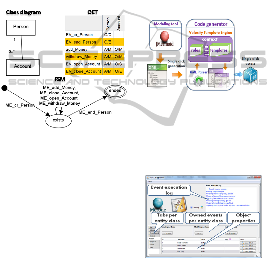
Figure 2 shows a snapshot combining the three main
views supported in the JMermaid modelling tool. To
ensure the completeness of a model to be processed
by a code generator the tool uses consistency check-
APIM-to-CodeRequirementsEngineeringFramework
165
ing and validation techniques. To simplify its usage,
the tool allows managing consistency between the
three views in an automated way: it follows a "con-
sistency-by-construction" approach (Snoeck et al.,
2003); (Haesen and Snoeck, 2004) meaning that
each time when entering specifications in one view,
specifications that can be derived for other views are
automatically generated by the tool. As an example,
one of the design guidelines states that when defin-
ing a class, one should provide at least one method
Figure 2: Modelling views within JMermaid: class dia-
gram, Object-Event Table (OET) and a Finite State Ma-
chine (FSM).
to create instances of that class and one method to
terminate instances. So when a business object is
entered in the class diagram, the necessary comple-
tions are automatically performed in the OET and
FSM views. This modelling approach ensures a
perfect integration between the structural, interac-
tive, and behavioural aspects, achieving models that
are truly executable to be further validated through
the prototyping feature.
4 MDA-BASED EXECUTION
Transformation to code can be achieved through a
single click: the output is a Java project containing
both a compiled application in executable JAR for-
mat and the source-code. The minimal input that can
be accepted by the prototyping tool is actually a
model that contains at least one business object in
the class diagram view along with the minimal set of
default elements, state machine states and transitions
that are automatically generated by JMermaid. A set
of default attributes for business objects, if not speci-
fied by a user, are automatically generated too.
The code generator for MERODE was built us-
ing the Java language and Velocity Templates En-
gine (http://velocity.apache.org). Figure 3 shows the
transformation process behind the prototyping fea-
ture. The generator takes as an input the XML file
(output of the JMermaid modelling tool). The XML
parser module then “collects” the properties (rules)
defined by a model, the code generator module fur-
ther distributes the properties into template contexts.
Figure 3: MERODE prototype generator’s structure.
It is the template engine’s responsibility then to
merge each context with a specified template to
generate a set of files, e.g. a database script, data
access objects, hibernate mappings, event handlers
and user interfaces or configuration files. Finally, the
compiler module transforms the bunch of files into a
compiled executable application. Velocity template
contexts act as mapping contracts between the EPIM
and the prototype code.
Figure 4: The main GUI of the prototype application.
The compiler module uses the IBM’s eclipse com-
piler for Java (ECJ) making it possible to incremen-
tally compile any modification made to the
generated prototype’s code afterwards which can be
MODELSWARD2013-InternationalConferenceonModel-DrivenEngineeringandSoftwareDevelopment
166
made in a simple text editor. A lightweight Hyper-
sonic database is included in the application package
(http://hsqldb.org) with a user interface that can be
invoked from inside a prototype application.
A user interacts with the generated application
through the graphical user interface (GUI) which
offers basic functionality like triggering the creating
and ending of objects, and triggering other business
events. Figure 4 shows the main interface of a gen-
erated prototype. The GUI layer is built on top of the
event handling layer. The event handling layer con-
sists of a collection of so called event handlers. The
task of the latter layer is to handle all events correct-
ly by managing the appropriate interactions with the
objects in the persistence layer.
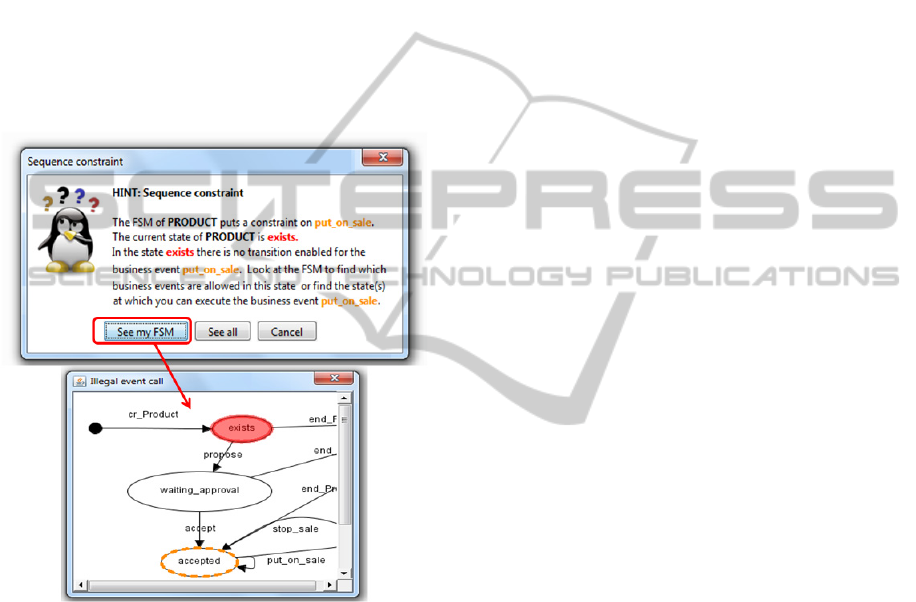
Figure 5: Automated feedback on event execution refusal.
The working of an event handler can be described in
four steps: 1) upon an event execution call the event
handler ‘asks’ every participating object (the partici-
pants to a business event that have been specified in
the Object-Event Table) whether all preconditions
set by the object are met. For example, associations
between classes will lead to preconditions to main-
tain referential integrity; 2) Similarly to the previous
step the event handler retrieves from every partici-
pating object its current state (or reference to the
corresponding state object) and checks whether that
state allows further processing of the event; 3) If all
results of the tasks in step 1 and 2 are positive, the
event handler invokes the methods in the participat-
ing objects, i.e. corresponding event triggered in
response to processing the originally called event in
the specific object; 4) next, if all results of previous
steps are positive, the event handler executes the
method in all participating objects retrieved in step 2
to implement the state modifications (according to
the triggered event).
While executing a business event in a prototype
application users can follow in an event execution
log frame what is happening in the upper right cor-
ner of the generated application. When an event is
refused (because of failed precondition checks) the
user is informed of the refusal with a message that
explains the reason of rejection by indicating what
constraint of a model is violated (e.g. creation/end
dependency or integrity constraint, FSM imposed
constraint, etc.). Figure 5 shows for example how
the triggering of a business event is refused by the
application because the business rules stated in the
form of a Finite State Chart impose a precondition
that is not met by the current state of the business
objects. The automated feedback includes an expla-
nation message followed by graphical visualisation
upon user’s request. Such model execution with
automated feedback enables a much better under-
standing of models than can be obtained by just
reading a model.
5 EXPERIENCES
AND EVALUATION
In its current form, the tool is mainly used in a
teaching environment. Hence, the optimizations
have been mainly motivated by the educational con-
text and are therefore based on our observations of
student achievements over a period of 5 years, ex-
periments and observations of a progress curve of
delivered results from tasks before and after the use
of code generator, constant feedback from 300 stu-
dents overall, as well as similar issues found in re-
lated research. Previously the simulation was
achieved through a chain of several transformation
and execution steps before being able to run the
prototype. The prototyping process was in addition
complicated by an extra dependency of a generated
prototype on an application server. Furthermore, the
graphical visualizations of errors were implemented
as an optional plugin students could extend their
prototypes with. Due to their low technical skills,
students experienced various difficulties throughout
the simulation process chain, which made the major
part of students reluctant in using the feature mostly
resulting in “didn’t use” answer while evaluating the
feature. Despite these early problems the prototyping
APIM-to-CodeRequirementsEngineeringFramework
167

and errors’ visualizations were rated above average
by the students. Furthermore, a little experiment
conducted with students before and after the use of
simulated model resulted in the positive correction
of 1,16 in the interpretation of a model, increasing
from 7,63 to 8,59 in a range of 0-10. In the mean-
time, the problems with the simulation chain have
been solved by providing students with an all-in-one
package allowing to generate and start a prototype
with a single click from the student side as described
in this paper. We therefore expect this tool to score
even better in 2012-2013 resulting in a much higher
positive correction. The preliminary test among 49
novice learners using true/false questions to assess
the understanding of a model (both structural and
behavioural aspect) already confirmed the expecta-
tions: for 6 question out of 9 positive corrections
{21, 1, 4, 2, 6, 8} are observed. However, for 3
questions still some negative impact was observed.
This indicates that for a novice modeller identifying
right scenarios for testing a model can be yet another
issue in using a prototype to validate a model.
Hence, the need to improve testing capabilities or
even providing tool assistance in developing test
scenarios can be considered while implementing
further extensions. This also suggests improvements
in designing the experiments for evaluating the tool
such as clustering of the users according to their
expertise (e.g. novice, intermediate, advanced…).
6 CONCLUSIONS
While the use of existing MDE approaches require
extensive training, the current research demonstrates
how a (template-based) MDE approach can be put at
work to the benefit of conceptual modelling, requir-
ing a minimal input and minimal skill-set of busi-
ness analysts. The proposed environment also claims
that the resulting simulation facilities for EPIMs
improves the business analyst's understanding of a
model, yielding better modelling decisions and eas-
ing the end-users’ involvement in the validation
cycle. In its current form, the tool is used in a teach-
ing environment and already revealing its capability
of increasing the students understanding of models
(Sedrakyan and Snoeck, 2012). The tool can be
further validated by industry users.
Among the possible evolutions of the work could be
to address current limitations of the code generator,
such as the extension with an ability to generate
code from models that use inheritance and support
for general constraints formulated in OCL. The
enhancement with OCL support would allow to
swiftly validate a set of business rules implemented
by means of a conceptual model. Another possibility
for extension is the development of a user-friendly
interface to allow modification of the structure of the
generated application to better tailor it to the user's
familiar environment. Yet another enhancement
would be to modify the generator in a way that each
entity can be generated as a self-contained compo-
nent that can “inject” itself into a generated applica-
tion as well as be easily removed from it.
REFERENCES
Borland, 2004. Keeping your business relevant with Model
Driven Architecture (MDA). Retrieved from
http://www.omg.org/mda/presentations.htm
Erickson, J., Siau, K. 2007, Can UML Be Simplified?
Practitioner Use of UML in Separate Domains. In
Proceedings EMMSAD'07, Trondheim, Norway, 87-96
Gustas, R., 2010. Conceptual Modeling and Integration of
Static and Dynamic Aspects of Service Architectures.
In Proceedings of ONTOSE, 17-32
Buckl, S., Matthes, F., Schweda, C. M., 2010. A Meta-
language for EA Information Modeling - State-of-the-
Art and Requirements Elicitation. In proceedings
EMMSAD 2010, held at CAiSE 2010, volume 50 of
Lecture Notes in Business Information Processing,
169-181, Springer (2010)
Sedrakyan, G., Snoeck, M., 2012. Technology-enhanced
Support for Learning Conceptual Modeling, In pro-
ceedings EMMSAD 2012, held at CAiSE 2012, vol-
ume 113 of Lecture Notes in Business Information
Processing, 435-449, Springer (2012)
Snoeck, M., Dedene, G., 1998. Existence dependency: the
key to semantic integrity between structural and be-
havioural aspects of object types, IEEE Trans. Soft-
ware Eng., 24(4):233-251
Martin, J., 1982. Strategic Data Planning Methods. Pren-
tice-Hall, Inc., Englewood Cliffs, New Jersey.
Snoeck, M., Michiels, C., Dedene, G., 2003. Consistency
by construction: the case of MERODE, in Jeusfeld, M.
A., Pastor, O., (Eds.) Conceptual Modeling for Novel
Application Domains, ER 2003 Workshops ECOMO,
IWCMQ, AOIS, and XSDM, Chicago, IL, USA, Oc-
tober 13, Proceedings, 2003 XVI, 410 p., Lecture
Notes in Computer Science, Volume 2814, pp.105-117
Haesen, R., Snoeck, M., 2004. Implementing Consistency
Management Techniques for Conceptual Modeling,
accepted for UML2004: 7th conference in the UML
series, Lisbon, Portugal, October 10-15, (2004).
MERODE: http://merode.econ.kuleuven.be
JMermaid. http://merode.econ.kuleuven.be/mermaid.aspx
OMG, Model-Driven Architecture.
http://www.omg.org/mda/
Foundational Subset for Executable UML Models
(FUML), Version 1.0.
http://www.omg.org/spec/FUML/1.0/
MODELSWARD2013-InternationalConferenceonModel-DrivenEngineeringandSoftwareDevelopment
168

Alf 1.0 Specification:
http://www.omg.org/spec/ALF/Current
The Apache Velocity Project. http://velocity.apache.org/
Hibernate Object/Relational Mapping Framework.
http://www.hibernate.org/
Eclipse, ECJ compiler for Java. http://www.eclipse.org/.
APIM-to-CodeRequirementsEngineeringFramework
169
