
Novel Wireless Capsule Endoscopy Diagnosis System
with Adaptive Image Capturing Rate
Zhi Jin, Tammam Tillo, Eng Gee Lim, Zhao Wang and Jimin Xiao
Department of Electrical and Electronic Engineering, Xi’an Jiaotong-Liverpool University, Suzhou, China
Keywords:
Wireless Capsule Endoscopy, Smart Image Capturing Rate, Image Recognition Technique.
Abstract:
Wireless Capsule Endoscopy (WCE) is a device used to diagnose the gastrointestinal (GI) track, and it is one
of the most used tools to inspect the small intestine. Inspection by WCE is non-invasive, and consequently it
is more popular if compared to other methods that are traditionally adopted in the examination of GI track.
From the point of view of the physicians, WCE is a favorable approach in increasing both the efficiency and
the accuracy of the diagnosis. The most significant drawback of WCE is the time consumption for a physician
to check all the frames taken in the GI track, in fact it is too long, and could be up to 4 hours. Many anomaly-
based techniques were proposed to help physician shorten the diagnosis time, however, these techniques still
suffer from high false alarm rate, which limits their actual use. Therefore, in this paper we propose a two stage
diagnosis system that firstly uses a normal capsule to capture the whole GI track, and then we use an automatic
detection technique that detects anomalies with high false alarm rate. The low specificity of the first capsule
ensures that no anomalies will be missed in the first stage of the process. The second stage of the proposed
diagnosis system uses a different capsule with adaptive image capturing rate to re-capture the GI tract. In this
stage the capsule will use high image capturing rate for segments of GI tract where an anomaly was detected
in the first stage, whereas, in the other segments of the GI tract a lower image capturing rate will be used in
order to have better use of the second capsule’s battery. Consequently, the second generated video, which will
be inspected by the physician, will have higher resolution sequence around the areas with suspected lesion.
1 INTRODUCTION
The history of endoscope use to inspect internal or-
gans can be traced back to the 19th century, in
1806, when German scientist Philipp Bozzini first in-
vented the endoscope to inspect human bladder and
bowel(Litynski, 1996). Since then, different types
of endoscopy tools are constantly developed and im-
proved, so for example the gastroscopy is used to de-
tect gastric lesions, and colonoscopy for the intesti-
nal lesions. In the past ten years endoscopy-related
technology developed rapidly, and one of the most
promising technology in this field is Wireless Cap-
sule Endoscope (WCE). One of the benefits of WCE
is that it serves inspecting the stomach and small in-
testine for illnesses. Unlike the usage of conventional
endoscopic methods, in the application using WCE,
there is no hose, which enables the patient to main-
tain normal life activities. Moreover, since the cap-
sule endoscope is small enough to be swallowed, it
significantly reduces the pain caused by traditional
endoscope to the patient, even in comparison with en-
doscope with soft pipes. Furthermore, in comparison
with endoscopy, colonoscopyand other traditional en-
doscope, where due to hose length and bending re-
strictions which limits the depth range of inspection
of the human body, the WCE could be used to inspect
the small intestine. Consequently, it becomes one of
the most effective tools to check the whole section
of the 5-7 meters small intestine(Triester et al., 2006),
where it has been approved by the medical profession,
due to its convenience, hygiene, and effectiveness.
The WCE is a capsule shaped device equipped
with small-sized electronic circuitry, which includes
the built-in LED that light the internal of the GI tract,
the imaging system which captures images, a vari-
ety of sensors, battery, the transmitter module and the
antenna and some other supporting components.The
most popular WCE, developed and manufactured by
Given Imaging (Given, ). Other manufacturer, such
as Olympus Pharmaceutical Company produces their
own capsule. This latter produces the M2A-capsule
endoscope (Olympus, ), with a size of 11 × 27mm.
After being swallowed, it continuously works for 7 to
143
Jin Z., Tillo T., Lim E., Wang Z. and Xiao J..
Novel Wireless Capsule Endoscopy Diagnosis System with Adaptive Image Capturing Rate.
DOI: 10.5220/0004346201430147
In Proceedings of the International Conference on Computer Vision Theory and Applications (VISAPP-2013), pages 143-147
ISBN: 978-989-8565-47-1
Copyright
c
2013 SCITEPRESS (Science and Technology Publications, Lda.)

8 hours in the human body. During this period the
WCE camera will take pictures of the digestive sys-
tem at the rate of two frames per second, and even-
tually captures approximately 50, 000 color pictures.
The capsule shell is made of special biological mate-
rials resistant to stomach acid and powerful digestive
enzymes, and it moves , inside the GI tract, thanks to
the gastrointestinal peristalsis.
In general, there are some limiting factors to the
WCE, the first one is the low quality of the obtained
images by the capsules. This limits the effectiveness
of the image processing techniques, and consequently
it may increase the probability of misdiagnosis. The
main constraint for not being able to increase the res-
olution is the limited capacity of the battery. The sec-
ond limiting factor comes from the fact that the move-
ment of the capsule, inside the GI tract, dependentson
the peristalsis, which means that the instant capsule
speed varies due to the different internal structure of
different individuals. Therefore, the current capsule
system, with the existing image processing methods
and image capturing rate cannot ensure high accuracy
of diagnosis. In fact, when the capsule moves fast,
misdiagnosis may exist.
In (Ping et al., 2011) a comparative study between
the capsule endoscope and the double-balloon en-
teroscopy was carried out, the comparison is in terms
of clinical and economic impact of both methods. In
this study it was reported that the success rate of diag-
nosis is only 81.73% when the WCE was only used.
However, it is stated that the accuracy will increase to
90.56% with the help of double balloon endoscopy.
To overcome some of the limitation of current
WCE, intelligent image processing method could be
used to improvethe rate of successful diagnosis.Given
Imaging Ltd, published a patent (Podilchuk, 2007),
in which feature matching is applied on a number
of captured images with the WCE and an existing
database of images. This technique can be summa-
rized as following, the captured images by the WCE
are compared and matched with a database of im-
ages, using processing system that relay on lesions
features in both sets of images. Then it highlight the
images which are consistent with the required fea-
tures. Thereby, the sensitivity of the system to the sus-
pected lesions has been increased, and this helps doc-
tors by shortening the detection time. However, this
method still cannot overcome the weaknesses caused
by the fast moving of the capsule in the areas with
suspected lesions, and the limited number of captured
pictures when the image capturing rate is fixed. Thus,
although this method improves detection, it still has
large possibility of misdetection.
To have more captured images is also an effective
way to improve the detection rate of lesions. How-
ever, the storage and capturing capability of the cap-
sule itself is limited. In fact, how to effectively ad-
just the image-capturing rate without a substantial
increase in the energy consumption of the capsule,
is one important factor that determines capsule effi-
ciency. In the patent (Han et al., 2010), a technique
to adjust the image capturing rate is proposed based
on the observation that the speed of movement of the
capsule, inside the GI tract, is different in different
organs. So firstly, the time required for the capsule to
reach different organs will be estimated. Then, via a
built-in chip, the image capturing rate is adjusted once
it reaches a certain preset time. This method compen-
sates the fast movement of the capsule in some di-
gestive organs, therefore, the possibility of successful
diagnoses of illnesses is increased. However, tuning
the image capturing rate of this method is not based
on suspicious lesion areas. That is to say, the num-
ber of generated images for the lesions and the nor-
mal regions is the same in the same organ. So this
will increase the burden of post-image processing and
screening.
Thus, in general, the existing WCE is still unsatis-
factory, due to many reasons, among them the image
quality, and the image capturing rate which cause high
probability false detection and misdetection. There-
fore, this becomes the major obstacle for doctors to
detect the patient’s condition quickly and effectively.
This paper proposes a new WCE system with adaptive
image capturing rate, based on two capsules inspec-
tion paradigm. Thus the image capturing rate will be
tuned during the second stage of inspection, based on
the outcomes of the inspection with the first capsule.
The first inspection serves to identify the suspected
lesion regions.
2 NEW PROPOSED
METHODOLOGY
The proposed WCE system and detection method
aims to improve the amount of effective information
and increase the temporal resolution of the captured
video in the suspicious tracts of the digestive system.
This objective is achieved by adjusting the image cap-
turing rate of the capsule. Fig.1 shows the flowchart
of the proposed diagnosis system, which aims through
the use of the first capsule to detect any suspected
lesion regions through the use of image recognition
technique, and consequently to appropriately adjust
the capture rate of the second capsule. The details of
main elements of the system as shown in Fig.1 are as
following: D11 is the first swallowed capsule, which
VISAPP2013-InternationalConferenceonComputerVisionTheoryandApplications
144
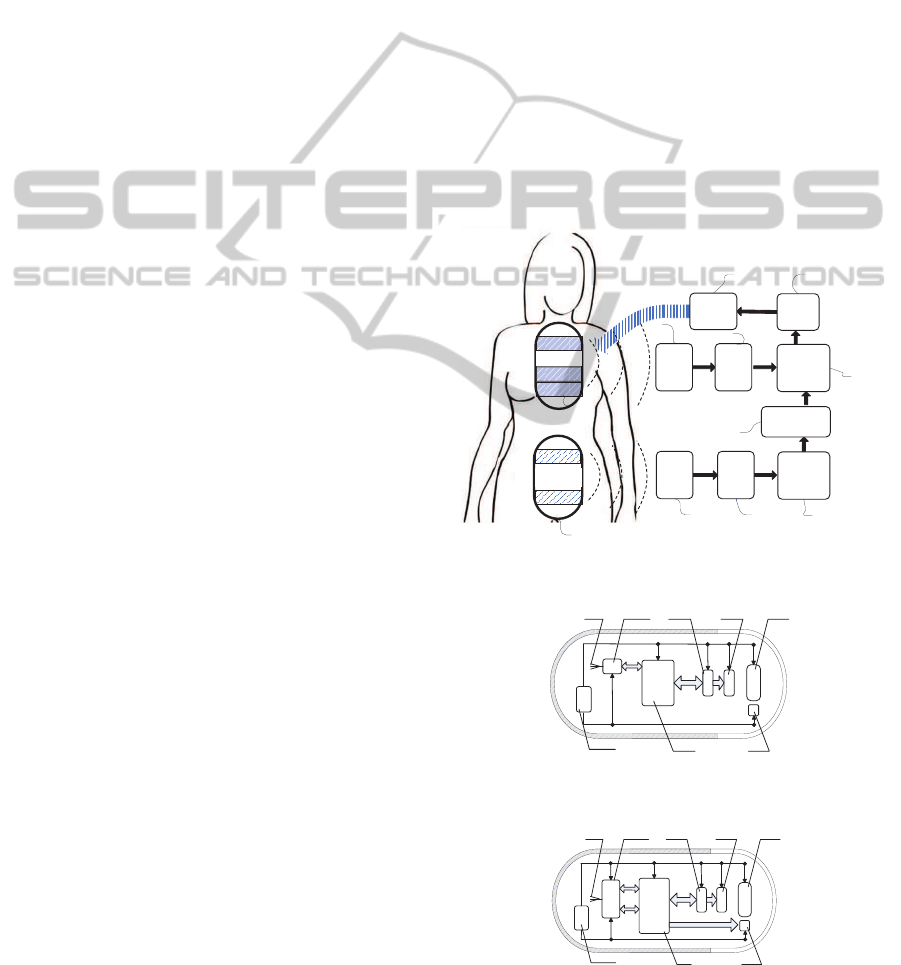
is a traditional capsule with fixed image capturing rate
and it includes a wireless transmitter module, and this
capsule is used during the first diagnosis stage. D12 is
the second swallowed capsule whose capture rate can
be modulated, and it contains a wireless transmitter
and receiver module. This capsule is used for the sec-
ond stage of the diagnosis procedure, and this stage
could start after completing the first diagnosis stage,
or while it is still running. D1 and D2 are the pa-
tient carried built-in receiving apparatus with antenna
arrays, D3 and D4 are the storage units for captured
images, D5 and D6 are image feature identification
devices, D7 is used for storing the captured imaged
after image feature matching with image recognition
system database, D8 is capsule capture rate controller
and D9 is a transmitter.
Shown in the drawing process, the patient needs to
swallow the capsule 1, D11, which can transmit sig-
nal to external body device. The transmission mod-
ule inside can convert the captured images into wire-
less signals and then transmit them across the human
body to the patient carried receiving apparatus D1.
Images stored in the storage unit D3 will be deter-
mined whether has feature consistency with the fea-
ture images of various types of gastrointestinal lesions
by D5. Then these matched images are marked and
the two previous images of the matched image will
also be marked. After swallowing the first capsule,
D11 for a certain period of time, patient can swal-
low capsule 2, D12. Different from the Capsule1, the
Capsule2 can be controlled by receiving external cap-
ture rate changing signal to adjust the capture rate in
different intestinal regions. When D2 receives image
signals captured by the Capsule2, these images will
be identified by the image features device D6 and the
results of comparison with marked images Capsule1.
Once the image captured by capsules 2 is consistent
with the feature image, the rate controller D8 sends
the signal to speed up the capture rate of the capsule.
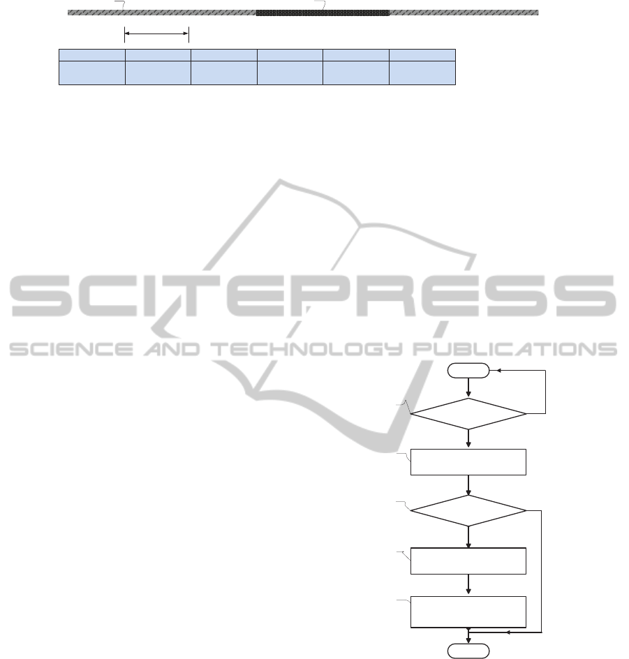
Fig.2 shows a schematic diagram of the existing
design of the capsule; this kind of capsule will be used
in the first stage of the diagnosis. In this figure, 1 point
to the built-in optical system of a capsule, 2 stands for
an image sensor, 3 is the image sensor controller, 4 is
built-in capsule microprocessor, 5 is an illumination
system, 6 is power supply device to provide energy
to the various components of capsule, 7 is a wireless
transmitting device, 8 is an antenna. The built-in mi-
croprocessor controls the wireless receiving module
7 and the image sensor controller 3. Meanwhile, the
image sensor controller 3 controls the image sensor 2.
The wireless transmitter module 7 transmits the sig-
nal to the patient carried receiving device, for further
analysis and processing by the operation processing
system.
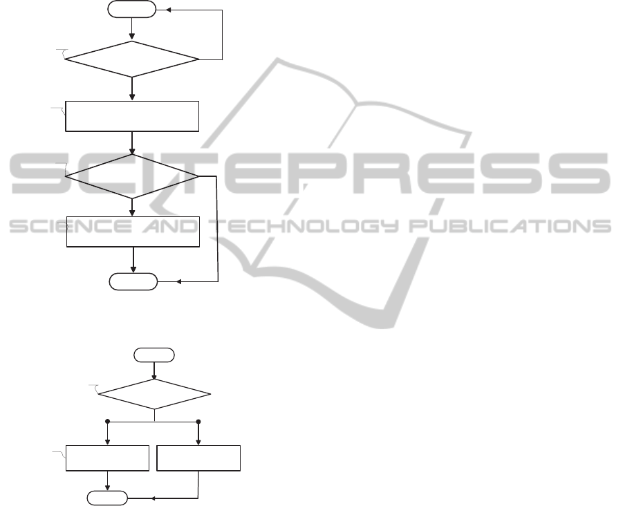
Fig.3 shows a schematic diagram of the Capsule2,
which is used in the second stage of the proposed di-
agnosis process. In this figure, 1 represents the built-
in optical system of the capsule, 2 is the image sen-
sor, 3 is the image sensor controller, 4 is built-in cap-
sule microprocessor, 5 is an illumination system, 6 is
power supply device to provide energy to the various
components of capsule, 7 is a wireless transmitting
device, 8 is an antenna. Different from the Capsule1,
in the Capsule2 the wireless receiver and transmitter
module 7 not only transmits the captured images to
the carried receiver,but also serves to receivean exter-
nal control signal to adjust the image capturing rate,
thereby changing the capsule capture rate in the dif-
ferent tracts of the human digestive system. In Cap-
sule2 the built-in microprocessor controls the wireless
receiving module 7 and the image sensor controller 3,
and the illumination system 5.
Image matching
㜦1
Receiver
Optical
module
Transmitter
㜦2
Optimal
module
Transmitter
Image matching
Receiver
(Capsule 1)
Receiver
(Capsule 2)
Storage
unit
Storage
unit
image
feature
identificatio
n device
image
feature
identificatio
n device
Storage unit
(
suspicious lesion
area images
)
Capture
rate
controller
Transmitter
Time interval
D9
D2
D1 D3
D4
D5
D6
D7
D8
D11
D12
Capsule 2
Capsule 1
Figure 1: The block diagram of the overall system.
1237
6
4 5
8
Figure 2: The main structure of Capsule1.
1237
6
4 5
8
Figure 3: The main structure of Capsule2.
NovelWirelessCapsuleEndoscopyDiagnosisSystemwithAdaptiveImageCapturingRate
145
A B C D E
1
2
No.
Mark
A
Two before the
image
B
One before the
image
C
Lesion region
image
D
Lesion region
image
E
Normal
Figure 4: The adopted method for marking the suspected lesion area in few consecutive frames.
3 IMPLEMENTATION
As shown in Fig.1, the captured images obtained by
the first capsule are transmitted through the human
body to the external receiving apparatus D1, those im-
ages are stored in the storage unit, D3. Then every
photo stored in D3 will be analyzed to detect vari-
ous gastrointestinal lesions by the image processing
system; this system will be tuned so as to have low
specificity, in order to increase the chances of detect-
ing lesions. Moreover, to reduce the probability of
missing any lesions the system will mark few frames
before and after the frame that contains the suspected
lesions and these images will be stored into the stor-
age unit D7. For example, let us suppose that among
the frames f
a
, f
b
, and f
c
, the frame f
c
is suspected
of having some lesions, in this case all the three im-
ages will be stored into storage unit D7. As for the
Capsule2, D12, the patent will swallow it after a pe-
riod of time of swallowing Capsule1. At beginning,
Capsule2 will take pictures by low default speed (this
speed could be set by doctors). Then the transmit-
ted images by Capsule2 will be compared with those
stored in D7. So, when some transmitted images are
positively matched with the feature images in D7, the
image capturing rate controller, D8, will transmit the
signal to wireless capsule endoscope D12 to increase
the capturing rate through transmitter D9. Therefore,
the capsule can take pictures in suspected lesion area
in a faster rate than before. Furthermore, when there
is no more match between transmitted image by Cap-
sule2 and feature image, the capture rate controller
D8 will transmit new signal to change the capture rate
back to the normal low speed in order to save battery’s
energy.
The process of lesion marking is shown in Fig.4.
So, let us suppose that in series of captured images
of digestive tract from frame A to E, there is one le-
sion area in image C and D (region 2: represented as
the dark area). In this case, when the image feature
identification device detects the lesion in picture C
and D, in the video sequence generated by Capsule1,
the picture A, B, C and D will all be marked. All
marked images will be stored in a special database of
image feature recognition apparatus, and when using
the second capsule, i.e., Capsule2, all the new cap-
tured images will be compared with marked images
database directly. At this point if some captured im-
ages by the second capsule match the marked images
of the first capsule, then a signal is transmitted to in-
crease the Capsule2 image capturing rate around the
areas with suspected lesions. This will ensure that
higher quality images will be generated around those
areas, for latter analysis by the physician. When the
built-in reception module in Capsule2 receives a rate
control signal P25, as shown in Fig.7, the capsule will
increase the imaging rate, otherwise it will keep the
normal image capturing rate.
Using the image feature
matching apparatus
Start
Yes
No
Matched with lesion
characteristics images
Receive the data
Yes
Marking the captured images
No
Store the two images before the
matched images into image
feature matching apparatus
End
P11
P12
P13
P14
P15
Figure 5: The flow chart of the working principle of the first
capsule.
The flow chart reported in Fig.5 shows the work-
ing principle of the first capsule. When the data is
received, the image feature matching apparatus will
be used to match the captured image, by the capsule,
with the lesion characteristics images P12. In this
matching process, each captured image will be ana-
lyzed to see whether it matches the stored feature im-
ages in P13. If a match is found these images will
be marked, P14, and stored into another database of
image feature, P15. In Fig.6, the flow chart of the
VISAPP2013-InternationalConferenceonComputerVisionTheoryandApplications
146
working principle of the second capsule is reported.
This has similar working paradigm with the first cap-
sule, except for the image capturing speed, which is
tuned by D8 (in Fig.1). This latter unit will transmit
a signal to the second capsule to increase the image
capturing rate when a match is found with the stored
feature images P13.
No
Yes
Start
Receive the data
Using the image feature
matching apparatus
Received captured image
matched with two images
before the marked image
Yes
Transmit the capture rate
control signal
No
End
P21
P22
P23
P24
Figure 6: The flow chart of the working principle of the
second capsule.
ᱟ
NoYes
Start
Receive the capture rate
control signal
Increase capture rate
End
P25
P26
Normal capture rate
Figure 7: The control mechanism of the image capturing
rate in Capsule2.
4 CONCLUSIONS
This paper proposes a new wireless capsule endo-
scope system, which comprises two diagnosis stages.
The first one uses a normal capsule to capture the
whole GI track. The generated video sequence will
be analyzed to detect anomalies with high false alarm
rate. The second stage of the proposed diagnosis sys-
tem uses a different capsule with adaptive image cap-
turing rate to re-capture the GI tract. In this stage the
capsule will use high image capturing rate for seg-
ments of GI tract where an anomaly was detected in
the first stage, whereas, in the other segments of the
GI tract a lower image capturing rate will be used
in order to have better use of the second capsule’s
battery. Consequently, the second generated video,
which will be inspected by the physician, will have
higher resolution sequence around the areas with sus-
pected lesion. Therefore, this new type of wireless
capsule endoscope system and method will be more
efficient for clinical applications.
ACKNOWLEDGEMENTS
This work is partially supported by the Natu-
ral Science Foundation of Jiangsu province (No.
BK2010251 and BK2011352), Suzhou Science
and Technology Bureau (No.SYG201011 and
SYG201211), and XJTLU Research Development
Fund (No.10-03-16.).
REFERENCES
Given, I. http://www.givenimaging.com.
Han, Z.and Binghe, J., Yongyou, L., and Tie, C. (2010). Im-
age capture rate controllable capsule endoscope. State
Intellectual Property Office of the P.R.C. Native Lan-
guage Patents (SIPO).
Litynski, G. S. (1996). Highlights in the History of
Laparoscopy: The Development of Laparoscopic
Techniques– a Cumulative Effort of Internists, Gyne-
cologists, and Surgeons. Barbara Bernert Verlag.
Olympus. http://www.olympus-global.com/en/global.
Ping, W., Hong, F., Qiang, G., and et al (2011). Clinical
and health economic evaluation of the capsule endo-
scope (ce) or/and double-balloon enteroscopy (dbe) in
diagnosis of intestine disease. China Journal of En-
doscopy, 17.
Podilchuk, C. (2007). Method and system for image recog-
nition using a similarity inverse matrix. United States
Patent application publication (US 2008/0133521
A1).
Triester, S. L. J., G., L., Gurudu, S., and et al (2006). meta-
analysis of the yield of capsule endoscopy compared
to other diagnostic modalities in patients with non-
stricturing small bowel crohns disease. Am J Gas-
troenterol, 101:954–964.
NovelWirelessCapsuleEndoscopyDiagnosisSystemwithAdaptiveImageCapturingRate
147
