
Do we Really Need to Write Documentation for a System?
CASE Tool Add-ons: Generator+Editor for a Precise Documentation
Maria Spichkova
1
, Xiuna Zhu
1
and Dongyue Mou
2
1
Institut f
¨
ur Informatik, Technische Universit
¨
at M
¨
unchen, Boltzmannstr. 3, 85748 Garching bei M
¨
unchen, Germany
2
Fortiss GmbH, Guerickestr. 25, 81735 M
¨
unchen, Germany
Keywords:
CASE Tools, System Development, Methodology, Formal Model.
Abstract:
One of the common problems of system development projects is that the system documentation is often out-
dated and does not describe the latest version of the system. The situation is even more complicated if we are
speaking not about a natural language description of the system, but about its formal specification. In this pa-
per we discuss how the problem could be solved by updating the documentation automatically, by generating
a new formal specification from the model if the model is frequently changed.
1 INTRODUCTION
System documentation is claimed to be an important
part of the development process but is very often con-
sidered by industry as a secondary appendage to the
main part of the development – modeling and imple-
mentation. The implementation of the system is what
we would like to get at the end, a model of the sys-
tem is what helps us to simulate and to implement
the system, but the documentation is mostly important
“only” for the cooperation of experts of different dis-
ciplines, for maintenance, and for reuse of the system.
This causes the situation that the system documenta-
tion is often outdated and does not describe the lat-
est version of the system: system requirements doc-
uments and the general systems description are not
updated according to the system’s or model’s mod-
ifications – sometimes because this update is over-
looked, sometimes on purpose, because of timing or
costs constraints on the project.
This problem is even more complicated if we are
speaking not about a natural language description of
the system, but about its formal specification. On the
one hand, a formal specification provides a system de-
scription that is much more precise than the natural
language one and it can help to solve a lot of specifica-
tion/documentation problems, but on the other hand,
it takes much more time to write a formal specifi-
cation than an informal natural language description.
Unfortunately, we should acknowledge that dealing
with formal methods often assumes that only two fac-
tors must be satisfied: the method must be sound and
give such a representation, which is short and beauti-
ful from the mathematical point of view, without tak-
ing into account any question of readability, usabil-
ity, or tool support. This leads to the fact that formal
methods are treated by most engineers as “something
that is theoretically important but practically too hard
to understand and to use”, where even small changes
of a formal method can make it more understandable
and usable for an average engineer. Our approach Hu-
man Factors of Formal Methods, HF
2
M (Spichkova,
2012b) focuses on human factors in formal methods
used within the specification phase of a system devel-
opment process (Feilkas et al., 2011; Feilkas et al.,
2009): during requirements specification and during
the development of a system architecture.
However, even a readable formal specification is
hard to keep up to date if the system model is fre-
quently changing during the modeling phase of the
development. This problem could be solved by ap-
propriate automatization: if we make these updates
automatically or generate new (updated) formal spec-
ifications from the model. To allow a simple and intu-
itional design of distributed systems and applications,
Computer-Aided Software Engineering (CASE) tools
are widely used. The CASE tools could also help
to solve the problem with the system documentation:
in this paper we present an extension of the AutoFo-
cus CASE Tool by add-ons that allow to generate the
formal specification according to the ideas presented
in (Spichkova, 2012b) as well as to edit a generated
formal specification or write a specification using the
predefined templates.
170
Spichkova M., Zhu X. and Mou D..
Do we Really Need to Write Documentation for a System? - CASE Tool Add-ons: Generator+Editor for a Precise Documentation.
DOI: 10.5220/0004347101700174
In Proceedings of the 1st International Conference on Model-Driven Engineering and Software Development (MODELSWARD-2013), pages 170-174
ISBN: 978-989-8565-42-6
Copyright
c
2013 SCITEPRESS (Science and Technology Publications, Lda.)

2 CASE TOOL MODEL:
AUTOFOCUS
AUTOFOCUS 3 (H
¨
olzl and Feilkas, 2010; Sch
¨
atz and
Huber, 1999; Sch
¨
atz, 2004) is a scientific CASE tool
prototype
1
implemented on top of the Eclipse
2
plat-
form, and based on a graphical notation and a re-
stricted version of the formal semantics of the FOCUS
specification and modeling language, presented in
Section 3, in particular the time-synchronous frame.
The system structure specification captures in
AUTOFOCUS 3 the static aspects of the system de-
scription: a network of communicating components
working in parallel. Each component has a syntac-
tic interface described by a set of ports, and the net-
work of components is formed by connecting ports
with channels. Each port is either an input or an out-
put port, has a data type and an initial value. Fur-
thermore, each component is declared to be weakly
causal or strongly causal: weak causality models in-
stantaneous reaction, while strong causality models a
reaction with some delay.
System structure specifications in AUTOFOCUS 3
may be separated into hierarchic views in order to
deal with larger models. Components can be refined
into a set of sub-components introducing both local
communication and communication to the environ-
ment through the interface of the parent component.
Atomic components have their behavior specified us-
ing one of the following variants: a stateful automaton
specification or a stateless function specification.
Specifying a system in AUTOFOCUS 3, we obtain
an executable model, which can be validated using
the AUTOFOCUS 3 simulator to get a first impres-
sion of the system under development and possibly
find implementation errors that we introduced during
the manual transformation of the requirements into a
AUTOFOCUS 3 model. Automatisation of this trans-
formation is a future work.
3 FORMAL SPECIFICATION:
FOCUS
The formal background on FOCUS
3
and its exten-
sions are presented in (Broy and Stølen, 2001) and
(Spichkova, 2007). Here we use an optimized ver-
sion of FOCUS developed according to the HF
2
M ap-
proach presented in (Spichkova, 2012b): it allows us
1
http://af3.fortiss.org
2
http://www.eclipse.org
3
http://focus.in.tum.de
to have shorter and more readable formal specifica-
tions. In many cases even not very complicated opti-
mization changes of a specification method can make
it more understandable and usable. Such a simple
kind of optimization is often overlooked just because
of its obviousness, and it would be wrong to ignore
the possibility to optimize the language without much
effort. For example, simply adding an enumeration
to the formulas in a large formal specification makes
its validation on the level of specification and discus-
sion with co-operating experts much easier. The first
results of visual optimization of Focus specifications
are presented in (Spichkova, 2011).
A specification scheme of FOCUS is inspired by
specification approaches like Z (see (Spivey, 1988)),
but the FOCUS framework is much more powerful and
expressive: it supports a variety of specification styles
which describe system components by logical formu-
las or by diagrams and tables representing logical for-
mulas. FOCUS has an integrated notion of time and
modeling techniques for unbounded networks, pro-
vides a number of specification techniques for dis-
tributed systems and concepts of refinement. For ex-
ample, the B-method (Abrial, 1996) is used in many
publications on fault-tolerant systems, but it has nei-
ther graphical representations nor integrated notion of
time. Moreover, the B-method also is slightly more
low-level and more focused on the refinement to code
rather than formal specification. Formal specifica-
tions of real-life systems can become very large and
complex, and are as a result hard to read and to un-
derstand. Therefore, it is too complicated to start
the specification process in some low-level frame-
work, First-Order or Higher-Order Logic directly: the
graphical specification style is essential here.
The central concept in FOCUS is a stream repre-
senting a communication history of a directed channel
between components. A system in FOCUS is repre-
sented by its components that are connected by chan-
nels, and are described in terms of its input/output be-
havior. Thus, the components can interact and also
work independently of each other. The channels in
this specification framework are asynchronous com-
munication links without delays. They are directed
and generally assumed to be reliable, and order pre-
serving. Via these channels components exchange in-
formation in terms of messages of specified types.
A specification can be elementary or composite –
composite specifications are built hierarchically from
the elementary ones. Any specification characterizes
the relation between the communication histories for
the external input and output channels: the formal
meaning of a specification is exactly the input/output
relation.
DoweReallyNeedtoWriteDocumentationforaSystem?-CASEToolAdd-ons:Generator+EditorforaPrecise
Documentation
171
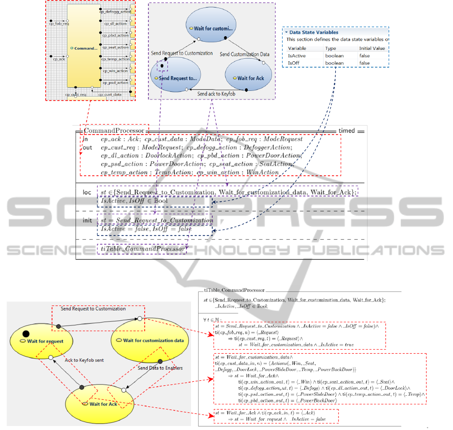
Figure 1: Generation of the component specification.
Figure 2: Generation of the FOCUS timed state diagram (plain text) specification.
4 DOCUMENTATION ARTIFACTS
The FOCUS generator produces a specification of
the model by representing the formal specification in
LaTeX according to the predefined templates. We
choose for the specification generation the most gen-
eral style of a FOCUS specification, that is, an As-
sumption/Guarantee style: where a component is
specified in terms of an assumption and a guarantee:
whenever input from the environment behaves in ac-
cordance with the assumption asm, the specified com-
ponent is required to fulfill the guarantee gar.
For illustration, Figure 1 shows how a formal
specification of an elementary component is gener-
ated from the model:
• The interface part of the FOCUS specification is
generated from the external syntactic interface of
the AutoFocus component (red dotted block).
• The init-part of the specification contains all the
information about the initial values of all the lo-
cal variables for the component state and data.
The initial state is marked in the model by the
black dot – name of this state provides the initial
value of the st varible, where the initial values of
the data state variables are represented separately
MODELSWARD2013-InternationalConferenceonModel-DrivenEngineeringandSoftwareDevelopment
172
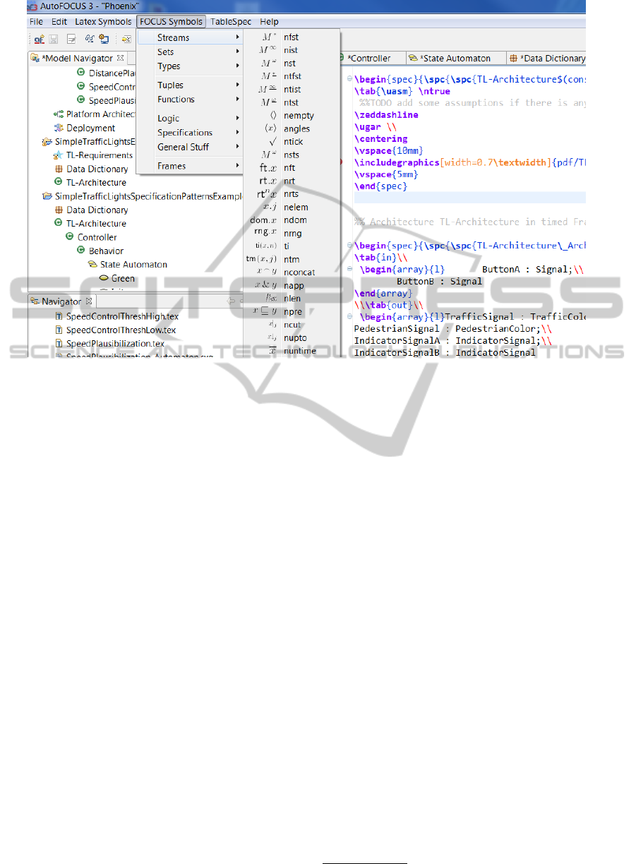
Figure 3: FOCUS editor: Part of a specification template.
(blue dotted block).
• The main part of the specification is generated
from the AutoFocus State Transition Diagram
(lila dotted block). Firstly, the set of component
states builds the corresponding data type of the
state variable st; Secondly, the state automaton
corresponds to the guarantee-part of the specifica-
tion and can be represented by the FOCUS timed
state diagram (represented by a FOCUS automaton
as well as by a plain text specification as shown on
Figure 2) or by a timed table (see also (Spichkova,
2012a)). Each transition of the automaton is de-
scribed by a formula (plain text variant) or by a
line of the timed table.
The FOCUS specification of a composite component
can be represented in two ways:
• graphically, almost similar to the AutoFocus rep-
resentation, or
• by plain text: the guarantee-part of the specifica-
tion describes (i) which local channels the com-
posite component has and (ii) how the subcom-
ponents are connected via these channels.
The generated specification (.tex files) can also be op-
timized or extended manually, using the FOCUS editor
we have implemented and consequently transformed
to the PDF- or DVI-document. Figure 3 shows a
part of a specification template. This editor inher-
its most of the functions from the open source plugin
TeXlipse
4
(e.g., the syntax check of the specification
as well as syntax highlighting, code folding, etc.), and
is extended by additional features such as
• FOCUS operators as well as the main FOCUS
frames: component and function specification,
• FOCUS timed tables,
• predefined data types and streams,
• tool box for the predefined FOCUS operators,
which allows a quick access to the most important
features of the formal language.
Thus, this add-on provides a user-friendly interface
which, on the one hand, is oriented on the features of
the FOCUS language, and on the other hand, does not
require any special sophisticated knowledge.
Both add-ons, the formal specification generator
and the editor, are planed to be a part of the general
distibution of AUTOFOCUS 3.
5 CONCLUSIONS AND FUTURE
WORK
In this paper we introduce a user-friendly tool sup-
port for a formal system documentation. Firstly, we
discuss how the problem with outdated system docu-
mentation could be solved by making the documenta-
4
http://texlipse.sourceforge.net
DoweReallyNeedtoWriteDocumentationforaSystem?-CASEToolAdd-ons:Generator+EditorforaPrecise
Documentation
173

tion updates automatically, by generating a new for-
mal specification from the model if the model is fre-
quently changed. After that an extension of the Auto-
Focus CASE Tool is presented: the add-ons that allow
• to generate a formal FOCUS specification by tak-
ing into account the theories of human factors,
• to edit a generated formal specification, and
• write a specification using the predefined tem-
plates.
The presented results can be integrated into the de-
velopment methodology for verified software sys-
tems (Spichkova et al., 2012; Thyssen et al., 2010).
Using this approach, one can go further and verify
properties of a system in a formal way according
to the methodology “FOCUS on Isabelle”(Spichkova,
2007), by translating the FOCUS specifications to the
semiautomatic theorem prover Isabelle/HOL (Nip-
kow et al., 2002), an interactive semi-automatic the-
orem prover, and using the Isabelle tool to make the
proofs. Using an AutoFocus model one can also take
an advantage of the user-friendly verification environ-
ment for model cheking (Campetelli et al., 2011).
REFERENCES
Abrial, J.-R. (1996). The B-book: assigning programs to
meanings. Camb.Univ.Press.
Broy, M. and Stølen, K. (2001). Specification and Develop-
ment of Interactive Systems: Focus on Streams, Inter-
faces, and Refinement. Springer.
Campetelli, A., H
¨
olzl, F., and Neubeck, P. (2011). User-
friendly model checking integration in model-based
development. In The Twenty-Fourth International
Conference on Computer Applications in Industry and
Engineering (CAINE 2011), Honolulu, Hawaii, USA.
The International Society for Computers and Their
Applications.
Feilkas, M., Fleischmann, A., H
¨
olzl, F., Pfaller, C.,
Rittmann, S., Scheidemann, K., Spichkova, M., and
Trachtenherz, D. (2009). A Top-Down Methodology
for the Development of Automotive Software. Tech-
nical Report TUM-I0902, TU M
¨
unchen.
Feilkas, M., H
¨
olzl, F., Pfaller, C., Rittmann, S., Sch
¨
atz, B.,
Schwitzer, W., Sitou, W., Spichkova, M., and Tracht-
enherz, D. (2011). A Refined Top-Down Method-
ology for the Development of Automotive Software
Systems - The KeylessEntry-System Case Study.
Technical Report TUM-I1103, TU M
¨
unchen.
H
¨
olzl, F. and Feilkas, M. (2010). Autofocus 3: a scien-
tific tool prototype for model-based development of
component-based, reactive, distributed systems. In
Proceedings of the 2007 International Dagstuhl con-
ference on Model-based engineering of embedded
real-time systems, MBEERTS’10, pages 317–322.
Nipkow, T., Paulson, L. C., and Wenzel, M. (2002). Is-
abelle/HOL – A Proof Assistant for Higher-Order
Logic, volume 2283 of LNCS. Springer.
Sch
¨
atz, B. (2004). Mastering the Complexity of Reactive
Systems: the AUTOFOCUS Approach. In Kordon, F.
and Lemoine, M., editors, Formal Methods for Em-
bedded Distributed Systems: How to Master the Com-
plexity, pages 215–258. Kluwer Academic Publishers.
Sch
¨
atz, B. and Huber, F. (1999). Integrating Formal De-
scription Techniques. In Wing, J. M., Woodcock, J.,
and Davies, J., editors, FM’99, volume 1709 of LNCS,
pages 1206–1225. Springer.
Spichkova, M. (2007). Specification and Seamless Verifi-
cation of Embedded Real-Time Systems: FOCUS on
Isabelle. PhD thesis, TU M
¨
unchen.
Spichkova, M. (2011). Focus on processes. Tech. Report
TUM-I1115, TU M
¨
unchen.
Spichkova, M. (2012a). Focus on Time. In In Proceedings
of the 12th International Workshop on Automated Ver-
ification of Critical Systems (AVoCS 2012).
Spichkova, M. (2012b). Human Factors of Formal Methods.
In In IADIS Interfaces and Human Computer Interac-
tion 2012 (IHCI 2012).
Spichkova, M., H
¨
olzl, F., and Trachtenherz, D. (2012). Ver-
ified System Development with the AutoFocus Tool
Chain. In 2nd Workshop on Formal Methods in the
Development of Software, WS-FMDS.
Spivey, M. (1988). Understanding Z – A Specification Lan-
guage and Its Formal Semantics. Cambridge Tracts in
Theoretical Computer Science 3. Camb. Univ. Press.
Thyssen, J., Ratiu, D., Schwitzer, W., Harhurin, A., Feilkas,
M., and Thaden, E. (2010). A System for Seamless
Abstraction Layers for Model-based Development of
Embedded Software. In Software Engineering, SE’10.
MODELSWARD2013-InternationalConferenceonModel-DrivenEngineeringandSoftwareDevelopment
174
