
Model-based Control Approaches for Optimal Integration of a Hybrid
Wind-diesel Power System in a Microgrid
Luis Ismael Minchala Avila
1,2
, Adriana Vargas Mart
´
ınez
2
, Youmin Zhang
2
,
Luis Eduardo Garza Casta
˜
n
´
on
1
, Eduardo Robinson Calle Ortiz
3
and Julio C
´
esar Viola
3
1
Department of Mechatronics and Automation, Tec. de Monterrey, Eugenio Garza Sada 2501, Monterrey NL, Mexico
2
Department of Mechanical and Industrial Engineering, Concordia University, 1455 de Maisonneuve, Montreal, Canada
3
Engineering Research Center for Innovation and Development, Universidad Polit
´
ecnica Salesiana,
Calle Vieja 12-30, Cuenca, Ecuador
Keywords:
Distributed Generation, Hybrid Wind-diesel, Microgrids, Model Predictive Control, Model Reference
Adaptive Control.
Abstract:
This paper presents two model-based approaches for designing control strategies in order to integrate a diesel
generator as frequency and voltage leader in an islanded microgrid configuration. The selected microgrid
configuration is composed of a hybrid wind-diesel system with a battery storage system (BSS). A model
predictive control (MPC) scheme and a model reference adaptive control (MRAC) scheme are selected for
this task, due to its flexibility and capability for handling constraints and fault-tolerance, respectively, which is
helpful for smart grid (SG) architectures to achieve reduced fuel consumption and with and enhanced reliability
and integration of renewable energy sources (RES) into the electrical network. A constrained fuel consumption
strategy has been implemented in the diesel engine generator (DEG) controller with the help of MPC strategy
and fault-tolerance is achieved with MRAC. Different operating conditions of the microgrid were simulated: 1)
diesel-only generation, 2) wind turbine generator (WTG) ignition, 3) sudden connection of 0.5 MW load, and
4) a 3-phase fault with duration of 0.5 seconds. Improved performance over a baseline controller, IEEE type 1
automatic voltage regulator (AVR), is achieved. Dynamic models of the network components are presented in
details on design and implementation of the microgrid configuration in Matlab/Simulink
R
.
1 INTRODUCTION
Microgrids are small-scale low voltage power sys-
tems with distributed energy resources (DER), sto-
rage devices and controllable loads, connected to the
main power network or islanded. Microgrids are
concerned with power generation near the consumers
(Jiang et al., 2009; Gentile, 2009). Nevertheless, mi-
crogrids have different operating characteristics than
bulk power systems (BPS) such as lack of inertia, re-
sistive lines and high penetration of RES.
Microgeneration units, typically located at users
locations, have emerged as an option to meet grow-
ing customer needs for electric power with an em-
phasis on reliability, power quality, and contribution
to different economic, environmental and technical
benefits. The impact on power balance and grid fre-
quency of microgeneration at low voltage levels, such
as wind energy or photovoltaic (PV), is a great cha-
llenge (Schwaegerl et al., 2009). Wind is a promis-
ing RES due to its cleanness and social impact moti-
vated by environmental and economical issues. How-
ever, wind energy also has some limiting characteris-
tics such as: unschedulable, uncontrollable, etc. To
obtain relatively constant power, variable blade pitch
angle controls are installed in the wind turbines (WT)
(Abdin and Xu, 2000; Abdal et al., 2010).
There is a variety of contributions on the field
of simulating and controlling a hybrid wind-diesel
power system. In (Vechiu et al., 2004; Kini and Yara-
gatti, 2006) detailed models of the system compo-
nents of the hybrid configuration are presented, as
well as performance analysis under different operat-
ing conditions, i.e. different wind velocities, load
changes, etc., where IEEE type 1 AVR has been
used. A fully distributed control strategy for a mi-
crogrid configuration integrating a WTG through DC-
link voltage control is studied in (Vandoorn et al.,
12
Minchala Avila L., Vargas Martínez A., Zhang Y., Eduardo Garza Castañón L., Robinson Calle Ortiz E. and César Viola J..
Model-based Control Approaches for Optimal Integration of a Hybrid Wind-diesel Power System in a Microgrid.
DOI: 10.5220/0004359400120021
In Proceedings of the 2nd International Conference on Smart Grids and Green IT Systems (SMARTGREENS-2013), pages 12-21
ISBN: 978-989-8565-55-6
Copyright
c
2013 SCITEPRESS (Science and Technology Publications, Lda.)
2011), where two loops control strategy (voltage and
power) is designed and simulated for the WTG. In
(Kassem and Ali, 2011) a robust control approach for
long term operation of a hybrid wind-diesel system
is presented, a linearized model of the entire system
is proposed through the combination of the subsys-
tem models, and it is used for the design of a central-
ized controller. A MPC strategy has been used for a
stand-alone wind energy conversion system (WECS)
in (Kassem, 2012) and a novel functional MPC is pro-
posed for a faster processing time.
Frequency and voltage regulation in interco-
nnected electrical systems with multiple sources ge-
neration are main control challenges in distributed
generation systems. Many different approaches have
been studied and proposed for both grid-connected
and islanded microgrid operation. Grid-connected
operation relies on main grid parameters and the ma-
jority of contributions are related with volt-var strate-
gies through the use of capacitor banks and flexible
AC transmission system (FACTS), although advanced
control strategies like adaptive controllers for volt-
age regulation at the generation unit are detailed in
(Fusco and Russo, 2008; Fusco and Russo, 2012).
Islanded microgrid operation, on the other hand has
generated the necessity of a frequency leader, or mul-
tiple frequency leaders under faulty scenarios, due to
the high integration of RES whose intermittent cha-
racteristic complicates the use of traditional control
schemes. Voltage and frequency regulation for iso-
lated generators are studied in some research papers;
in (Munoz-Aguilar et al., 2011) a sliding mode con-
trol for voltage amplitude regulation of a stand-alone
synchronous generator connected to a resistive load is
presented, while in (Kumar et al., 2008) a frequency
regulator for a microgrid conformed by a diesel gen-
erator, a wind turbine power, an aqua electrolyzer
and a fuel cell through multiple PI controllers is pro-
posed. A multiagent-based automatic generation con-
trol (AGC) for isolated power systems with dispersed
power sources such as PV, WTG, diesel generator and
energy capacitor systems (ECS) for the energy stor-
age is very well detailed in (Hiyama, 2011).
This paper presents the design methodology for
controlling a hybrid wind-diesel system in islanded
microgrid configuration using two model-based con-
trol approaches: MPC and MRAC. MPC is used for
optimizing RES utilization and minimizing fuel con-
sumption of the DEG with the help of MPC’s opti-
mized performance with constraints handling capabil-
ities. MRAC is used for controlling the system un-
der faulty scenarios due to its capability of adapting
the control output for guaranteeing asymptotic out-
put tracking. The control design objectives are to
maintain desired voltage and frequency (frequency &
voltage leader), and supply energy for the balanced
load (total load - WTG power). With the model de-
veloped for each network component, a distributed
control strategy is then proposed. Different operating
conditions of the microgrid were simulated: 1) diesel-
only generation, 2) wind turbine generator (WTG) ig-
nition, 3) sudden connection of 0.5 MW load, and 4) a
3-phase fault with duration of 0.5 seconds. Improved
performance over a baseline controller, IEEE type 1
AVR, is achieved.
The paper is organized as follows: Section II
presents model generation of the microgrid compo-
nents. Section III deals with the controllers design.
Section IV presents simulation results and perfor-
mance analysis and finally conclusions are drawn in
Section V.
2 MODELING OF MICROGRID
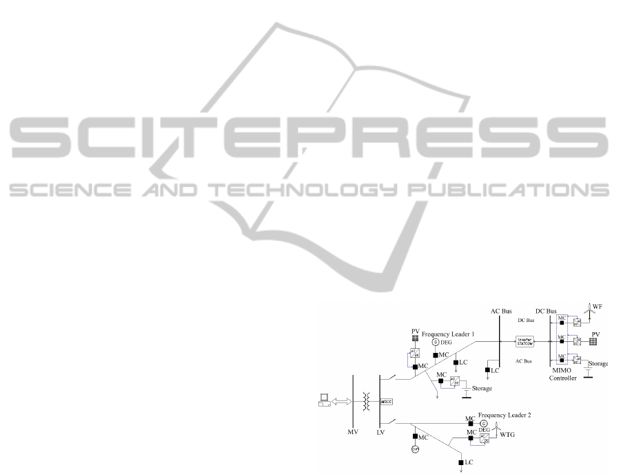
A typical microgrid configuration, consists of DG
units, controllable loads and storage. Fig. 1 presents a
typical microgrid architecture, where it is remarkable
the high penetration of RES and DC-links for inte-
grating these intermitent units into the main grid. In
the following subsections, detailed models of the net-
work componentes are presented.
Figure 1: A typical microgrid architecture.
2.1 Diesel Engine Generator
The DEG is composed of two machines: diesel en-
gine (prime mover) and synchronous generator. In
the following two subsections the diesel engine and
synchronous generator models are presented.
2.1.1 Diesel Engine
For a complete dynamic simulation of the diesel en-
gine, a high order model would be required. How-
ever, for speed control purpose (frequency control of
Model-basedControlApproachesforOptimalIntegrationofaHybridWind-dieselPowerSysteminaMicrogrid
13

the grid), a simpler model will be enough. Fig. 2
shows a block diagram of the diesel engine. The ac-
tuator block is modeled by a first-order system with
a gain K
a
and a time constant T
a
. On the other hand,
the diesel engine block contains the combustion sys-
tem and it is responsible of the movement of the pis-
tons and in consequence the crankshaft will gener-
ate a torque T (s) in the shaft. Some research papers
(Kuang et al., 2000; Lee et al., 2008) use a time delay
e
−τs
and a torque constant K
b
for modeling this block.
The flywheel block is an approximation of the com-
plex inertia dynamics generated inside the machine,
while the ρ coefficient represents friction. The output,
x
2
(t) represents the angular velocity of the machine’s
shaft. d(s) is used for modeling load changes in ro-
tor shaft, e.g. larger mechanical power demanded for
the synchronous generator due to a connection of an
electrical load.
Figure 2: Classic diesel engine block diagram (Lee et al.,
2008).
The continuous-time model of Fig. 2 is repre-
sented in state-space equations, as follows:
˙x
1
(t) = −
1
T
a
x
1
(t) +
K
a
T
a
u(t) (1)
˙x
2
(t) = γK
b
x
1
(t − τ) −ργx
2
(t) (2)
˙
x(t) = A
0
x(t) + A
1
x(t − τ) + B
0
u(t) (3)
A
0
=
−
1
Ta
0
0 −ργ
(4)
A
1
=
0 0
γK
b
0
(5)
B
0
=
K
a
T
a
0
(6)
System model (3) is a continuous time-delay state
space representation that needs to be discretized for
control design purposes. Many approaches for input-
delay discretization has been proposed (Zeng and Hu,
2010), while a simpler solution is presented in (Jugo,
2002), which is adopted in this study. Characteristic
values of the diesel engine constants in (3) are taken
from (Kuang et al., 2000) and summarized in Table 1.
Using a sampling time of 50 ms, one obtains:
x[k + 1] = x[k] +
n
1
∑
i=1
A
0
T
s
+ A
1
T
s
µ
z
−1
i
i!
x[k]
+
Z
T
0
A
0
t + A
1
tµ
z
−1
i
i!
!
B
0
dt u[k]
n
1
= 20;
x[k + 1] =
0.6703 0
0.0142 0.9985
x[k] +
0.3297
0.0030
u[k]
(7)
(8)
Table 1: Typical parameters of a diesel engine.
System parameter Value range Nominal
Actuator gain K
a
(pu) 1.0 1.0
Actuator time T
a
(s) 0.05 − 0.2 0.125
Engine torque K
b
(pu) 0.8 − 1.5 1.15
Engine dead time τ (s) 0 − 1 0.5
Plant. flywheel accel γ
s
−1
0.1 − 0.5 0.3
Friction coefficient ρ (pu) 0.1 0.1
2.1.2 Synchronous Generator
The machine’s shaft is driven by a prime mover, i.e.,
steam, hydraulic turbine or diesel engine. The mag-
netic field produced by the field winding links the
stator coils to induce voltage in the armature wind-
ings as the shaft is moved by the prime mover. A
state-space model using the dynamic equations with
dq (direct-quadrature) as frame reference, through a
Park’s transformation, for a pure resistive load R
L
(a
resistive load is used in the model, due to the fact
that a microgrid is mainly resistive) connected into the
synchronous machine is presented in (Munoz-Aguilar
et al., 2011) and is summarized as following:
L
dx
dt
= Ax + Bv
F
(9)
x =
i
d
i
q
i
F
A =
−(R
s
+ R
L
) ωL
s
0
−ωL
s
−(R
s
+ R
L
) −ωM
s
0 0 −R
F
L =
L
s
0 M
s
0 L
s
0
M
s
0 L
F
B =
0
0
1
where
i
d
i
q
i
F
T
are the dq stator and field
currents, respectively; R
s
and R
F
are the stator and
SMARTGREENS2013-2ndInternationalConferenceonSmartGridsandGreenITSystems
14

field resistances; L
s
, L
m
, and L
F
are the stator, mag-
netizing, and field inductances; ω is the electrical
speed; v
d
and v
q
are the dq stator voltages; and v
F
is the field voltage which will be used as a control
input. The parameters of the synchronous generator
used for the simulation are: Rs = 0.0036, L
m
= 0.08,
L
s
= 0.057014, L
F
= 0.1288, R
L
= 0.5, ω = 377,
R
F
= 39.65.
2.2 Wind Turbine Generator
This subsection presents the model details of a WTG,
where a horizontal-axis WT has been chosen as prime
mover and an induction generator for energy conver-
sion. This combination of WT and asynchronous ma-
chine is the most commonly WTG found in commer-
cial versions for generating powers ranging from a
few kilowatts up to 3 MW. The operating condition
of the wind turbine is classified into three regimes:
startup regime, sub-rated power regime and rated
power regime. Dynamic simulation and the controller
design are investigated in this work at rated power
regime.
2.2.1 Wind Turbine Model
A WT model has been proposed in (Abdin and Xu,
2000; Abdal et al., 2010), where a PID algorithm for
blade pitch control is mainly used. The WT model
that will be used here is a lumped mass one, i.e. it
does not model the double mass phenomenon. The
turbine is pitch controlled through the blade pitch an-
gle, β. The power coefficient, C
p
characterizes the
WT which is function of both tip speed ratio, λ =
ΩR
V
w
and β, where R is the wind turbine rotor radius, Ω is
the mechanical angular velocity of the WT rotor and
V
w
is the wind velocity.
C
p
(λ,β) =
116
1
λ + 0.08β
−
0.035
β
3
+ 1
− 0.4β − 5
× 0.5716e
−21
1
λ+0.08β
−
0.035
β
3
+1
+ 0.0039λ (10)
The dynamic output is the mechanical torque (T
m
)
of the WT and is expressed as:
T
m
=
ρARC
p
V
2
w
2λ
(11)
where ρ is the air density and A represents the swept
area by the blades.
2.2.2 Induction Generator
The electrical equations of induction generator model
in the dq reference frame can be expressed as:
v
qs
= r
s
i
qs
+
ω
ω
b
ψ
ds
+
p
ω
b
ψ
qs
(12)
v
ds
= r
s
i
ds
−
ω
ω
b
ψ
qs
+
p
ω
b
ψ
ds
(13)
v
0
qr
= r
0
r
i
0
qr
+
ω − ω
r
ω
b
ψ
0
dr
+
p
ω
b
ψ
0
qr
(14)
v
0
dr
= r
0
r
i
0
dr
+
ω − ω
r
ω
b
ψ
0
qr
+
p
ω
b
ψ
0
dr
(15)
where ω
b
is the base electrical angular velocity used
to calculate the inductive reactances. The mechanical
part is expressed in per unit as:
p
ω
b
ω
r
=
1
2H
(T
e
− T
m
) (16)
T
e
= ψ
0
qr
i
0
dr
− ψ
0
dr
i
0
qr
(17)
2.3 Storage Subsystem
An electrical battery is one or more electrochemical
cells that convert stored chemical energy into electri-
cal energy. Lead-acid batteries are fully charged if
one can measure an open-circuit voltage of fully dis-
charged battery cell(s). The term discharged means
that all free charges within the battery are zero and the
only voltage source is the cell(s) voltage, V
0
(Fuchs
and Masoum, 2011).
A simple nonlinear Thevenin model has been
adopted for mathematical modeling purpose in (Chi-
asson and Vairamohan, 2005), whose aim is to design
a discrete time estimator for the state of charge (SOC)
of the battery. This model takes into account the dy-
namic response of the battery, which is influenced by
the capacitive effects of the battery plates and by the
charge-transfer resistance. Fig. 3 shows the equiva-
lent circuit.
Figure 3: Equivalent circuit of lead-acid battery.
In order to design control strategies for charge and
discharge process of the battery, it is required to define
state space equations, leading to the following equa-
tions for the discharge process (charge process is sim-
ilar, except for using R
c
instead of R
d
):
Model-basedControlApproachesforOptimalIntegrationofaHybridWind-dieselPowerSysteminaMicrogrid
15
V
0
= R
d
i(t) +
1
C
Z
[i(t) + i
B
(t)]dt
V
p
(t) =
1
C
Z
[i(t) + i
B
(t)]dt
V
0
= R
d
C
dV
p
(t)
dt
+
1
C
i
B
(t) +
1
R
d
C
V
0
(18)
dV
p
(t)
dt
= −
1
R
d
C
V
p
(t) −
1
C
i
B
(t) +
1
R
d
C
V
0
(19)
V
B
(t) = V
p
(t) − R
B
i
B
(t) (20)
A linear (approximate) relationship between open
circuit voltage and SOC is used in several research
papers (Chiasson and Vairamohan, 2005; Carter et al.,
2012), leading to a simple equation for estimating bat-
tery’s SOC:
S(t) =
v
oc
(t) − b
a
(21)
where b is the battery terminal voltage when S(t) =
0% and a is obtained knowing the value of b and v
oc
at SOC = 100%.
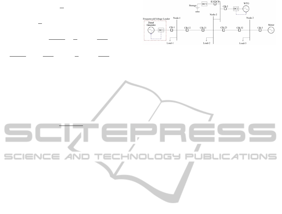
3 CONTROLLERS DESIGN
Figure 4 depicts the hybrid wind-diesel power sys-
tem architecture that has to be controlled, where DC
stands for distributed controller, CB stands for circuit
breaker and ILVDCB for intelligent low voltage dc
breaker (Minchala et al., 2012). The proposed control
strategy is composed of three distributed controllers,
each one with specific tasks:
1. DC1 implements two non-decoupled MPCs as a
first approach and two MRACs as a second ap-
proach that are in charge of regulating both grid
frequency and voltage amplitude. A diesel en-
gine is used as a prime mover which drags a syn-
chronous machine generator at a constant speed.
In an islanded configuration, the frequency is de-
termined by the mechanical speed ω
m
which is
provided by the diesel engine, while the volt-
age amplitude is set by the synchronous generator
field voltage.
2. DC2 is regarded with power generation control of
the WTG. In this first stage of investigation, an un-
constrained MPC for a limited range of the blade
pitch angle, β between 0 to 10 degrees, has been
designed.
3. DC3 controls a bi-directional dc−dc converter to
manage battery charge and discharge. A classic
PWM modulation control for the boost and buck
converters is used.
Figure 4: Hybrid wind-diesel power system architecture.
3.1 MPC Design
An integrator for reducing the steady-state error in
closed-loop has been added to MPC designs. The
augmented state-space model for diesel engine, SM
and WTG can be obtained as follows (Wang, 2009):
x
m
(k + 1) = A
m
x
m
(k) + B
m
u(k) (22)
y(k) = C
m
x
m
(k) (23)
∆x
m
(k + 1) = A
m
∆x
m
(k) + B
m
∆u(k) (24)
∆x
m
(k) = x
m
(k) − x
m
(k − 1) (25)
∆u(k) = u(k) − u(k − 1) (26)
x(k + 1) = Ax + B∆u(k) (27)
x(k) =
∆x
m
(k + 1)
y(k + 1)
(28)
A =
A
m
0
T
m
C
m
A
m
1
(29)
B =
B
m
C
m
B
m
(30)
y(k) =
0
m
1
x(k) (31)
where A
m
, B
m
, C
m
and x
m
represent the state matrix,
input matrix, output matrix and state vector of the
model, respectively. The augmented model in state
space that includes the integrator is represented by A,
B, x and ∆u. MPC uses this explicit model to predict
future trajectories of system states and outputs. This
prediction capability allows to solve optimal control
problems online, where prediction error and control
input action are minimized over a prediction horizon,
N
p
. The optimization yields to an optimal control se-
quence as input and only the first element from the se-
quence is used as the control signal for controlling the
system, while the whole optimization procedure is re-
peated over and over again in each sampling step. The
final aim of MPC is to provide zero output tracking
error with minimal control effort. Designing a MPC
with constraints is equivalent to solving a quadratic
programming problem in order to find the parameter
vector ∆U, which minimizes a cost function J subject
to inequality constraints as follows:
SMARTGREENS2013-2ndInternationalConferenceonSmartGridsandGreenITSystems
16

J = [R
s
− Fx (k
i
)]
T
− 2∆U
T
Φ
T
[R
s
− Fx (k
i
)]
+ ∆U
T
Φ
T
Φ + R
∆U (32)
γ ≥ M∆U (33)
u(k) = u(k − 1) + ∆u(k) (34)
F =
CA CA
2
CA
3
··· CA
N
p
T
(35)
Φ =
CB 0 ··· 0
CAB CB ··· 0
CA
2
B CAB ··· 0
.
.
.
.
.
.
.
.
.
.
.
.
CA
N
p
−1
B CA
N
p
−2
B ··· CA
N
p
−N
c
B
(36)
where R = r
w
I
N
c
×N
c
and r
w
is used as a tuning param-
eter for the desired closed-loop performance. R
s
is a
vector with length N
p
that allows a comparison be-
tween reference signal and model output, for which
case we assume that the reference, r(k) is constant
in the prediction horizon. M ∈ R
(
2N
p
+4N
c
)
×N
c
and
γ ∈ R
(
2N
p
+4N
c
)
×1
are adequate matrices that represent
every constraint in matrix form. Hildreth’s quadratic
programming algorithm has been used for updating
control law, whose processing time in every sampling
interval varies from less than 1 ms up to 35 ms (tic toc
instruction in Matlab), for a computer with an i7 2.3
GHz processor and 4 GB of RAM memory.
The following design parameters have been
adopted in the controllers:
• SM rotor speed controller: One of the aims of the
optimal integration of the diesel generator in the
microgrid is to reduce fuel consumption, giving
priority to the power coming from RES, in our
case from WTG. To achieve this objective, a hard
constraint on the control signal is imposed, al-
though softening this constraint will allow a better
performance as it will be shown in the simulation
results. The maximum tolerable frequency devia-
tion is ±3 and a hard constraint for y is imposed
according to this and finally neither accelerations
nor deaccelerations greater than 50% are allowed
and a constraint for this requirement is also con-
sidered.
N
p
= 20
N
c
= 10
r
w
= 20
0 ≤ u ≤ 0.8
−0.5 ≤ ∆u ≤ 0.5
0.97 ≤ y ≤ 1.03
• SM Voltage Output Controller. Due to a resistive
load has been considered in (9), a greater predic-
tion horizon than the preceding controller is con-
sidered, in order to assure system stability when
capacitive and inductive loads are connected into
the system. The only hard constraint is on the con-
trol signal, since it is not admissible to have val-
ues smaller than zero and greater than 2 in order
to avoid saturation phenomenoms in the SM mag-
netic circuit.
N
p
= 50
N
c
= 5
r
w
= 5
0 ≤ u ≤ 2
• WTG Power Controller. An unconstrained con-
troller for a pitch angle range from 0 to 10 de-
grees is used. A stable behaviour is reached out
of this range with this controller, although a de-
graded performance on settling time is obtained,
due to the nonlinear relationship between β and
generated power.
N
p
= 20
N
c
= 10
r
w
= 0.7
3.2 MRAC Design
The MRAC implements a closed-loop controller that
involves the parameters that should be optimized, in
order to modify the system response to achieve the
desired final value. The adaptation mechanism ad-
justs the controller parameters to match the process
output with the reference model output. The refer-
ence model is specified as the ideal model behavior
that the system is expected to follow. The design ap-
proach chosen for this work is the one using the Lya-
punov theory, presented in (Astrom and Wittenmark,
1995) and adapted here:
e = y
process
− y
re f erence
= G
p
× u − G
re f
× u
c
(37)
where e, y
process
, y
re f erence
, G
p
, u, G
re f
and u
c
repre-
sent the error, process output, reference output, pro-
cess model, process input, reference model and con-
troller signal, respectively. For a second order system,
the implemented MRAC scheme has two adaptation
parameters: adaptive feedfoward gain θ
1
and adap-
tive feedback gain θ
2
. These parameters will be up-
dated to follow the reference model. Then, the input
is rewritten in terms of the adaptive feedforward and
adaptive feedback gains as follows:
Model-basedControlApproachesforOptimalIntegrationofaHybridWind-dieselPowerSysteminaMicrogrid
17

u = θ
1
× u
c
− θ
2
× y
process
(38)
The Lyapunov stability theorem establishes the
following: If there exists a function V : R
n
→ R be-
ing positive definite and its derivative:
dV
dT
=
∂V
T
∂x
dx
dt
=
∂V
T
∂x
f (x) = −W (x) (39)
is negative semidefinite, then the solution x(t) = 0 to
dx
dt
= f (x) f (0) = 0 (40)
is stable. If
dV
dt
is negative definite the solution will be
asymptotically stable. V denotes the Lyapunov func-
tion for the system. If
dV
dt
< 0 and V (x) → ∞ when ||x|| → ∞ (41)
the solution is globally asymptotically stable.
To design an MRAC controller using Lyapunov
theory, the first step is to derive a differential equa-
tion for the error that contains the adaptation param-
eters. Then, a Lyapunov function and an adaptation
mechanism need to be established to reduce the error
to zero. The Lyapunov derivative function
dV
dt
is usu-
ally negative semidefinite. Therefore, determining the
parameter convergence is necessary to establish per-
sistently excitation and uniform observability on the
system and the reference signal (Nagrath and Gopal,
2008). The proposed Lyapunov function is quadratic
in tracking error and controller parameter estimation
error because it is expected that the adaptation mech-
anism will drive both types of errors to zero. From the
equation error dynamics (42) the proposed Lyapunov
function can be chosen as (43):
de
dt
= −
1
a
1r
d
2
e
dt
2
−
a
0r
a
1r
e +
b
r
a
1r
(θ
1
− 1) u
c
−
b
r
a
1r
θ
2
y
p
(42)
V (e,θ
1
,θ
2
) =
1
2
a
1r
e
2
+
b
r
γ
(θ
1
− 1)
2
+
b
r
γ
(θ
2
)
2
(43)
where b
r
, γ and a
1r
> 0.
Equation (43) will be zero when the error is zero
and the controller parameters are equal to the de-
sired values. The above Lyapunov function is valid
if the derivative of this function is negative. Thus, the
derivative of (44) is:
˙
V = a
1r
e
de
dt
+
b
r
γ
(θ
1
− 1)
dθ
1
dt
b
r
γ
θ
2
dθ
2
dt
(44)
Substituting (42) in the above equation and rear-
ranging the similar terms, equation (45) is obtained:
˙
V = −e
d
2
e
dt
2
− a
0r
e
2
+
1
γ
(b
r
θ
1
− b
r
)
dθ
1
dt
+ γu
c
e
+
1
γ
(b
r
θ
2
)
dθ
2
dt
− γy
process
e
(45)
If the adaptation parameters are updated as:
dθ
1
dt
= −γu
c
e and
dθ
2
dt
= γy
process
e (46)
then,
˙
V = −e
d
2
e
dt
2
− a
0r
e
2
(47)
It can be seen that (47) is negative semidefinite
which implies V (t) ≤ V (0). This ensures that e, θ
1
and θ
2
are bounded. Since a
1r
> 0, a
0r
> 0 and u
c
is bounded then y
re f erence
is bounded and therefore
y
process
= e + y
re f erence
is bounded as well. From the
boundedness and convergence set theorem it can be
concluded that the error e will go to zero (Nagrath
and Gopal, 2008).
To overcome the limitations of the simple MRAC
structure (smaller fault accommodation threshold
than the MRAC in combination with other structures),
a classical PID controller expressed in the form
PID = K
p
+
K
i
s
+ K
d
s (48)
is introduced in the feedforward part of the simple
MRAC scheme. The PID parameters were obtained
by using a genetic algorithm pattern search to track
the desired system trajectory with the Matlab
R
Op-
timization Toolbox. The desired closed-loop behav-
ior of the system is established through the model
reference trajectory when there is no fault in the sys-
tem. The parameters that need to be established for
the desired optimization are shown in Table 2.
Table 2: Matlab
R
Optimization Toolbox parameters.
Parameters Value
Step initial value 0
Step final value 1
Step time 0
Rise time 6s
% Rise 90
Settling time 9s
% Settling 5
% Overshoot 20
% Undershoot 2
SMARTGREENS2013-2ndInternationalConferenceonSmartGridsandGreenITSystems
18
Then, the genetic algorithm (GA) obtains the best
parameter optimization (see Table 3). The desired re-
sponse is introduced in terms of rise time, stabiliza-
tion time and overshoots.
Table 3: Optimized PID parameters using GA.
Parameter PID
K
p
3.8748
K
i
2.6471
K
d
1.9347
The MRAC has an adaptation learning rate γ =
0.99 for simulations to be presented in next section.
4 SIMULATION RESULTS
The system architecture shown in Fig. 4 was imple-
mented in Matlab/Simulink
R
. System parameters are
shown in Table 4. Three different controllers for the
diesel engine generator were tested, the first one is
the baseline diesel engine speed and voltage control
that Matlab has in its library, i.e. governor and PI
controller for the rotor speed control and IEEE type
1 AVR for maintaining the voltage amplitude of the
microgrid. The second control approach tested is the
MPC described in sub-section 3.1 and the third one
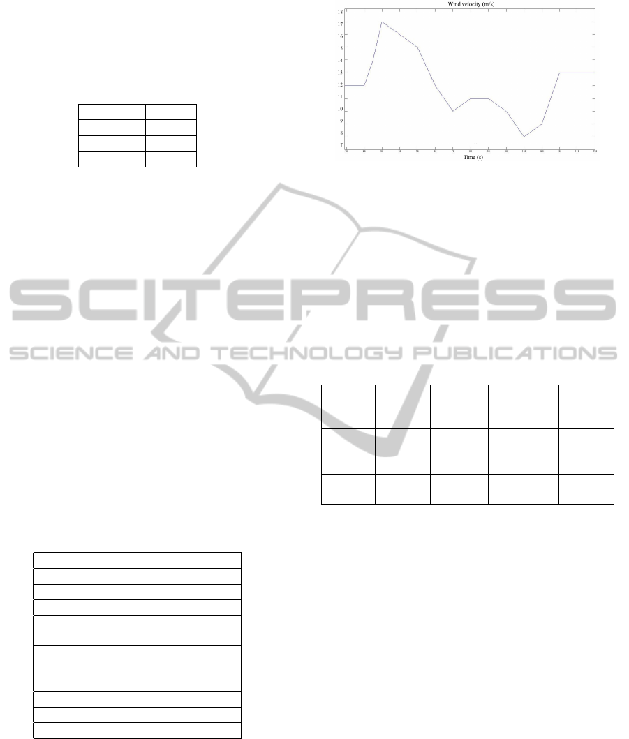
is the MRAC described in sub-section 3.2. Variable
wind speed was used during the simulation, whose
velocity in every time instant of the simulation is de-
picted in Fig. 5.
Table 4: Hybrid wind-diesel system parameters.
Parameter Value
SM power 3 MVA
Grid voltage 220 V
Grid frequency 60 Hz
WT nominal mechanical
output
1.5 MW
WT max power at base
wind speed
0.85
Base wind speed 12 m/s
Load-1 2 MW
Load-2 0.5 MW
Load-3 0.4 MW
Fig. 6 shows the simulation results when the MPC
with softened constraint is used and Fig. 7 shows the
simulation results for the three control approaches.
The exact same events were tested in every case: (i)
when system is in steady state and WTG is off, then
suddenly WTG is turned on (after 12 seconds have
elapsed in the simulation) and the battery starts charg-
ing from 50% of SOC; (ii) when 50 seconds have
Figure 5: Wind velocity during the simulation.
elapsed, Load-2 is connected whose power consump-
tion is 0.5 MW; and (iii) a three-phase fault of 0.5 s of
duration is present in node-3 when 100 s of the simu-
lation time have elapsed. CB-32 disconnects every-
thing that is at its right side for isolating the fault.
MPC and MRAC show a much better performance
than the baseline controller and also they offer several
advantages over it, as summarized in Table 5.
Table 5: Advantages of MPC and MRAC over classic con-
trollers for DG integration in the microgrids.
Robust-
ness
Fault-
Tolerance
Constraints
Manage-
ment
Scalabi-
lity
MPC High Yes Yes High
MRAC Very
High
Yes No High
Classic
control
Low No No Low
A maximum power extraction from the WTG is
pretended by this network configuration through pitch
angle control by a PID controller when the baseline
controller is used and unconstrained MPC when MPC
and MRAC are used in the diesel generator. Different
wind speeds are present, so 1 MW of power reference
is set in the WTG, and the balanced load (total load
- WTG power) is fed by the diesel engine. Battery
is charging from its initial SOC until full and is being
fed by an ac to dc converter with PWM control, whose
duty cycle has been set to 1.
5 CONCLUSIONS
A distributed MPC strategy and a MRAC with a PID
controller whose parameters were tuned using a GA
have been developed in this paper for an islanded mi-
crogrid configuration which integrates the wind tur-
bine generator and diesel engine generator for more
efficient electricity generation in the framework of
smart grids. Compared with a baseline controller, the
Model-basedControlApproachesforOptimalIntegrationofaHybridWind-dieselPowerSysteminaMicrogrid
19
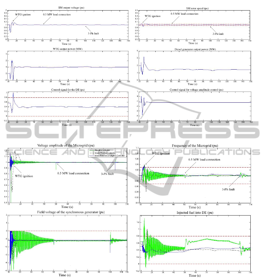
Figure 6: System simulation with MPC controlling the diesel generator and the WTG.
Figure 7: Performance comparison for the three different control approaches.
developed controllers, MPC and MRAC, achieved a
better performance in both voltage and frequency re-
sponses. Softening the control signal constraint of the
diesel engine during WT ignition offered an improved
response in frequency control. Hard constraint on the
control signal of the diesel engine allows setting max-
imum fuel consumption and prioritizes energy gener-
ated by RES. A major advantage of MPC is its ability
to integrate constraints in the design that can be used
in a future work for FTC capabilities. On the other
hand the MRAC has an inherent capacity to accom-
modate perturbations and faults and direct physical
interpretation, and it is relative easy for implemen-
tation. Howerver, the use of only this type of con-
troller has certain limitations. For this reason, it is
normally to combine MRAC with other structures in
order to guarantee the system performance, to reduce
the unknown model dynamics, disturbances, to have
a better transient behavior, etc. It is important to re-
mark that the Lyapunov theory implemented to design
the MRAC guarantees closed-loop stability with also
fault-tolerant capabilities.
SMARTGREENS2013-2ndInternationalConferenceonSmartGridsandGreenITSystems
20

REFERENCES
Abdal, F., Abbas, R., and Abdulsada, M. A. (2010). Sim-
ulation of wind-turbine speed control by matlab. In-
ternational Journal of Computer and Electrical Engi-
neering, 2(5):912–915.
Abdin, E. and Xu, W. (2000). Control design and dynamic
performance analysis of a wind turbine-induction gen-
erator unit. IEEE Transactions on Energy Conversion,
15(1):91–96.
Astrom, K. and Wittenmark, B. (1995). Adaptive Control.
Addison-Wesley Publishing Company, 2nd edition.
Carter, R., Cruden, A., Hall, P., and Zaher, A. (2012).
An improved lead acid battery pack model for use in
power simulations of electric vehicles. IEEE Transac-
tions on Energy Conversion, 27(1):21–28.
Chiasson, J. and Vairamohan, B. (2005). Estimating the
state of charge of a battery. IEEE Transactions on
Control Systems Technology, 13(3):465–470.
Fuchs, E. F. and Masoum, M. A. (2011). Analyses and de-
signs related to renewable energy systems. In Power
Conversion of Renewable Energy Systems, pages 557–
687. Springer US.
Fusco, G. and Russo, M. (2008). Adaptive voltage regulator
design for synchronous generator. IEEE Transactions
on Energy Conversion, 23(3):946–956.
Fusco, G. and Russo, M. (2012). Nonlinear control design
for excitation controller and power system stabilizer.
Control Engineering Practice, 19(3):243–251.
Gentile, T. J. (2009). Smart grid a necessary component in
the remaking of america. IEEE-USA Annual Meeting.
Hiyama, T. (2011). Intelligent Automatic Generation Con-
trol. CRC-Press.
Jiang, Z., Li, F., Qiao, W., Sun, H., Wan, H., Wang, J., Xia,
Y., Xu, Z., and Zhang, P. (2009). A vision of smart
transmission grids. pages 1–10.
Jugo, J. (2002). Discretization of continuous time-delay
systems. In Proceedings of the 15th IFAC World
Congress, 2002, pages 117–122.
Kassem, A. M. (2012). Robust voltage control of a stand
alone wind energy conversion system based on func-
tional model predictive approach. International Jour-
nal of Electrical Power and Energy Systems, 41:124–
132.
Kassem, A. M. and Ali, M. Y. (2011). Robust control of an
isolated hybrid winddiesel power system using linear
quadratic gaussian approach. International Journal of
Electrical Power and Energy Systems, 33:1092–1100.
Kini, A. and Yaragatti, U. (2006). Modelling and simula-
tion of a wind/diesel hybrid power system. In Pro-
ceedings of the IEEE International Conference on In-
dustrial Technology, ICIT, pages 1670–1675.
Kuang, B., Wang, Y., and Tan, Y. L. (2000). An h
∞
con-
troller design for diesel engine systems. In Proceed-
ings of the International Conference on Power System
Technology, volume 1, pages 61–66.
Kumar, B., Mishra, S., Bhende, C., and Chauhan, M.
(2008). Pi controller based frequency regulator for
distributed generation. In Proceedings of the TEN-
CON - IEEE Region 10th Conference, pages 1 –6.
Lee, S.-H., Yim, J.-S., Lee, J.-H., and Sul, S.-K. (2008).
Design of speed control loop of a variable speed diesel
engine generator by electric governor. pages 1–5.
Minchala, L., Garza, L., and Calle, E. (2012). An intelli-
gent control approach for designing a low voltage dc
breaker. Number 4, pages 163–166.
Munoz-Aguilar, R., Doria-Cerezo, A., Fossas, E., and Car-
doner, R. (2011). Sliding mode control of a stand-
alone wound rotor synchronous generator. IEEE
Transactions on Industrial Electronics, 58(10):4888–
4897.
Nagrath, I. and Gopal, M. (2008). Control Systems En-
gineering. Anshan Ltd Press, United Kingdom., 5th
edition.
Schwaegerl, L., Tao, J.P.; Lopes, A., Madureira, P., Mancar-
ella, A., Anastasiadis, N., Hatziargyriou, and Krkol-
eva, A. (2009). Report on the technical, social, eco-
nomic, and environmental benefits provided by micro-
grids on power system operation.
Vandoorn, T., Meersman, B., Degroote, L., Renders, B., and
Vandevelde, L. (2011). A control strategy for islanded
microgrids with dc-link voltage control. IEEE Trans-
actions on Power Delivery, 26(2):703–713.
Vechiu, I., Camblong, H., Tapia, G. B., and Dakyo, C. N.
(2004). Dynamic simulation model of a hybrid power
system: Performance analysis. 2004 European Wind
Energy Conference.
Wang, L. (2009). Model Predictive Control System Design
and Implementation Using MATLAB. Springer Pub-
lishing Company, Incorporated, 1st edition.
Zeng, L. and Hu, G.-D. (2010). Discretization of
continuous-time systems with input delays. Acta Au-
tomatica Sinica, 36(10):1426–1431.
Model-basedControlApproachesforOptimalIntegrationofaHybridWind-dieselPowerSysteminaMicrogrid
21
