
New ‘Spider’ Convex Hull Algorithm
For an Unknown Polygon in Object Recognition
Dmitriy Dubovitskiy
1
and Jeff McBride
2
1
Director, Oxford Recognition Ltd, Cambridge, U.K.
2
Medical Device Specialist, Liverpool, England and Cork, Ireland
Keywords:
Convex Hull, Pattern Analysis, Segmentation, Object Recognition, Image Morphology, Machine Vision,
Computational Geometry.
Abstract:
Object recognition in machine vision system and robotic applications has, and is still, an important aspect
in automation applications of our everyday life. Although there are a lot of machine vision algorithms there
are not always entirely clear and unified solutions for particular applications. This paper is concerned one
particular step in image interpretation connected with the convex hull algorithm. This new approach to the
process of convex hull step of object recognition offers a wide range of application and improves the accuracy
of decision making on later steps. The challenging fundamental problem of computational geometry is offering
the solution in this work to solve convex hull procedure for an unknown image polygon. The unique feature
of the offered new approach is the flexible intersection of all convex set points of an object on a digital
image. The convex combination points remains unknown and allow us to get the real vector space. The image
segmentation algorithm and decision making procedure working in conjunction with this new convex hull
algorithm will take robotic applications to a higher level of flexibility and automation. We present this unique
procedure for automating and a new model of image understanding.
1 INTRODUCTION
The modern development in digital camera manu-
factures brings new potential for digital image pro-
cessing. The fast growing image capturing CCD ar-
ray development is capable of generating ever larger
amounts of data for processing. Storage facilities
have developed to nearly unlimited capacity, to the
extent that a human is unable to process these vol-
umes of data manually/visually. With this increased
capability in image capture and storage all of industry
and science will, in future, have to relay on stable and
robust robotic potential to interpret the acquired data.
Throughthis innovationBioinformatic, visual naviga-
tion, quality control and medical diagnostics are com-
ing to the new stage of automatic image recognition.
If we consider that each image consist of one or
several objects each of which has certain features.
The set of features that are recognisable to the human
eye makes us to acknowledge the nature of the image
that is in front of a camera. In computer memory there
is fundamental connectivity problem for the compil-
ing of the identified features into a recognisable image
with the features contained within a defined border
line. This process of dividing an image into meaning-
ful regions or segments called segmentation. Due to
the nature of the image/features and/or the light con-
dition under which the image is captured,a particular
object’s features could vary from one side of an object
to another. This paper offersa new universal approach
to the segmentation task and/or the selection of Re-
gions Of Interest (ROI) for accurate border matching.
In absence of no complete and unique theoretical
model available for simulating human object recog-
nition, we consider a unified concept in this paper for
convexhull algorithm as a componentof image analy-
sis which involves the use of digital image processing
methods in attempt to provide a machine interpreta-
tion. The colour, morphological or pattern identifiers
for automatic image recognition could vary and/or
combine in this approach. This includes the possi-
bility of combining the set of identifiers to provide a
new level of stability and robustness in automatic ob-
ject recognition and decision making procedures. The
offered novel computational geometry roots has the
appearance of a virtual spider net formation on an im-
age space, so we are calling the new algorithm ”Spi-
der convex hull”. The same approach could be easily
311
Dubovitskiy D. and McBride J..
New ‘Spider’ Convex Hull Algorithm - For an Unknown Polygon in Object Recognition.
DOI: 10.5220/0004368703110317
In Proceedings of the International Conference on Biomedical Electronics and Devices (MHGInterf-2013), pages 311-317
ISBN: 978-989-8565-34-1
Copyright
c
2013 SCITEPRESS (Science and Technology Publications, Lda.)

extended to multidimensional space, but for simplic-
ity in this paper we present C++ code and graphical
illustration for 2D application. This suggested solu-
tion is universal and can be used in wide range of
machine vision applications. This new level of au-
tomation provides possibilities to improve the quality
of people life in a multitude of potential applications.
2 IMAGE RECOGNITION
In this section, we consider the applied procedures
that are necessary during object recognition. These
procedures are adaptive and have no binding to a par-
ticular range of applications. A typical colour im-
age consists of mixed RGB signals. A grey-tone im-
age appears as a normal black and white photograph.
However, on closer inspection it may be seen that it
is composed or a large number of individual picture
cells or pixels. In fact, a digital image is an [x, y]
array of pixels. One can get a better feel for the dig-
ital limitations of such a digitised image by zooming
into a section of the picture that has been enlarged so
that the pixels can be examined individually. It is then
easy to appreciate that each pixel contains z grey level
digitalisation. This level will include a certain amount
of noise and so it is seldom worth digitising more
accurately than 8 bits of information per pixel. The
number of these levels depends on the signal-to-noise
ratio of the image capture devise and the analogue-to-
digital converter. Modern digital cameras can store up
to 24 bits per pixel. Note, that if the human eye can
see an object in a digitised image of practical spatial
and grey-scale resolution, then, it is in principle pos-
sible to devise a computer algorithm to do the same
thing. In a human eye, image points are organised
into a photosensitive matrix or array where each point
can be enumerated in terms of coordinates x and y.
The value of each isolated point can be represented
by value of a function I with coordinates x and y.
Here, x can be taken to represent the horizontal axis
and y the vertical axis. Video information is stored
in the same way, i.e. in terms of the function I (x, y)
(Rosenfeld, 1982; R.O. Duba, 1973). The colour con-
tent(s) of an image is very important and contributes
significantly to the image processing operations re-
quired and the object recognition methodologies ap-
plied (Freeman, 1988). In the case of medical imag-
ing in general, colour processing and colour interpre-
tation is critical to the diagnosis of many conditions
and the interpretation of the information content of an
image by man and machine. Colour image processing
is become more and more important in object analy-
sis and pattern recognition. The numerous and non-
related algorithms for understanding two- and three-
dimensional objects in a digital image have and con-
tinue to be researched in order to design systems that
can provide reliable automatic segmentation, object
detection, recognition and classification in an inde-
pendent environment (e.g. (E.R.Davies, 1997), (Free-
man, 1988), (Louis and Galbiati, 1990) and (Snyder
and Qi, 2004)). In relation to an object’s shape, size,
morphological similarity, texture and continuity these
tasks can be very challenging.
Several conditions needto be considered in the de-
velopment of any machine vision system: 1) the tar-
get resolution or contrast 2) The structural algorith-
mic approach including object representation 3) What
type of hardware would be suitable to reach speed and
accuracy For example, optical microscopy involves
the use of image processing methods that are often
designed in an attempt to provide a machine inter-
pretation of a biological image, whereby some deci-
sion criterion to be applied, such that a pattern of bi-
ological significance can be recognised (Russ, 1990),
(M.A.Hornish and R.A.Goulart, 2008).
Associations between the features and an object
pattern attributes forms automatic learning context for
knowledge data base (Dubovitskiy and Blackledge,
2009),(Dubovitskiy and Blackledge, 2008), whereby
the representation of the object is assembled into the
feature vector (Grimson, 1990), (Ripley, 1996). The
knowledge data base depends on establishing equiva-
lence relations that express a fit of evaluated objects
to a class with independent semantic units. Where
by assigning a particular class to an object the pattern
recognition task is accomplished.
2.1 Practical Image Recognition
Implementation
Practical image recognition systems generally contain
several stages in addition to the recognition engine it-
self. Image pre-processing is used for adjusting the
artefacts after the operation of an image acquisition
system. We consider the following sub-tasks.
Low brightness and Contrast. The correction of
brightness and contrast is usually a pre-processing
procedure, after which, the image looks clearer and
more precise. Nevertheless, it is necessary to note,
that such a correction does not provide any additional
information of value to procedures such as feature ex-
traction or boundary detection for example. The exis-
tence or otherwise of spatial frequencies is indifferent
to whether the map of the image is contrast stretched
or not. In current applications, the brightness and
contrast of the images used is sufficiently good for
the system to exclude this pre-processing procedure
BIODEVICES2013-InternationalConferenceonBiomedicalElectronicsandDevices
312

although in other applications of the algorithm, this
may be a necessary requirement. Image graininess
Some types of images can have a grainy structure -
often due to the nature or features of the image acqui-
sition system. It is a typical problem in those cases
where it is necessary to acquire an image with max-
imal resolution. The main problem with processing
coarse-grained maps is related to the in-practicality of
detecting the boundaries, i.e. boundaries are detected
that are associated with grains instead of the contours
of objects. A typical solution consists of smoothing
the image using minor diffusion in which the bound-
aries of the grains become fuzzy and diffused with
each other, while the contours of object remain (al-
beit over a larger spatial extent). A similar effect can
be obtained using the median filter. However, use
of the median filter includes an inevitable loss of in-
formation characterised by shallow details (i.e. low
grey level variability). In this thesis, the Wiener fil-
ter (Wiener, 1949)is used which is computational ef-
ficient, robust and optimal with regard to grain diffu-
sion and information preservation. This filter elimi-
nates high-frequency noise and thus does not distort
the edge of objects. Other solutions include prelimi-
nary de-zooming for the purpose decreasing grit size
up to and including the size of a separate pixel. Such a
method involves loss of shallow details however, and
thus, the size of the map (and accordingly, the pro-
cessing time) decreases. The other advantage of such
a method concerns hardware implementation, e.g. ap-
plication of a nozzle to an optical system. In situations
where the methods described here are unacceptable,
it is necessary to use a more complex quality detector
for boundary estimation which is discussed below.
Geometrical Distortions. In practice, the most im-
portant geometrical distortions are directly related to
character of an image acquisition. In the majority of
cases is possible to use a standard video camera as
the image sensor. However, the majority of industrial
production specifications for video systems use an in-
terlaced scan technique for image capture. This leads
to ‘captured lines’ in the image of both even and odd
types which leads to a time delay between neighbour-
ing lines (equal to half the acquisition time frame). If
there is a moving object in the field of view, then its
position on even and odd lines will be different - the
picture of the object will be ‘washed’ in a horizon-
tal direction. This is a particularly important problem
in the extraction of edges. In this case, it is impossi-
ble to bleed the verticals. The elementary solution to
this problem is to simply skip the even or odd frames
(preferably the even frames as the odd frames consist
of later information). Another way is to handle even
and odd frames separately providing the processing
speed allows for practical implementation. If this is
not possible, it is necessary to use a video system with
non interlaced scanning.Over the past few years, with
the development of digital video and engineering the
capability has emerged to use digital video cameras
with high resolution. A singular advantage of this is
the uniformity of the picture without the distortions
discussed above. However, the video RGB of matri-
ces need to be analysed to avoid inter-colour distor-
tions. These distortions are connected to the geomet-
rical distribution of the RGB cells on the surface of
a CCD matrix and can be seen when increases in the
size of the digital are introduced. Special filters need
to be designed that can be used in the prevention of
this kind of distortion
Edge Detection. has gone through an evolution span-
ning more then 20 years. Two main methods of edge
detection have been apparent over this period, the first
of these being template matching and the second, be-
ing the differential gradient approach. In either case,
the aim is to find where the intensity gradient mag-
nitude g is sufficiently large to be taken as a reliable
indicator of the edge of an object. Then, g can be
thresholded in a similar way to that in which the inten-
sity is thresholded in binary image estimation. Both
of these methods differ mainly in that they proceed to
estimate g locally. However, there are also important
differences in how they determine local edge orienta-
tion, which is an important variable in certain object
detection schemes.
Each operator estimates the local intensity gradi-
ents with the aid of suitable convolution masks. In
a template matching case, it is usual to employ up
to 12 convolution masks capable of estimating lo-
cal components of the gradient in the different direc-
tions. Common edge operators used are due to Sobel
(J.M.S.Perwitt, 1970), Roberts (L.G.Roberts, 1965),
Kirsch (R.A.Kirsh, 1971), Marr and Hildreth (Marr
and E.Hildreth, 1977), Haralick (R.M.Haralick, 1980;
R.M.Haralick, 1984), Nalwa and Binford (Nalwa and
Binford, 1986) and Abdou and Pratt (Abdou and
W.K.Pratt, 1979). In the approach considered here,
the local edge gradient magnitude or the edge magni-
tude is approximated by taking the maximum of the
responses for the component mask:
g = max(g
i
: i = 1ton)
where n is usually 8 or 12. The orientation of the
boundary is evaluated in terms of the number of a
mask giving maximal value of amplitude of a gradi-
ent.
The integration of local operands into convex hull
algorithm is the way forward to isolate ROI or in par-
ticular cases accuracy identify object location. The
New'Spider'ConvexHullAlgorithm-ForanUnknownPolygoninObjectRecognition
313

texture analysis is the next step of image recognition.
The combination of edge detection and texture analy-
sis into convex hull offer the new accurate and reliable
stage of image processing tool.
3 TECHNOLOGY OVERVIEW
In this section, we briefly review the currently avail-
able convex hull algorithms and components associ-
ated with the application. The common practice in
segmentation and image recognition technics is to use
procedure call binarisation. The principal question is
what does comes comes first segmentation or recog-
nition? The answer is a combination of both through
the use of the convex hull approach.
The first task in common solution is to remove
points with small amplitude of a local gradient of
brightness with the purpose of separating points of
a contour from textures, shallow details and noise.
There are two cases to the segmentation algorithm:
(i) Pixels similarities based approach
(i) Surface discontinuities based approach
The first way is to select some value of a threshold
binarisation TR and to remove points with amplitude
of a gradient |g| < TR. Some of the thresholding pro-
cessing needs to be considered a priori.
The main problem in defining the value of a
threshold TR say, is that it should be different for dif-
ferent images. Moreover, if the objects on the image
have different brightness, the value TR should be dif-
ferent for different areas of the image. The solution is
usually employed through a method of adaptive bina-
rization, based on calculating the value of a threshold
TR for small areas of the image (size 88.. 1212) - so-
called block binarisation. For each area, the average
value I
0
of brightness amplitude is evaluated and then
the value of a threshold is calculated as follows:
TR = k ∗ I
0
where k = 1.2.. 1.8 - binarisation coefficient. Change
in the value of k are invalid when considerable
changes in the quality of an extracted contour occur
(as against the level of a threshold TR), and the value
k = 1.5 can be adopted for the overwhelming majority
of the images.
Another modification of this method involves the
calculation of the level of a threshold separately for
different boundary orientations. This prevents the
deletion of important details close to brighter objects.
However, this method requires more computing cost
(as it is necessary to compute the local histograms but
allow for an increased value of a threshold TR without
loss of essential details and, as a corollary, reduction
in the quantity of false points.
In addition to the thresholding methods one can
employ multi-region based segmentation. Regions,
which are continuous, are simply connected clusters
of pixels which are mutually exclusive and exhaustive
(i.e. a pixel can only belong to a single region and all
pixels have to belong to some region). A region may
support a set of predicates; however, an adjacent re-
gion cannot support the same set of predicates. The
advantages of using a region-based segmentation are:
(1) there are far fewer regions than pixels in an im-
age, thus allowing data compression; and (2) regions
are connected and unique. The disadvantages of the
method are: (1) assumptions are made about the uni-
formity of image features; (2) a region could be erro-
neously considered to be a single surface; (3) surface
properties or such as reflection can produce regions of
noise.
There are two principal approaches to region-
based segmentation which are discussed below
1. Region Growing. Initially each pixel can be con-
sidered to be a separate region. Adjacent regions
are merged if they have similar properties (such as
grey-level). This merging process continues until
no two adjacent regions are similar. The similarity
between two regions is often based upon simple
statistics such as the variance measure or the range
of grey-levels within the regions. Region-based
segmentations are described in (Brice and Fen-
nema, 1970), (Yakimovsky and Feldman, 1973),
(Feldman and Yakimovsky, 1974), (C.A.Harlow
and S.A.Eisenbeis, 1973).
2. Region Splitting. Initially the image is regarded
as being a single region. Each region is recur-
sively subdivided into subregions if the region is
not homogeneous. The measure for homogene-
ity is similar to that for region growing. Robert-
son et al. subdivided a region either horizontally
or vertically if the pixel variance in the region is
large (P.W.Swain and Fu, 1973). Others - e.g.
(J.M.S.Perwitt, 1970) - use the bimodality of his-
tograms to split regions. This is referred to as the
mode method and has been extended (Ohlander,
1975; Price and Reddy, 1978) to use multiple
thresholds from the histogram of the region. How-
ever, as discussed above, a histogram gives global
information about a region. Using this method,
some pixels can be assigned a wrong label and
therefore pre- and post-filtering is required (Oh-
lander, 1975).
Growing regions is a more difficult task then
region splitting. However, region splitting, using
the method described in (P.W.Swain and Fu, 1973)
BIODEVICES2013-InternationalConferenceonBiomedicalElectronicsandDevices
314

(J.M.S.Perwitt, 1970), can lead to the generation of
more regions than required. Some region merging
at the end of the splitting phase is required. A
large group of segmentation techniques is used tex-
ture analysis. In the previous section, we described
methods for image segmentation based on the grey-
level properties of objects. These methods generally
work well for man-made objects which usually have
a smooth grey-level surface. We observe a textured
region as being homogeneous, although the intensity
across the region may be non-uniform. This leads to
the intensity-based segmentation methods to produce
results which do not match with our perception of the
scene.
Texture is important not only for distinguishing
different objects but also because the texture gradient
contains information describing the objects depth and
orientation. Texture can be described by its statistical
or structural properties (B.Lipkin and A.Rosenfeld,
1970). A texture surface having no definite pattern
is said to be stochastic, while texture with a defi-
nite array of sub-patterns is said to be determinis-
tic. These textured surfaces can then be described
by some placement rule for the pattern primitives. In
reality, deterministic texture is corrupted by noise so
that it is no longer ideal; this is referred to as the ob-
servable texture. If the pattern making up the deter-
ministic texture itself has subpatterns, then these are
called microtextures and the larger patterns are called
macrotextures. One of most powerful texture mea-
sures is the fractal geometry. The main idea is that
fractal properties can be used like individual features
of an image or part of an image. One of the ways
to achieve adaptive thresholding has been patented in
a previous publication (Dubovitskiy and Blackledge,
2012).
Segmentation should be invariant to indexing al-
gorithms. The indexing phase has until recently been
almost entirely ignored. In practice, emphasis of the
recognition procedure has been placed on producing
reliable correspondence algorithms (Grimson, 1990).
The results of all these methods combined are not suf-
ficient to automatically segment complex image struc-
tures such as medical images e.g. a cervical smear.
This can be achieved by using a local estimation and
a special suite of algorithm(s) developed with convex
hull to allow us to produce a successful result
Currently available convex hull algorithms could
be found (Andrew, 1979), (Brown, 1979). Some
Quickhull algorithms and a randomised incremental
program is available (C. B. Barber and Huhdanpaa,
1993). Let consider a problem of the object form,
where Q
k
are finite sets and G
k
(x, y) represents a lin-
ear objective function. Then the optimal solution for
convex hull obtains the value of the following:
Q
k
= max
k
∑
G
k
(x, y)
The decomposition optimisation is possible and it
is equivalent to filter primal objective of the convex
hulls of the individual feasible sets. Most of them are
based on the decomposition of linear cost function.
However, due to either the lighting of the object, ex-
posure condition or the object positioning the object
properties can vary, making the application of the al-
gorithm not possible. Therefore there is a strong need
for local micro decision making about the object bor-
der.
4 CONVEX HULL ALGORITHM
‘SPIDER’
Suppose we have an image which is given by a func-
tion f(x, y) and contains some object described by
a set (a feature vector that may be composed of in-
teger, floating point and strings) S = {s
1
, s
2
, ..., s
n
}.
We consider the case when it is necessary to define a
sample which is somewhat ‘close’ to this object. As
in the previous algorithm described, after binarisation
of image I(r, c) we acquire a two dimensional binary
representation of an object on the index map I
bin
(r, c)
which has the same dimension as the initial image
(1 corresponds to the presence of an edge or body
of the object and 0 corresponds to the background of
the image). Let us consider the task of obtaining the
co-ordinates of a convex polygon. This task is given
in the MATLAB function ‘Qhull’. The algorithm ap-
plied in this paper differs from that of MathWorks Inc
one in terms of its simplicity, reliability and fast com-
putation. The reason is that a number of cycles per-
formed is limited and equal to the total border length
of the object.
The main idea can be presented in terms of a ‘Spi-
der’, which creeps on a wall of the map and pulling
behind itself a thread. This thread is attached to the
object. At the ‘point of curvature’ the thread stores
the co-ordinates of the outer polygonal point. Each
thread could be considered as a line on an image. We
can propagate along a line of any local function. Thus,
the path on the perimeter around the object provides
the co-ordinates of all the outer polygonal points as
shown in Figure 1
Let us consider the algorithmic solution of this
task. For initial conditions we should select a position
of a thread without bends. Clearly, this will be along
one of four boundaries of the image. The direction
of a detour and the selection of the initial conditions
New'Spider'ConvexHullAlgorithm-ForanUnknownPolygoninObjectRecognition
315
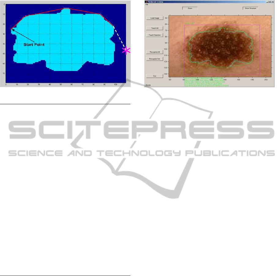
Figure 1: Obtaining co-ordinates for Convex hull.
{NListDotsX[02*((maxX-minX)+(maxY-minY))] //Object’s
NListDotsY[02*((maxX-minX)+(maxY-minY))]}//dots list
ListDotsX[0]=StartX; // Sets the initial co-ordinates
ListDotsY[0]=StartY; // for other end of a thread
int nc=0,x4,y4,Mx4,My4;
double fi,cs,sn,step,r,RR,bz,sz;
for(nt=0;nt<(2*((maxX-minX)+(maxY-minY)));nt++){//Begin
fi=atan2(NListDotsY[nt]-StartY,...// creeps around
NListDotsX[nt]-StartX); // object
RR=sqrt(pow((NListDotsX[nt]-StartX),2)+...
+pow((NListDotsY[nt]-StartY),2));
cs=cos(fi);
sn=sin(fi);
if (fabs(sn)>fabs(cs)){ //Calculation
bz=fabs(sn); //the step length
sz=fabs(cs);
}else{
bz=fabs(cs);
sz=fabs(sn);
}
step=sqrt(pow(((sz*(1-bz))/bz),2)+pow((1-bz),2))+1;
for (r=0;r<=RR;r+=step){ // Searching for objects
x4=round((double)StartX + r*cs);//in way of thread
y4=round((double)StartY + r*sn);
if (*(ppg + x4*h + y4) == 1){
Mx4=x4; // saving last coordinate
My4=y4; // in temporary variables
}
}
if (((Mx4!=StartX)&&(My4!=StartY)) || //Stop check
((Mx4==StartX)&&(Mx4==NListDotsX[nt])&&
(Mx4!=NListDotsX[nt+1]))||((My4==StartY)&&
(My4==NListDotsY[nt])&&(My4!=NListDotsY[nt+1]))){
StartX=Mx4; // Assign new start co-ordinates
StartY=My4;
nc=nc++;
ListDotsX[nc]=StartX; // Saving list Convex hull
ListDotsY[nc]=StartY; // coordinates
}
}
Figure 2: C++ algorithm for Convex Hull.
do not depend on to the aforementioned conditions.
In the example considered here, the detour is clock-
wise and starts along the left vertical boundary of the
image. The solution is shown in Figure 2.
The presented algorithm is also useful for defin-
ing the geometrical location of separated points or
objects. The algorithm has been successfully used in
the the developed computer recognition system. The
example of computing of the outer co-ordinates of a
polygon and a detour over the object contours are pre-
sented in Figure 3.
Figure 3: Object with Contour and Convex Hull.
5 CONCLUSIONS
The work reported in this paper is part of a wider
investigation into automating the application of im-
age recognition algorithms. Authors have been con-
cerned with the creation of the unified approach to the
Convex hull algorithm for digital image processing.
The novel algorithm has been explained in section IV.
The two main tasks concerned in this paper: (1) the
partial image analysis in terms of textural and mor-
phological properties that characterise an object (2)
the possibility of using a recursive segmentation ap-
proach for object recognition based on local features.
Both of these tasks are fulfilled by the geometrical
properties of the suggested solution. Novel in this ap-
proach is that analysis line is not along cartesian or
polar co-ordinates but along the object border. Fo-
cussing the analysis line by the expected object’s bor-
der allows researchers achievable scanning time and
will optimise accurate edge detection in the correct
image region. This considered convex hull algorithm
is generic and could be used in various applications.
That is why we have not included any particular ap-
plication area in this paper. One potential application
could be in medical imaging, e.g. cancer screening,
others include surface inspection system, visual navi-
gation and many more.
ACKNOWLEDGEMENTS
The authors are grateful for the advice and help of Dr
P. P. Chernov (Novolipetsk Iron and Steel Corpora-
tion), and Professor J. Blackledge.
BIODEVICES2013-InternationalConferenceonBiomedicalElectronicsandDevices
316

REFERENCES
Abdou, I. and W.K.Pratt (1979). Quantitative design and
evaluation of enhancement thresholding edge detec-
tors. Proc. IEEE, (67):753–763.
Andrew, A. M. (1979). Another efficient algorithm for con-
vex hulls in two dimensions. Information Processing
Letters 9, (5):216219.
B.Lipkin and A.Rosenfeld (1970). Picture Processing and
Psychopictorics. Academic Press, New York.
Brice, C. and Fennema, C. (1970). Scene analysis using
regions. Artificial Intelligence, (1):205–226.
Brown, K. Q. (1979). Voronoi diagrams from convex hulls.
Information Processing Letters 9, (5):223228.
C. B. Barber, D. P. D. and Huhdanpaa, H. (1993). The
quickhull algorithm for convex hull. Tech. Rep.
GCG53, The Geometry Center, Univ. of Minnesota.
C.A.Harlow and S.A.Eisenbeis (1973). The analysis of
radio-graphic images. IEEE Trans. Computer, (C-
22):678–6881.
Dubovitskiy, D. A. and Blackledge, J. M. (2008). Sur-
face inspection using a computer vision system that
includes fractal analysis. ISAST Transaction on Elec-
tronics and Signal Processing, 2(3):76 –89.
Dubovitskiy, D. A. and Blackledge, J. M. (2009). Texture
classification using fractal geometry for the diagnosis
of skin cancers. EG UK Theory and Practice of Com-
puter Graphics 2009, pages 41 – 48.
Dubovitskiy, D. A. and Blackledge, J. M. (October, 2012).
Targeting cell nuclei for the automation of raman
spectroscopy in cytology. In Targeting Cell Nuclei for
the Automation of Raman Spectroscopy in Cytology.
British Patent No. GB1217633.5.
E.R.Davies (1997). Machine Vision: Theory, Algorithms,
Practicalities. Academic press, London.
Feldman, J. and Yakimovsky, Y. (1974). Decision theory
and artificial intelligence: I. a semantic-based region
analyzer. Artificial Intelligence, (5(4)):349–371.
Freeman, H. (1988). Machine vision. Algorithms, Architec-
tures, and Systems. Academic press, London.
Grimson, W. E. L. (1990). Object Recognition by Comput-
ers: The Role of Geometric Constraints. MIT Press.
J.M.S.Perwitt (1970). Object enhancement and extraction.
Academic Press, New York.
L.G.Roberts (1965). Machine perception of three-
dimensional solids. MIT Press, Cambridge.
Louis, J. and Galbiati, J. (1990). Machine vision and digital
image processing fundamentals. State University of
New York, New-York.
M.A.Hornish, L. and R.A.Goulart (2008). Computer-
assisted cervical cytology. Medical information Sci-
ence.
Marr, D. and E.Hildreth (1977). Theory of edge detection.
Number B 207. Proc. R. Soc., London.
Nalwa, V. S. and Binford, T. O. (1986). On detecting
edge. IEEE Trans. Pattern Analysis and Machine In-
telligence, (PAMI-8):699–714.
Ohlander, R. (1975). Analysis of Natural Scenes. PhD the-
sis, Carnegie-Mellon University.
Price, R. O. K. and Reddy, D. (1978). Picture segmentation
using a recursive region splitting method. Computer
Graphics Image Processing, (8(3)):313–333.
P.W.Swain, T. R. and Fu, K. (1973). Multispectral image
partitioning. Technical report, School of Electrical
Engineering, Purdue Univ.
R.A.Kirsh (1971). Computer determination of the con-
stituent structure of biological images. MIT Press,
Comput. Biomed. Res.
Ripley, B. D. (1996). Pattern Recognition and Neural Net-
works. Academic Press, Oxford.
R.M.Haralick (1980). Edge and region analysis for digital
image data. Computer graphics and Image Process-
ing, (12):60–73.
R.M.Haralick (1984). Digital step edges from zero crossing
of second directional derivatives. IEEE Trans. on Pat-
tern Recognition and Machine Intelligence, (PAMI-
6):58–68.
R.O. Duba, P. H. (1973). Pattern Classification and Scene
Annalysis. Academic Press, New York,Wiley.
Rosenfeld, A. (1982). Digtal Picture Processing, volume
1,2. Academic Press, New York.
Russ, J. C. (1990). Computer - Assisted Microscopy. The
Measurement and Analysis of Images. Prenum press,
New York.
Snyder, W. E. and Qi, H. (2004). Machine Vision. Cam-
bridge University Press, England.
Wiener, N. (1949). Extrapolation, Interpolation, and
Smoothing of Stationary Time Series. Wiley, New
York.
Yakimovsky, Y. and Feldman, J. (1973). A semantics-based
decision theoretic region analyzer. 3-th int. Confer-
ence Artificial Intelligence, (1):580–588.
New'Spider'ConvexHullAlgorithm-ForanUnknownPolygoninObjectRecognition
317
