
An EMG-based Assistive Orthosis for Upper Limb Rehabilitation
Luis M. Vaca Benitez
1
, Niels Will
1
, Marc Tabie
2
, Steffen Schmidt
1
, Elsa Kirchner
1,2
and Jan Albiez
1
1
Robotics Innovation Center, German Research Center for Artificial Intelligence (DFKI),
Robert-Hooke-Straße 5, Bremen, Germany
2
Robotics Lab, University of Bremen, Robert-Hooke-Straße 5, Bremen, Germany
Keywords:
Active Orthosis, Robotic Assistive Rehabilitation, Upper Limb Exoskeleton, EMG Detection, Torque Control.
Abstract:
In this work an upper limb active orthosis for assistive rehabilitation is presented. The design and torque
control scheme of the orthosis that take into account important aspects of human rehabilitation, are described.
Furthermore, first results of successful muscle activity detection and processing for the operation of the or-
thosis in two movement directions are presented. The proposed system is the first step towards an adaptive
support of patients with respect to the strength of their muscle activity. To allow an adaptive support, differ-
ent methods for EMG analysis have to be applied which allow to correlate muscle activity strength with the
recorded signal and thus enable to adapt the support of the orthosis to the needs of the patient and state of
therapy.
1 INTRODUCTION
The ability to move is one of the most important char-
acteristic of life and is determined by the functions of
our muscles, which are required in tasks like breath-
ing, blood circulation, eating and locomotion. In
other words, in any kind of activity. For human loco-
motion and activities a complex and fine-tuned mus-
culoskeletal system has evolved. However, if func-
tions of the muscular system are impaired or disabled
it can not only have far-reaching consequences on the
personal professional and social life, but also on psy-
che of the affected person and their families.
In Henze (Henze, 2007) it is stated that loosing
the ability to move (even of one single extremity) is
in many cases associated with a drop in independence
and therefore reduces the quality of life of the person.
Generally, motor restrictions are often the result of
neurological disorders.
These can be caused by illness, accidents, or birth
defects. In this context stroke plays a major role, since
it is one of the most common causes of neuromotor
disorders and permanent disabilities in western civi-
lization (Deaton et al., 2011).
The inability to move the affected arm or even to
use it in a coordinated way is a very common and se-
rious consequence of a cerebral stroke. About 40 %
of the affected people suffer from a non-functioning
upper extremity. Therefore, it is not surprising that in
the recent years, several studies and findings on stroke
rehabilitation were published (Albert and Kesselring,
2012; Platz and Roschka, 2009).
In this field, rehabilitation robotics has also made
great progress and is currently subject of many re-
search projects (Loureiro et al., 2011). The aim of
robotic systems in the context of neuromotor rehabil-
itation is to optimize the rehabilitation process and to
support the therapist in labor-intensive therapies.
Further, there is the ambition to re-enable pa-
tients to execute self paced movements of the paretic
extremity using their movement intention. This is
thought to increase the patients motivation and to sup-
port processes that are important for neuronal plastic-
ity
1
(Brewer et al., 2007).
A central, but time consuming part of stroke reha-
bilitation is the process of re-learning directed hand
and arm movements according to the patients needs.
Hence, we want to introduce a rehabilitation device
for the upper extremity, which supports stroke pa-
tients and therapists in their daily rehabilitation rou-
tine. This device is an active elbow orthosis (see Fig-
ure 1) with one degree of freedom (see Section 3). A
patient-specific control can be realized by processing
1
Neuronal plasticity is the ability of brain to reorganize
itself by forming new neural connections. This form of ad-
justment allows the brain to compensate injury and disease
and to adjust activities in response to new situations or to
changes in the environment (Johnston, 2009).
323
M. Vaca Benitez L., Will N., Tabie M., Schmidt S., Kirchner E. and Albiez J..
An EMG-based Assistive Orthosis for Upper Limb Rehabilitation.
DOI: 10.5220/0004371803230328
In Proceedings of the International Conference on Biomedical Electronics and Devices (MHGInterf-2013), pages 323-328
ISBN: 978-989-8565-34-1
Copyright
c
2013 SCITEPRESS (Science and Technology Publications, Lda.)

the patients muscle activity measured with the elec-
tromyogram (EMG) (see Section 5). In the long term,
this device could be used for the entire rehabilitation
process. For this, three different functionalities can
be provided by the active orthosis, namely passive,
active-assisted, and active-resisted modes of opera-
tion (Gomez-Rodriguez et al., 2011). In addition, the
progress of therapy can be evaluated by monitoring
and analyzing the muscle activity via EMG.
Figure 1: The active orthosis is designed to be easily worn
by the user. The carrying system distributes the weight, in-
creasing the comfort.
2 APPLICATION ENVIRONMENT
There are several approaches for EMG-controlled ac-
tive elbow orthotics. For example the mPower 1000
system (Myomo
R
Inc, Cambridge, USA) is a com-
mercially available EMG-controlled orthosis for the
upper limb. A german research group is develop-
ing an active orthosis for paraplegic persons (Schmitz
et al., 2011). In contrast to these approaches, the pro-
posed device offers a unique combination of sensors
and planned functions.
The therapeutic (long-term) goal of the orthosis is
recovery of lost motor functions of the upper extrem-
ity after neurological diseases. As mentioned before,
the human brain is able to compensate functional im-
pairment. This requires intensive and early training
after, e.g., stroke. Therefore, it is important to design
a system, which motivates the patient for a constant
training.
The device can enable patients to perform the fol-
lowing exercise modalities:
• Early and Intensive Practice. Start of the arm
rehabilitation, e.g, few days after acute stroke
with a high intensity, when indicated.
• Repetitive Practice. Repetitive target movements
across various sequences.
• Task-oriented Training. Exercise oriented on
everyday life situations, e.g., in an exercise-
kitchen.
• Independent Training. Therapeutic treatments
with intermittent supervision by the therapist.
These therapy modalities are based on established
and evidence-based rehabilitation methods (Platz and
Roschka, 2009).
The goal is to achieve a therapy session compara-
ble to a guided session by a therapist, without having
him at site.
In the early stage of treatment the device can be
used to passively move the patients arm. With ther-
apy in advanced stages the residual muscle activity
will be measurable again. This low residual activity
may not be sufficient for moving the arm, but result in
myoelectric signals. By measuring these signals with
EMG, they can be used to detect the patients move-
ment intent.
Further these signals can be used to move the pa-
tients arm in a self motivated way. This kind of
treatment can support processes that underlay neu-
ronal plasticity. In later stages of treatment the patient
should regain more and more muscle strength. There-
fore, it is planned to adjust the assistance level of the
device via the measured muscle activity, in a way that
higher muscle activity leads to a lower level of assis-
tance.
3 DESIGN AND MECHANICAL
STRUCTURE OF ORTHOSIS
In this section the mechanical design of the active or-
thosis is presented (see Figure 2).
The orthosis is designed with five degrees of free-
dom, four passive joints are required to compensate
misalignments and one actuated joint to support the
flexion/extension movement of the elbow joint. The
active joint is driven by a 24 V Maxon A-max 22
DC-Motor with a 333:1 Maxon planetary gear and
a 4:1 worm wheel gear. For a natural force interac-
tion, safety reasons and to measure the applied force
BIODEVICES2013-InternationalConferenceonBiomedicalElectronicsandDevices
324
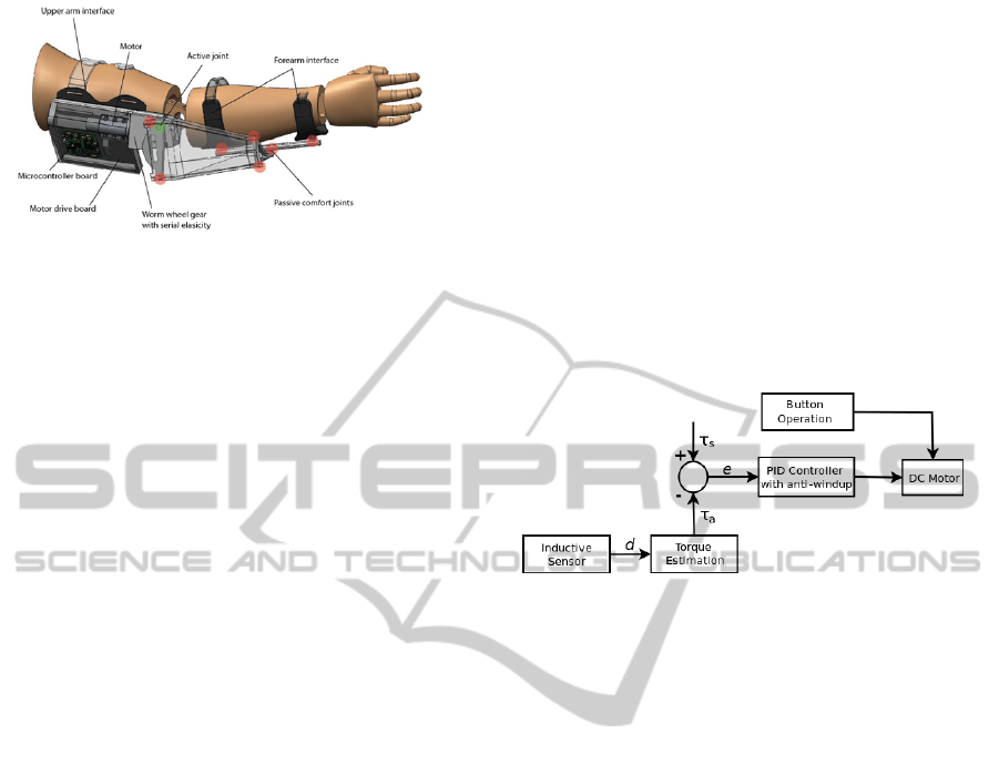
Figure 2: Mechanical design of the active Orthosis. The
red dots represent the positions of the passive degrees of
freedom.
interaction, the actuated joint is compliant. This com-
pliance is generated via serial elasticity in the worm
wheel gear set-up. The worm is axial moveable and
centred in the gear via disc springs. In case a load
is applied, the worm is pushed to one side and thus,
the spring is compressed on this side. The position of
the worm wheel is measured with a Bahluff inductive
sensor. In this way the applied load can be calculated
(see Section 4). The position of the joint is measured
with an IC-Haus-MH position encoder.
Furthermore, the used electronics consist of a
STM32F103VE microcontroller, offering several data
acquisition (GPIO) and communication (USART,
CAN-bus) ports, and a BD6232 PWM H-Bridge
driver. The current used DC-Drive can generate a
torque of about 16 Nm.
To avoid any danger for the user, various safety as-
pects are considered. Therefore, the natural working
range of the human elbow is limited by mechanical
stops. Furthermore, at too high forces the forearm in-
terface will release from the orthosis (similar to the
principle of ski binding).
The active range of motion of the elbow orthosis
corresponds to the anatomic workspace of the human
joint and is individually adjustable to each subject.
Since an additional and unilateral load can repre-
sent a major influence on, e.g., neurological patients,
the orthosis’ weight with respect to the user must be
kept as low as possible. Therefore, the orthosis’ ma-
terials is a combination of carbon reinforced plastics
and polyamid PA6, for a lightweight, robust and stiff
design. Additionally, a carrying system was devel-
oped, which distributes the weight of the device on
both shoulders.
4 CONTROL SCHEME OF THE
ORTHOSIS
Several research groups have described robotic de-
vices for upper limb rehabilitation and their strategies
to control them in a user-oriented way. In (Rosen
et al., 2001) the torque applied to the elbow joint
of an upper extremity exoskeleton is measured via a
load cell, while the set torque is calculated via mus-
cle models. In a second step, the authors derive four
performance indices, in order to calculate the magni-
tude of support by the exoskeleton from EMG data.
In (Andreasen et al., 2005) an impedance control
scheme is implemented. Two load cells in series es-
timate the joint torque which is fed into a dynamic
impedance function.
In the following the torque control system of the
proposed active orthosis will be presented. This can
be visualized in the simplified block diagram in Fig-
ure 3.
Figure 3: Block diagram of the torque control loop.
The general control structure is designed to be cas-
caded, while the main- and inner loop of the control
architecture is a torque control loop. As shown in Sec-
tion 3, the DC-drive of the device is provided with
two disc springs performing the serial elasticity of the
drive. These springs deflect when load is applied to
the joint. One is used for movements that are upwards
directed and one for movements that are downwards
directed. The inductive sensor detects this deflection
d. With these measurements it is possible to obtain a
nearly linear function between spring deflection and
the actual torque applied to the joint, τ
a
. The curve,
shown in Figure 4, was empirically determined ap-
plying several load (torque) values to the joint, and
matching this load values with the resulting spring de-
flection.
The set (desired) joint torque τ
s
at this point is fed
externally, from a computer via USART port. The dif-
ference between these two torques is the control error
e, which is propagated into an anti-windup PID con-
troller. For more information about anti-windup con-
trollers and methods, please refer to, e.g., (Bohn and
Atherton, 1995). The controller computes the voltage
for the motor needed to reach the desired torque. The
performance of the control system was verified with
weight discs in order to simulate values for τ
a
, and
giving the corresponding τ
s
to the system, resulting
in an acurate balancing of the weights. Furthermore,
the resulting measured torque was compared with the
deflection-torque curve depicted above. Figure 5 il-
AnEMG-basedAssistiveOrthosisforUpperLimbRehabilitation
325
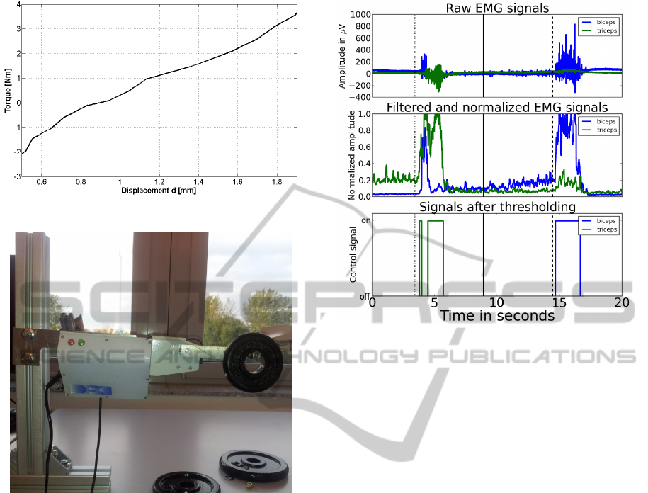
Figure 4: The calculated joint torque - deflection curve.
Figure 5: Setup for control experiments.
lustrates the experimental setup.
The torque control loop already allows to use the
upper limb orthosis in a free-running mode (with
τ
s
= 0 Nm), or in other words, to use the device as
a completely passive one.
Alternatively, the orthosis can be manually oper-
ated via two buttons at any time, supplying a con-
stant voltage of ±15 V. This allows corrections and
re-positioning of the joint if needed.
5 DETECTION OF MOVEMENT
INTENTION BY EMG
ANALYSIS
This section describes how muscle activity measured
by the EMG is used as a control signal for the active
orthosis. EMG signals are measured at two muscles
on the upper right limb (same arm at which the or-
thosis is used) named M. biceps brachii and M. tri-
ceps brachii. Ag/AgCl electrodes are used in a bipolar
Figure 6: Resulting signals after preprocessing and thresh-
olding: (top) Raw EMG signals from biceps (blue) and tri-
ceps (green), (middle) filtered and normalized signals, and
(bottom) results of the thresholding algorithm.
setup. The signals are amplified and digitalized by
a BrainExG MR (Brain Products GmbH, Germany)
amplifier and transfered to a computer with a sam-
pling frequency of 5000 Hz where they are saved or
directly processed.
The acquired signals are filtered. For this, a filter
that is based on the standard deviation (blind review
Ownpaper, 2013) is used. For this filter a sliding win-
dow of 100 ms is passed along the signal. The stan-
dard deviation of this window is assigned to the last
sample. This is done consecutively for all samples of
the streamed EMG-signals.
Afterwards the signals are normalized in a range
from 0 to 1. Often the normalization is done using the
isometric or isokinetic maximum voluntary contrac-
tions (Burden and Bartlett, 1999). Here a different
approach is used. Basically the signal is normalized
with the maximum value obtained after filtering so
far. The maximum is initialized with 1.0. If a filtered
sample has a higher value than the maximum, this
value is assigned as the new maximum. The drawback
of this method is, that big artifacts, e.g., produced
due to resistance changes at the electrode site, artifi-
cially reduce the amplitude of the normalized signals.
Therefore, a forgetting factor ε
1
with ε
1
= 0.9999 is
used to reduce the maximal value in each time step.
Further, a minimum is defined as one fourth of the
maximal value. This minimum is again degraded with
a forgetting factor ε
2
with ε
2
= 0.99999. The mini-
mum is needed to keep the normalization factor in a
BIODEVICES2013-InternationalConferenceonBiomedicalElectronicsandDevices
326

value range, where a clear distinction between base-
line noise and signal during muscle contraction can
be achieved. Without the minimum the normalization
factor could degrade to values lower than the baseline
noise values. This would lead to a value of close to 1.0
after the normalization in ranges where no movement
is performed.
The normalization needs to be calibrated, i.e.,
there has to be a contraction of each muscle to ob-
tain meaningful values from the function. The control
signals for the orthosis are obtained using a threshold
algorithm similar to the on used in (DiCicco et al.,
2004). Two thresholds are used for determining the on
and off phases of each muscle. The on threshold was
set to 0.4 and the off threshold to 0.3. This hystere-
sis is used to prevent continuous on and off switch-
ing if the normalized EMG signal has a value close
to the threshold. For the off threshold an additional
time constrain is used. The mode is only switch from
on to off, if the signal is continuously below the off
threshold for 20 ms. Further a resting time of 500 ms
in between a direction switch has to be maintained.
As a last step we had to decide which of the two mea-
sured muscles should be preferred, in case that both
were active, we decide to set both signals to 0 and
therefore to decide for none of the muscle or move-
ment directions.
With this preprocessing in combination with the
threshold algorithm, we are able to create three dif-
ferent control commands for the orthosis: (1) to flex
the arm (M. biceps brachii is active), (2) to stretch
the arm (M triceps brachii is active), and (3) to relax
(none of both muscles is active). The control signals
are derived on the computer acquiring the EMG data
and send to the orthosis via USART. All described pa-
rameters were chosen by empirical testing on EMG
data recorded with the orthosis attached to the sub-
jects arm running in free-runing-mode see Section 4.
In Figure 6 the processing of EMG data, and the
thresholding result for an arm flexion and extension
are shown. In the top, the raw EMG signals from the
biceps (blue) and triceps (green) are shown, the mid-
dle illustrates the filtered and normalized EMG sig-
nals, and finally in the bottom, the outcome from the
thresholding is shown. The three vertical lines, dot-
ted, dashed, and solid denote time points, where the
subject was asked to stretch, flex, and relax the arm re-
spectively. The stimuli for those three actions where
presented on a monitor and marked in the EMG data.
The obtained control signals can be used directly to
operate the orthosis, e.g., support the users arm move-
ment.
6 CONCLUSIONS AND
OUTLOOK
In this work we presented an active orthosis, its pos-
sible application, design and mechanics, and control.
To summarize, the system allows to support self ini-
tiated movement that are normally executed by both
upper arm muscles M. biceps brachii or M. triceps
brachii. Patients that are not able to effectively control
both muscles can be supported for individual move-
ments. This can be achieved by detecting EMG onset
activity. If EMG activity onset is detected, the or-
thosis actively executes the directed movement corre-
sponding to the active muscle.
The next developmental step is to adapt the
strength of support with respect to the strength of
muscle activity. To allow this, different methods
for EMG analysis have to be applied. These meth-
ods (Ajiboye and Weir, 2005) allow to correlate mus-
cle activity strength with the recorded signal and thus,
enable to adapt the support of the orthosis to the needs
of the patient and state of therapy.
Further, we established a collaboration with a clin-
ical partner. Supported by the medical specialists, the
design of the orthosis will be improved in order to
follow further sanitary and medical guidelines and to
define proper application scenarios. From the con-
trol side, it is important to find a way to measure the
resistance of the human-robot interaction in order to
recognize unvoluntary muscle activity due to spastic-
ity. Further, the possibility of defining torque curves
will be analysed. In specific, the development of the
applied torque by the user depending on the angular
position of the joint can be observed and defined as a
mathematical function. Using the inverse of this curve
may lead to a more natural movement.
Finally, user-friendliness elements have to be con-
sidered in the future. The possibility for therapist (and
patients) to adapt important parameters online in an
easy way, by means of some sort of intuitive user in-
terface is the goal.
ACKNOWLEDGEMENTS
This work was supported by the German Bundesmin-
isterium fur Bildung und Forschung (BMBF,grant
FKZ 01IW10001).
REFERENCES
Ajiboye, A. and Weir, R. (2005). A heuristic fuzzy logic ap-
proach to emg pattern recognition for multifunctional
AnEMG-basedAssistiveOrthosisforUpperLimbRehabilitation
327

prosthesis control. IEEE Transactions on Neural Sys-
tems and Rehabilitation Engineering, 13(3):280 –291.
Albert, S. and Kesselring, J. (2012). Neurorehabilitation of
stroke. Journal of Neurology, 259:817 – 832.
Andreasen, D. S., Allen, S., and Backus, D. (2005). Ex-
oskeleton with EMG Based Active Assistance for Re-
habilitation. In IEEE 9th International Conference on
Rehabilitation Robotics, pages 333–336.
blind review Ownpaper (2013). b.
Bohn, C. and Atherton, D. (1995). An Analysis Package
Comparing PID Anti-Windup Strategies. IEEE Con-
trol Systems, 15:34–40.
Brewer, B. R., McDowell, S. K., and Worthen-Chaudhari,
L. C. (2007). Poststroke Upper Extremity Rehabil-
itation: A Review of Robotic Systems and Clinical
Results. Topics in Stroke Rehabilitation, 14:22 – 44.
Burden, A. and Bartlett, R. (1999). Normalisation of EMG
amplitude: an evaluation and comparison of old and
new methods. Medical Engineering and Physics,
21(4):247 – 257.
Deaton, C., Froelicher, E. S., Wu, L. H., Ho, C., Shishani,
K., and Jaarsma, T. (2011). The Global Burden of
Cardiovascular Disease. Journal of Cardiovascular
Nursing, 26:5 – 14.
DiCicco, M., Lucas, L., and Matsuoka, Y. (2004). Com-
parison of Control Strategies for an EMG Controlled
Orthotic Exoskeleton for the Hand. In Proceedings of
the 2004 IEEE International Conference on Robotics
and Automation (ICRA ’04).
Gomez-Rodriguez, M., Grosse-Wentrup, M., Hill, J.,
Sch
¨
olkopf, B., Gharabaghi, A., and Peters, J. (2011).
Towards Brain-Robot Interfaces for Stroke Rehabilita-
tion. In Proceedings of the International Conference
on Rehabilitation Robotics (ICORR). Intelligent Au-
tonomous Systems.
Henze, T. (2007). Moderne Rehabilitation nach Schlagan-
fall. NeuroTransmitter, pages 59–67.
Johnston, M. (2009). Plasticity in the Developing Brain:
Implications For Rehabilitation. Developmental Dis-
abilities Research Reviews, 15:94 – 101.
Loureiro, R. C. V., Harwin, W. S., Nagai, K., and Johnson,
M. (2011). Advances in upper limb stroke rehabilita-
tion: a technology push. Medical & Biological Engi-
neering & Computing, 49:1103 – 1118.
Platz, T. and Roschka, S. (2009). Rehabilitative Therapie
bei Armparese nach Schlaganfall. Neurol Rehabil,
pages 81–106.
Rosen, J., Brand, M., Fuchs, M., and Arcan, M. (2001).
A Myosignal-Based Powered Exoskeleton System. In
IEEE Transactions on Sytems, Man, and Cybernetics -
Part A: Systems and Humans, volume 31, pages 210–
222.
Schmitz, B., Wiegand, R., Pylatiuk, C., Rupp, R., and
Schulz, S. (2011). Erste Erfahrungen mit dem Ortho-
Jacket. Orthop
¨
adie-Technik, 4:256 – 261.
BIODEVICES2013-InternationalConferenceonBiomedicalElectronicsandDevices
328
