
Model Driven Engineering of Cross-layer Monitoring and Adaptation
Hui Song
1
, Amit Raj
1
, Saeed Hajebi
1
, Siobh
´
an Clarke
1
and Aidan Clarke
2
1
Lero: The Irish Software Engineering Research Centre,
School of Computer Science and Statistics, Trinity College Dublin, Dublin 2, Ireland
2
IBM Software Ireland Lab., Dublin, Ireland
Keywords:
Multilayer Systems, Monitoring, Dynamic Adaptation, Model Driven Engineering, Bidirectional Model
Transformation.
Abstract:
Monitoring and adaptation of multilayer systems are challenging, because the mismatches and adaptations are
interrelated across the layers. This interrelation introduces two important but difficult questions. 1) When
a system change causes mismatches in one layer, how to identify all the cascaded mismatches on the other
layers? 2) When an adaptation is performed at one layer, how to find out all the complementary adaptations
required in other layers. This paper presents a model-driven engineering approach towards cross-layer moni-
toring and adaption of multilayer systems. We provide standard meta-modeling languages for system experts
to specify the concepts and constraints separately for each layer, as well as the relations among the concepts
from different layers. An automated engine uses these meta-level specifications to 1) represent the system
states on each layer as a runtime model, 2) evaluate the constraints to detect mismatches and assist adaptations
within a layer, and 3) synchronize the models to identify cascaded mismatches and complementary adaptations
across the layers. We illustrate the approach on a simulated crisis management system, and are using it on a
number of ongoing projects.
1 INTRODUCTION
Recent technological advancements have allowed
large-scale systems to organize themselves into dif-
ferent layers. For example, a service oriented sys-
tem is often considered to be constituted of the busi-
ness layer, the service layer, and the infrastructure
layer(Kazhamiakin et al., 2010). Embedded systems
span three typical layers of the application, the oper-
ating system, and the device (Yuan et al., 2006).
Although the multilayer style separates the con-
cerns of system development, the runtime monitoring
and adaptation on different layers are still interrelated
with each other. In particular, a mismatch (a situation
which is not in accordance with the desired one) hap-
pened in one layer may influence other layers, and an
adaptation on one layer may require complementary
adaptions on the other layers. This causes two ques-
tions: 1) When a mismatch is captured from one layer,
how to find out the related mismatches from other lay-
ers before they would have actually showed their im-
pact. 2) When an adaption is performed on one layer,
how to identify all the complementary adaptions on
other layers before executing them on the system.
A typical idea towards cross layer system adapta-
tion (Yuan et al., 2006; Zengin et al., 2011; Guinea
et al., 2011; Popescu et al., 2012) is to regard the sep-
arated layers as a whole again, by explicitly defining
the relations between the mismatches and solutions
from different layers, and employ a centralized mech-
anism to handle them. These approaches actually vi-
olate a basic principle of multilayer systems, i.e., the
separation of concerns between layers. In particular,
following these centralized approaches, the one who
performs adaptations or defines adaptation templates
has to consider all the mismatches and modifications
from all layers, as well as the complex relations be-
tween them. Moreover, the technical binding between
layers can be flexible, and the mismatch and adap-
tation on different technologies vary. This makes it
harder to enumerate all the possible adaptations and
their relations in advance. In summary, such central-
ized approach towards cross layer adaptation is not a
good way towards the “software engineering of sys-
tem adaption” (Cheng et al., 2009).
In software development, Model-Driven Engi-
neering (MDE) (France and Rumpe, 2007) is one of
the promising approaches to coping with the corre-
lation between different development steps. The in-
formation about the system in different steps is cap-
331
Song H., Raj A., Hajebi S., Clarke S. and Clarke A..
Model Driven Engineering of Cross-Layer Monitoring and Adaptation.
DOI: 10.5220/0004375203310340
In Proceedings of the 1st International Conference on Model-Driven Engineering and Software Development (MODA-2013), pages 331-340
ISBN: 978-989-8565-42-6
Copyright
c
2013 SCITEPRESS (Science and Technology Publications, Lda.)

tured by different models. Developers focusing on a
particular step only work on the model of that step,
and the effect is automatically propagated to the other
layers via model transformation. For example, in
the Model-Driven Architecture approach, designers
work on the platform-independent model (PIM) with-
out caring about the platform details, and their design
decisions will be embedded in the platform-specific
model (PSM) via the model transformation from PIM
to PSM.
In this paper, we present an MDE approach to-
wards cross-layer system monitoring and adaptation
in a decentralized manner. The key information and
the runtime status in each layer is captured by a run-
time model (Blair et al., 2009), which is aligned to the
concerns and techniques in that layer. Monitoring and
adaptation are performed within each layer based on
its model, and their effects to the other layers will be
automatically propagated to the layers via transforma-
tion between models. At design time, the mismatch
and solution specifications are defined on the layer-
specific models, and it is not required to enumerate all
the potential relations between adaptations from dif-
ferent layers in advance. At runtime, the adaptation
agents work separately in their own layers
1
. Using
their own models, they can see the influence of mis-
matches or modifications happened on the other lay-
ers, propagate their adaptation results to the other lay-
ers to ask for complementary adaptations, and check
the effect of their adaptation through the feedback
from other layers. The challenge here is that the
different layers of a system are changing and being
modified simultaneously, and in each layer’s model,
the information particular to this layer and the infor-
mation influenced by other ones are mixed together.
This requires more sophisticated model synchroniza-
tion solution, rather than the simple, unidirectional,
and once-for-all model transformation.
Our contributions can be summarized as follows.
1. We propose a language stack towards the mod-
eling of multilayer systems and the cross layer
adaptation on them, based on OMG’s MOF meta-
modeling standards.
2. We utilize the OCL evaluation for the detection of
mismatches, and the bidirectional transformation
to spread the changes and modifications across
layers.
3. We design the algorithms to integrate the check-
ing, fixing, and transformation techniques to-
1
This work is focused on the adaptation assistance, and
thus we assume that in each layer, there is an external adap-
tation agent which plans the proper adaptation based on the
mismatches. How these agents work is out of the scope of
this paper.
gether to detect cascaded mismatches and com-
plementary adaptions across layers.
We illustrate the approach on a simulated three-
layered, service-based Crisis Management System,
and also illustrate its feasibility by introducing our on-
going projects.
The rest of the paper is organized as follows. We
introduce the approach and a motivating example in
Section 2. We present the design and runtime as-
pects in Section 3 and 4, and evaluate the approach
on the motivating example, as well as other ongoing
projects in Section 5. Section 6 discusses the related
approaches and Section 7 concludes the paper.
2 THE APPROACH
2.1 Motivating Example
We take a crisis-management system (CMS) (Popescu
et al., 2012) as a sample multilayer system through-
out this paper. When a flood incident is reported, an
emergency centre performs rescue operations by or-
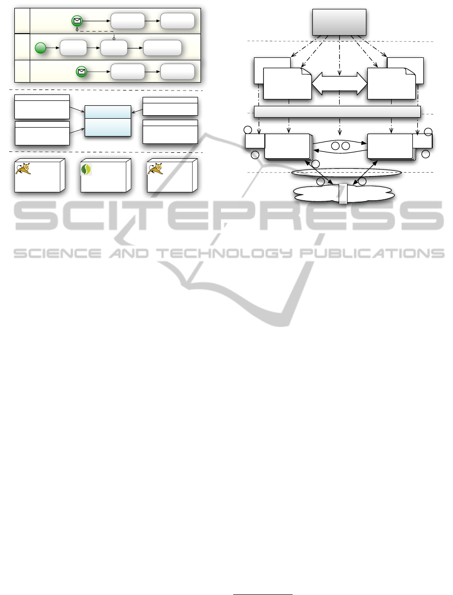
ganizing other departments to work together. Figure 1
illustrate the three layers of this CMS: 1) In the Busi-
ness Process Management Layer (BL), the simplified
workflow of the emergency centre is constituted by
three activities, i.e., get location, launch rescue, and
file the incident record. The rescue activity is dele-
gated to medical service which sends ambulance to
the indicated location. The army service with heli-
copter is a backup. 2) In the Service Layer (SL), the
activities and processes are implemented or defined as
services. One service could be registered to another
one so that the latter could utilize the former’s func-
tions. 3) In the infrastructure layer (IL), the services
are hosted by different server nodes.
The mismatches and adaptations usually happen
in a particular layer, but may influence the other
layers. For example, the crash of the Tomcat1
server (a mismatch in the IL), causes the GetGPS and
MedicalService not available (SL), which eventu-
ally results in the brokerage of the workflow in the
emergency centre (BL). For another example, if the
governor from the business layer observes that the
flood has damaged the roads, and thus the medical
service’s ambulance is of no use, then he/she adapts
the business process to delegate the Rescue activity to
the Army service (BL). This adaptation alone is not
enough: We first need to register the ArmyService
to the EmergencyCentre (SL). After that, since the
Army service requires GSNLocation as input, which
does not match the output of GetGPS service, an
MODELSWARD2013-InternationalConferenceonModel-DrivenEngineeringandSoftwareDevelopment
332
Medical
Service
Emergenc
yCentre
Get
GPS
Rescue
File
Incident
Send
Ambulance
GetGPS
MedicalService
EmergencyCentre
FileURL
Tomcat1
Spring
Record
Rescue
EmergencyCentre
Army
Servic
e
Send
Helicopter
Record
Rescue
ArmyService
GetGSN
ArmyControl
Tomcat2
in:LocationReques
out:GPSLocation
impl:GetGPSClass
GetGPS
in:GPSLocation
out:RescueRecord
impl:MedicalURL
MedicalService
in:IncidentRecord
impl:FileClass
FileIncident
In: GSNLocation
out:IncidentRecord
impl:ArmyURL
ArmyService
Business Process
Services
Infrastructure
Figure 1: Part of the crisis management system (CMS).
adapter (say GPStoGSN) is required between GetGPS
and Rescue (BL) . It then requires the implementation
of the corresponding service (SL), and the deploy-
ment of it to the node of Tomcat2 (IL). If this node is
overloaded, the infrastructure administrator will have
to migrate the service to the Tomcat1.
These scenarios reveal the interrelation of mis-
matches and adaptations across the layers, and in this
paper, we answer the two questions caused by this in-
terrelation: 1) When a change happened on one layer,
how to identify all the related mismatches from all the
layers, before the effect of this change is observable
on other layers? and 2) If an adaptation is performed
on one layer, how to predict all the required comple-
mentary adaptations on all the layers, before actually
executing the adaptation to the system.
Regarding these problems, a direct solution is to
do adaptation from a global perspective. To do this,
we should either specify the mismatch or solutions on
the concepts from different layers, or specify them on
separate layers, but in the same time explicitly provide
the relations between them across the layers. How-
ever, as we have argued in Section 1, this requires
strong expertise from the users who perform adapta-
tion or provide the adaptation specifications. Alterna-
tively, in this paper, we choose a decentralized way:
Users perform or specify the adaptation in the sepa-
rate layers, and our approach automatically derive the
global adaptation from the separate ones.
2.2 The Approach Architecture
We provide an MDE approach to cross-layer sys-
tem monitoring and adaptation. At design time, we
constraintconstraint
Modeling
Languages
Layer1
MetaModel
Layer2
MetaModel
conceptual
relation
Layer1
model
Layer2
model
m/a
m/a
runtime model
engine
M3
M2
M1
M0
1
2
3
3
5
5
5
4
6
Model-Driven Adaptation Engine
Figure 2: Approach architecture.
provide the languages for system experts to define
the concepts of each layer and the relation between
them across layers, and also to define the mismatches
and possible solutions on individual layers. At run-
time, we provide an engine that captures the system
changes, identify the mismatches on all the layers
caused by the changes, and predict the complemen-
tary adaptations on different layers when an admin-
istrator performs an adaptation on a particular layer.
Figure 2 illustrates the approach architecture, accord-
ing to the four-level meta-modeling architecture de-
fined by OMG
2
.
In the M3, or meta meta level, we provide the
meta-modeling languages, which are used in the M2,
or meta level, by system experts to define the system
and its layers. Specifically, the system experts define
the concepts in a layer as a meta-model, and define
the mismatches and their solutions as constraints on
the meta-model. Between the layers, the experts use
the meta-model relations to define the relations be-
tween the concepts from different layers. These three
specifications are defined using the OMG standard
languages, MOF, OCL, and QVT-Relational, respec-
tively
3
. We describe how to use these languages, and
their semantics on adaptation in Section 3.
M1 and M0 shows how the approach works at
runtime. A typical process is as follows: A system
change on layer1 is captured by the runtime model
(marked as step 1). The engine synchronizes the two
models using bidirectional model transformation to
propagate the changes (2), and then evaluate the con-
2
http://www.omg.org/mof/
3
http://www.omg.org/spec/index.htm
ModelDrivenEngineeringofCross-LayerMonitoringandAdaptation
333

ILSLBL
name:String
Lane
name:String
start:Boolean
msg:Boolean
Activity
name:String
invalid:Boolean
Connection
activity*
from*
to*
name:String
in:Type
out:Type
impl:URI
Service
registeredTo
name:String
type:Server
Node
name:String
Component
hosted*
Figure 3: Simplified meta-models.
straints on both models and return the detected mis-
matches on each layer to the corresponding admin-
istrators (3). If an adaptation is applied on layer2
(4), the engine propagates the modification to layer1
(5), check mismatches and suggest complementary
adaptations on layer1 (6). When all the mismatches
are resolved, the final modifications on both runtime
models are executed to the system. In Section 4, we
present how the evaluation and bidirectional transfor-
mation approaches work, and how we use them to-
gether as an integrated adaptation process.
3 SYSTEM MODELING
3.1 Layer Meta-models
A meta-model defines the system concepts for a par-
ticular layer, the properties of each concept, and the
association between the concepts inside the layer. The
meta-model is specific to the technique and knowl-
edge base in the layer. Figure 3 shows the simplified
meta-models for our running example. It is worth to
notice that a typical system with well-accepted layers
does not require its meta-models to be defined from
scratch, but using the meta-models according to the
existing languages or APIs in the layers (Song et al.,
2010). For example, the meta-model in the business
layer is simplified from BPMN.
3.2 Relations
For two layers’ meta-models M
i
and M
j
, there ex-
ists a relation R
i j
⊆ M
i
× M
j
. If the two layer mod-
els m
i
∈ M and m
j
∈ M
j
satisfies (m
i
, m
j
) ∈ R
i j
, we
say the two models are consistent, simply notated as
R
i j
(m
i
, m
j
). QVT-Relational, or simply QVT-R, is a
declarative model transformation language designed
on the basis of relation theory, and thus we use it as
a language in our approach to specify the relation be-
tween the concepts from different layers. It is worth
noting that the relations defined by QVT-R can be
sophisticated, rather than simply one-to-one mapping
between model elements. Similar to the meta-models,
the specification of relations could also benefit from
existing research on the transformation between dif-
ferent layers (Raj et al., 2008).
Figure 4 illustrates the QVT relations we defined
between business layer and service layer. The two
relations on the lefthand side explains that a service
in SL is related to a lane, or a non-message, non-
start activity with the same name in BL. The mid-
dle part defines the relations between delegations (a
special type of connections) and the registrations be-
tween services: If there is a delegation c connects two
services a1 and a2, and their parents are l1 and l2,
then there must exist two services s1 and s2 corre-
sponding to the two lanes (according to the relation
defined before), and s1 is registeredTo s2. The
righthand side part defines a criteria for a connection
to be exist: If there is a connection between a1 and
a2, a1 maps to service s1, a2 (or the lane of its dele-
gated service l) maps to s2, then s1 and s2 must be
matched on their input and output. It is worth noting
that though we introduce the relations in a direction
from BL to SL, they actually do not have a direction.
We can understand and execute it in either directions.
3.3 Constraints
The constraints on a meta-model defines the desired
model instances under this meta-model. A mismatch
appears when the system state does not satisfy the
constraints. Following the OMG’s meta-modeling
standards, we utilize the OCL language for the speci-
fication of constraints.
The simplest form of constraint on a meta-model
is a predicate on the set of model states under the
meta-model, which defines what model state is ac-
ceptable. However, many constraints do not only de-
pend on he current model state, but also the original
state before the change. Taking the typical “missing
role” mismatch as an example (Popescu et al., 2012).
When we say we miss a role, we actually mean there
was a role, but now, due to the system change, this
role no longer exists. Such a constraint is a predi-
cate on the model change, or an imply connecting two
predicates on the two model states before and after the
change, respectively.
Figure 5 shows two sample constraints that we de-
fined for service layer and infrastructure layer. The
first constraint describes that a registered service can-
not be missed after the change. We use a pair of OCL
pre and post to say that if there was a service that reg-
istered to another one, then this service cannot disap-
pear after the change. The second constraint is state-
based. We use OCL inv to describe that a server’s
hosted components cannot exceed 4. Along with the
MODELSWARD2013-InternationalConferenceonModel-DrivenEngineeringandSoftwareDevelopment
334

Activity2Service(a1,s1);
Activity2Serive(a2,s2) or Lane2Service(l,s2)
s1.out <> s2.in
when
Connection2Services
Activity2Service
《domain》
name=an
msg=false
a:Activity
《domain》
name=an
s:Service
service
bpm
Lane2Service(l1,s1)
Lane2Service(l2,s2)
when
Delegation2Registration
《domain》
delegation=true
c:Connection
《domain》
s1:Service
service
bpm
s2:Service
registeredTo
a1:Activity
start=true
a2:Activity
l1:Lane l2:Lane
from
to
parent
Lane2Service
《domain》
name=an
l:Lane
《domain》
name=an
s:Service
service
bpm
《domain》
delegation=false
invalid=true
c:Connection
《domain》
s1:Service
service
bpm
a1:Activity a2:Activity
from
to
《domain》
s2:Service
delegation=true
d:Connection
a3:Activity l:Lane
Figure 4: Sample QVT relations.
1constraint:
2 mismatch ’Registered service is missed’
3 predicate context Service
4 pre: not self.registered.oclUndefined()
5 post: not self.oclUndefined()
6constraint:
7 mismatch ’Server overloaded’
8 predicate context Node
9 inv self.hosted−>size()<4
10 fixing let alt=self.parent.node
11 −>select(e|e.type=self.type
12 and e.hosted−>size<4)
13 −>getFirst().hosted
14 −>add(self.hosted−>getLast())
Figure 5: Sample constraints.
constraint, we also defined an automated fixing logic,
to find another node with the same type, and transfer
one component to that node.
4 CROSS-LAYER ADAPTATION
In this section, we first introduce the techniques we
utilize to maintain the runtime models, synchronize
them across layers, and do monitoring and adaptation
within a layer. After that, we present the algorithm to
integrate these techniques together to achieve a semi-
automated cross layer adaptation approach.
4.1 Supporting Techniques
Runtime Models. For each layer, we maintain a
model instance conforming to the defined meta-
model. As a runtime model, there exists a causal
connection between the model and the system (Blair
et al., 2009). That means a system change will cause a
model change immediately, and a model modification
will influence the system, as well. There exists many
different techniques to maintain the causal connec-
tion, such as API wrapping (Sicard et al., 2008; Song
et al., 2009) and event correlation (Schmerl et al.,
2006). Based on the causal connections, when the
system or the context evolves on a layer, we get two
model states m and m
0
reflecting the system state be-
fore and after the change. The resulted modification
of an adaptation is captured by a new model state m
00
,
and the causal connection will automatically update
the system state to be consistent with this new model
state.
Bidirectional Model Transformation. A QVT
bidirectional transformation is constituted by two
functions derived from the relation between two meta-
models (Stevens, 2007):
−→
R : M × N → N;
←−
R : M ×
N → M. The first function
−→
R (m, n) = n
0
takes two
model state m and n as input, and returns a new
state n
0
, satisfying (m, n
0
) ∈ R. The second function
←−
R (m, n) = m
0
does the same thing but in the oppo-
site direction. The two functions satisfy three prop-
erties, namely the correctness, harmlessness, and un-
doability (Stevens, 2007). Each transformation does
not construct a target model from scratch, but uses
the current target model state as a reference, change
it to satisfy the relation, and keep the irrelevant part
unchanged.
We use bidirectional transformation to propagate
changes between layers. For two layers reflected
by their models in state m
i
and m
j
respectively, if
a change is captured by m
0
i
, then the transformation
result m
0
j
=
−→
R
i j
(m
0
i
, m
j
) contains the influence of this
change on the other layer. Similarly, if an adaptation
modifies the target layer model from m
0
j
to m
00
j
, the re-
sult of the other transformation m
00
j
=
←−
R
i j
(m
0
i
, m
00
j
) de-
scribes how this modification effect the original layer.
We use the sample relations in Figure 4 to show
how bi-transformation works. Suppose an administra-
tor modifies the business layer model in Figure 1, and
redirects the delegation of Rescue to ArmyService.
ModelDrivenEngineeringofCross-LayerMonitoringandAdaptation
335

If we execute the transformation according to relation
delegation2Registration, using the new business
layer model and the current service layer model as in-
puts, we will find l1 and l2 as EmergencyCentre
and ArmyService, and thus s1 and s2 will be the
services with the same names, and we construct a
new registeredTo between them. For another ex-
ample, after this change, when executing the rela-
tion Connection2Service from SL to BL, we will
find a pair of s1 and s2 as EmergencyCentre and
ArmyService, and the corresponding a1 and l as the
activity and lane with the same name. Since s1.out
does not equal to s2.in, c.invalid will be set to
true. After these two transformations, we automati-
cally find out a new BL mismatch caused by the adap-
tation, with the help of SL information.
Adaptation within a Layer. We use the constraints
defined in Section 3 to do monitoring and modifica-
tion within one layer. In case of monitoring, the two
model states m and m
0
before and after the change
are used as the input to evaluate each constraint’s
predicate. For a state-based predicate SP, we eval-
uate if m
0
|= SP, and for a change-based predicate
CP = (pre, post), we check if m |= pre → m
0
|= post.
If the evaluation fails, we collect the mismatch de-
scription, and the model elements that breaks the con-
straint. After collecting the mismatches, we perform
both automated and manual adaptations to fix them.
When a mismatch has a fixing logic defined as an
OCL expression, we evaluate the expression on the
new model state m
0
, and return the result m
◦
as the
new adaptation result. Otherwise we leave the mis-
match for human administrators to handle. In the
practical situation, it is possible that some mismatches
are not possible to completely resolve instantly, and
administrators may have to tolerate it to keep the sys-
tem serving. To support this flexibility, we also allow
administrators to ignore a mismatch, and regard this
as a special kind of adaptation.
4.2 The Integrated Algorithm
We integrate the above techniques into the cross layer
monitoring and adaptation algorithm. In a system
with k layers, monitoring returns k mismatch sets,
each of which contains the mismatches detected in a
particular layer. On the contrast, adaptation is a pro-
cess to eliminate these mismatches: We first try to re-
solve the mismatches according to their fixing logics,
and then provide the rest of the mismatches to the ad-
ministrators, so that they can use the new mismatches
as a reference to make manual adaptation decisions,
either to modify the model or ignore the mismatch.
After each adaptation, we synchronize the modified
model state to the other layer models, evaluate the
constraints, and update the mismatch sets.
Algorithm 1: Cross-layer monitoring and Adapta-
tion.
Ref: M = {M
i
}, C = {C
i
}, 1 ≤ i ≤ k: The
meta-models and constraints of the k layers.
R = {R
i j
}, 1 ≤ i ≤ k − 1, j = i + 1: The
relations between neighboring layers.
In: {δ
i
= (m
i
, m
0
i
)},: The changes on the k models
Out: {m
◦
i
}: The model states after the adaptation
Inter: {Msm
i
}: The set of mismatches. Ign: The
mismatches ignored by administrators
Monitoring:
queue ← {i|1 ≤ i ≤ k}1
while queue 6= {} do2
i←queue3
foreach j ∈ {i − 1, i + 1} ∩ {1, ..., k} do4
m←
−→
R
i j
(m
0
i
, m
0
j
)
5
if m 6= m
0
j
then m
0
j
←m, queue← j
6
foreach i do Msm
i
←Eva[[C
i
]](m
i
, m
0
i
)7
Adaptation:
while (Unhd≡
S
i
Msm
i
− Ign) 6= {} do8
while (∃msm ∈ Unhd)[msm. f ix 6= φ] do9
msm≡(i, c, e ⊆ m
0
i
)10
m
◦
i
←Fix[[c]](msm, e, m
0
i
)11
Spread (i, m
0
i
, m
◦
i
)12
(m
◦
i
, Ign
i
)←ManualAdaptation()13
Ign←Ign ∪ Ign
i
14
Spread (i, m
0
i
, m
◦
i
)15
Procedure Spread (i, m
0
i
, m
◦
i
) begin16
Msm
i
←Eva[[C
i
]](m
i
, m
◦
i
)17
for j ∈ {i − 1, i + 1} ∩ {1, ..., k} do18
m←
−→
R
i j
(m
0
i
, m
◦
j
)
19
if m 6= m
◦
j
then
20
m
◦
j
←m
21
Msm
j
←Eva[[C
j
]](m
j
, m
◦
j
)
22
end23
Algorithm 1 illustrates our monitoring and adap-
tation algorithms. Using the meta-level specifications
as references, the input is a set of k changes δ
i
cap-
tured on the layer runtime models, and the output is
k sets of mismatches Msm
i
(for monitoring) and the
new model states m
◦
i
(for adaptation) representing the
modifications to the systems on different layers.
Monitoring is implemented as a breadth-first
search. We use a queue to store the layers that is not
stable yet, and this queue is initialized with all the
MODELSWARD2013-InternationalConferenceonModel-DrivenEngineeringandSoftwareDevelopment
336

layers first (Line 1). Until the queue becomes empty,
we keep on executing a loop to spread the changes.
In each iteration, we take one layer i out from the
queue, synchronize the current state m
0
i
at layer to
its two neighbors. If the transformation result m is
not the same as the input m
0
j
, then it means that the
layer j is not stable yet, and we put it into the queue.
Thanks to the Harmlessness property of bidirectional
transformation, if a layer model already embeds the
modifications from another layer, the transformation
will keep the model state unchanged. In this way, the
spread process will not fall into an endless loop, and
we will finally reach a stable set of model states. After
that, we evaluate the constraints on each model, and
find the violated ones to fill the mismatch set.
Adaptation is implemented as a semi-automated
loop, which ends until the mismatch sets from all the
layers are empty, or all the left mismatches are marked
as ignored by administrators (Line 8).
Inside the main loop, we first try to resolve the
mismatches that have fixing logic (Lines 9-12). For
such a mismatch, we execute its fixing logic and get
a new model state m
◦
i
(Line 11), and spread this new
modification to the neighboring layers (Line 16-22).
Inside the spread procedure, we first re-evaluate the
constraint, in order to delete the resolved mismatches
and see if new ones are introduced (Line 17). After
that, we use bidirectional transformation to synchro-
nize the modification result m
◦
i
with the newest state
of the neighboring model m
◦
j
(Line 19). If the result is
different, then it means that the modification on layer
i has influence on layer j. Thus we re-evaluate the
constraints on j, and update Msm
j
. In this way, we
will remove the mismatches that are resolved by the
modification on another layer, and also record the new
mismatches on the remote modification.
When a set of mismatches are resolved automati-
cally, we provide the remaining mismatches to the ad-
ministrators. The invocation to ManualAdaptation
on Line 13 will be blocked until any administrator on
any layer perform a modification. The process will
continue with the modified model state captured by
m
◦
i
, and the mismatches ignored by the administra-
tor recorded in Ign
i
. After that, we will do the same
spread approach as for the automated adaptation.
After an adaptation (automated or manual), the
subsequent spread procedure presents effects as fol-
lows. 1) If two mismatches from two layers i and j
describes the same system fault, then the transforma-
tion of the adaptation result on i will no long cause the
original mismatches on j, and thus the mismatches
caused by the same source do not need to be resolved
twice. 2) If the adaptation on one layer i requires
the complementary modifications on other one j, the
evaluation on the transformation result m
o
j
will add
new mismatches to the mismatch set Msm
j
to indicate
the required complement modification. If a new mis-
match has a fix logic, the required modification will
be automatically performed, otherwise, the mismatch
will be a hint for further manual adaptation to com-
plete the modification. 3) If an adaptation on one layer
i is illegal because its complementary modification on
another layer j (say msm
j
) cannot be resolved, then
the administrator will have to ignore j, without any
modification. In this situation, the backward transfor-
mation from j to i will roll the model state back on i,
and throw the original mismatch again. This tells the
administrator on layer i that his adaptation has failed.
The Undoability property of bidirectional transforma-
tion (Stevens, 2007) guarantees that such unsuccess-
ful adaptation can be clearly rolled back.
5 EVALUATION
5.1 The CMS Case Study
We implemented the approach on a simulated crisis
management system. The simulation had the similar
function and structure as described by Popescu et al.
(Popescu et al., 2012). For the sake of simplicity, we
implemented it based on the Spring platform
4
. In the
Business Layer, the processes were specified and ex-
ecuted based on Apache Camel
5
. The activities and
lanes mapped to the end points and routes in Camel,
and the delegation was defined as the reference from
an end point to another route. In the Service Layer,
we implement the services as Java Beans, Servlets,
or by the workflows defined by Camel (the services
that maps to lanes). The services were specified in
the Spring configuration files, which also embedded
the registration relation. Finally, in the Infrastructure
layer, the Beans and Servlets were running Tomcat
servers.
We implemented the approach based on the
Eclipse Modeling Framework (EMF
6
). We repre-
sented the information from each layer as an EMF
model, and implemented a simple runtime model en-
gine to maintain the causal connection: For the higher
two layers, the engine translates XML configuration
files to EMF model, and vice versa, and for the infras-
tructure layer, the engine retrieves and updates system
state via server APIs and configuration files. Based
on the EMF runtime model, we implemented the con-
4
http://www.springsource.org
5
http://camel.apache.org
6
http://www.eclipse.org/modeling/emf/
ModelDrivenEngineeringofCross-LayerMonitoringandAdaptation
337
Medical
Service
Emerge
ncyCent
re
Rescue
Send
Ambulance
Army
Service
Send
Helicopter
Get
GPS
Medical
Service
Emerge
ncyCent
re
Rescue
Send
Ambulance
Army
Service
Send
Helicopter
Get
GPS
EmergencyCentre
in:GPSLocation
out:Rescue...
impl:Medical...
MedicalService
In: GSNLocation
out:Incident…
impl:ArmyURL
ArmyService
EmergencyCentre
Medical
Service
Emerge
ncyCent
re
Rescue
Send
Ambulance
Army
Service
Send
Helicopter
Get
GPS
Medic
alServ
ice
Emerg
encyCe
ntre
Resc
ue
Send
Ambulance
Army
Service
Send
Helicopter
Get
GPS
GPS
GSN
In: GPSLocation
out:GSNLocation
impl:null
GPSGSN
EmergencyCentre
In: GPSLocation
out:GSNLocation
impl:GPSGSNSev
GPSGSN
EmergencyCentre
GetGPS
MedicalService
Tomcat1
ArmyService
GetGSN
ArmyControl
Tomca
t2
GetGPS
MedicalService
Tomcat1
ArmyService
GetGSN
ArmyControl
GPSGSN
Tomca
t2
GetGPS
MedicalService
GPSGSN
Tomcat1
ArmyService
GetGSN
ArmyControl
Tomca
t2
1
2
3
4
5
6
7
8
x
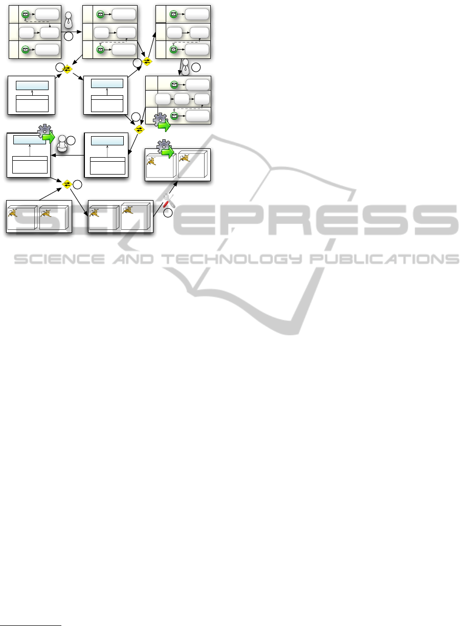
Figure 6: Adaptation scenario.
straint evaluation and bidirectional model transfor-
mation using the Eclipse OCL engine and the me-
diniQVT
7
transformation engine, respectively.
We describe two typical scenarios as follows:
The first scenario simulates how to get the mis-
matches on all the layers caused by the crash of a
node in IL. We stopped the Tomcat node, and this
change was captured by the IL runtime model with
the disappear of the first Node. The relation between
IL and SL was defined that the components maps to
the services with the same names, and thus the trans-
formation from IL to SL resulted in the disappearing
of GetGPS and MedicalService. The subsequent
transformation from SL to BL, according to the re-
lations defined in Figure 4, caused one activity and
one lane to get disappeared. After the synchroniza-
tion, the evaluation of the SL model according to the
constraints as defined in Figure 5 yields two “missing
registered services” mismatches. The evaluation on
the BL model yields the missing activities and miss-
ing delegation targets mismatches. These mismatches
are returned to different system administrators.
The second scenario shows how the approach as-
sists system administrators in adapting the system, as
illustrated in Figure 6. Following the description in
Section 2.1, the adaption started from a BL adminis-
trator who redirects Rescu to ArmyService (marked
as 1 in the figure). The first transformation yields
a new SL model with a new registration link, and
since this model was changed, the adaptation engine
7
http://projects.ikv.de/qvt
went on to spread it, and the backward transforma-
tion from SL to BL changed a connection to invalid
(step 3, as shown in Section 4), because the two ser-
vices are not compatible. This new mismatch led the
BL administrator to add an adapter between GetGPS
and Rescue (4), and the transformation adds a new
service in SL model, and automatically generate its
input and output types (step 5), but leave impl as
empty. The mismatch of “service not implemented”
calls for SL maintainers to implement the service (6).
The default transformation (7) deploy the new ser-
vice to Tomcat1, but the fixing logic of the constraints
shown in Figure 5 automatically migrates the compo-
nent to the other server for balance (8). Finally, no
transformation would cause new changes on the mod-
els, and we execute the final models of the three layers
(marked by gears in the figure) back to the system.
The scenarios reveal the following features of our
approach. 1) Separation of concerns. At design time,
the mismatches are specified on the concepts within
a particular layer, and no explicit links need to be de-
fined between mismatches from different layers. At
runtime, administrators handle mismatches and do
adaptations on their own layers. 2) Automation. The
spread of mismatches and adaptations are automati-
cally performed by the engine. We also support the
automated adaptation to resolve some mismatches,
provided that the fixing logics are defined. 3) Produc-
tivity. The inputs required by this approach are high-
level meta-models, constraints, and relations, in stan-
dard modeling languages. Users do not need write
any low-level code. The specifications are reusable
between systems with similar layers.
5.2 Ongoing Projects
We are also using the approach to support other case
studies on different systems.
Smart Office. We have a smart office system which
uses sensors to capture the physical environment of
the office rooms, and the RFID devices to trace the
location of office members and key assets. The key
function of the system is to automatically detecting
the mismatches among the members, assets and envi-
ronment, e.g., a member forgets his personal belong-
ing in a meeting room, or forget to turn off the heat-
ing system, etc. Following the approach in this pa-
per, we divide the system into the cyber and physical
layers. The former captures the device information,
and is organized using the low-level concepts such as
RFID reader, temperature sensor, etc. The latter de-
scribes the office in the concepts such as members,
rooms, things. We use bidirectional transformation to
MODELSWARD2013-InternationalConferenceonModel-DrivenEngineeringandSoftwareDevelopment
338

synchronize the two layers, so that the office adminis-
trator can define the mismatches purely in the physi-
cal layers, and the execution of these mismatches will
utilize the cyber information.
Cloud Infrastructure. We are now working to-
gether with a telecom company on a project for the
optimization of urban scale cloud infrastructure. We
regard the cloud infrastructure as a three-layer sys-
tem, including the topology of servers and switchers,
the geographical layout of these nodes, and the con-
ceptual relation between applications and the cloud.
Based on the idea of model-driven engineering, we
reify each layer as a separate model, and synchronize
these models to support the cross-layer optimization,
such as reorganizing the topology of servers with the
consideration of geographical layout between servers.
6 RELATED WORK
Existing approaches on cross-layer adaptation often
follow a centralized way. Guinea et al.’s framework
(Guinea et al., 2011) allows different techniques to
monitor different layers, but employs a centralized
adaptation agent to collect the events and analyze the
violation of key performance indicators. Popescu et
al. (Popescu et al., 2012) execute adaptations follow-
ing a set of predefined templates, and in these tem-
plates, users have to explicitly define for each adap-
tation solution, what mismatches would be raised on
other layers. In contrast, we adopt a decentralized
approach, where mismatches and adaptations are de-
fined and performed separately on different layers,
and we automatically calculate the dependency using
the relation between layer concepts. From this per-
spective, our approach is related to ECMAF (Zegi-
nis et al., 2012), which uses a dependency model
between the components to enable the detection of
a component that contains the root cause of a mis-
match. However, by using bidirectional transforma-
tion, we achieve the spread of mismatches and adap-
tations across complicated relations, rather than the
simple traceability between components.
Model driven engineering techniques, especially
runtime models, are widely used in dynamic adapta-
tion systems. Morin et al. (Morin et al., 2009) de-
scribe a typical architecture for these approaches, i.e.,
to capture the system information as runtime models,
analyze and reconfigure the models, and finally exe-
cute the changes back. This paper extend the typical
ideas to multi-layer systems, using multiple runtime
models for different layers, and introduce bidirec-
tional transformation to associate the runtime mod-
els. Baresi et al. (Baresi et al., 2010) also present a
model-driven approach to the management of multi-
layer service-based systems. But their concern is how
to generate the monitoring engines from the models
defined in business and service layers. Such a top-
down approach requires the lowest layer to contain
all the information from other layers, and scarifies the
flexibility of the approach.
Our approach is a novel usage of bidirectional
model transformation. Unlike the classical usage
of bi-transformation at design time (Stevens, 2007),
we utilize the transformation together with constraint
evaluation and multi-user model changes to form a
runtime monitoring and adaptation process.
7 CONCLUSIONS
This paper presents a model-based approach to the
cross-layer system monitoring and adaptation. We
provide the meta-modeling languages for system ex-
perts to specify the layers, the relations between them,
as well as the constraints on each layers, and imple-
ment the engine to assist monitoring and adaptation
based on the specifications. We evaluated the ap-
proach on a simulated service-based crisis manage-
ment system.
The approach is by far an initial attempt. We can
identify the cascaded mismatches and complementary
adaptations only if all the information related to them
can be described by the pre-defined runtime models,
model relations and constraints. As a future plan, we
will evaluate the approach on typical but more com-
plicated target systems, and investigate the extension
of modeling and relation specification languages to
cover all mismatches and adaptations.
Currently, we simply employ an existing QVT
engine, the mediniQVT, to realize the bidirec-
tional transformation based cross-layer monitoring
and adaptation. Another future plan is to evaluate the
usage of bidirectional transformation on more com-
plicated cross-layer adaptation scenarios, summarize
the required properties from bi-transformation to sup-
port correct mismatch and adaptation spread, and ex-
tend the existing engines to satisfy these properties.
The current algorithm is straightforward, and may
perform unnecessary transformations and evaluations
for particular scenarios. To improve the performance
of the approach, we will optimize the process, and in-
vestigate the usage of incremental bi-transformations.
At this stage, the approach relies on the system ex-
perts to ensure the the effectiveness and consistency
of the meta-models, constraints, and relations. We
will consider the static verification of these meta-level
ModelDrivenEngineeringofCross-LayerMonitoringandAdaptation
339

specifications as an assistant to designers.
ACKNOWLEDGEMENTS
This work was supported, in part, by Science Foun-
dation Ireland grant 10/CE/I1855 to Lero - the Irish
Software Engineering Research Centre (www.lero.ie)
REFERENCES
Baresi, L., Caporuscio, M., Ghezzi, C., and Guinea, S.
(2010). Model-driven management of services. In
ECOWS, pages 147–154. IEEE.
Blair, G., Bencomo, N., and France, R. (2009). Models@
run.time. Computer, 42(10):22 –27.
Cheng, B., de Lemos, R., Giese, H., Inverardi, P., Magee,
J., Andersson, J., Becker, B., Bencomo, N., Brun, Y.,
Cukic, B., et al. (2009). Software engineering for self-
adaptive systems: A research roadmap. Software En-
gineering for Self-Adaptive Systems, pages 1–26.
France, R. and Rumpe, B. (2007). Model-driven develop-
ment of complex software: A research roadmap. In
Future of Software Engineering (FOSE), pages 37–54.
Guinea, S., Kecskemeti, G., Marconi, A., and Wetzstein,
B. (2011). Multi-layered monitoring and adaptation.
Service-Oriented Computing, pages 359–373.
Kazhamiakin, R., Pistore, M., and Zengin, A. (2010).
Cross-layer adaptation and monitoring of service-
based applications. In Service-Oriented Computing.
ICSOC/ServiceWave 2009 Workshops, pages 325–
334. Springer.
Morin, B., Barais, O., J
´
ez
´
equel, J., Fleurey, F., and Solberg,
A. (2009). Models@ run. time to support dynamic
adaptation. Computer, 42(10):44–51.
Popescu, R., Staikopoulos, A., Brogi, A., Liu, P., and
Clarke, S. (2012). A formalized, taxonomy-driven
approach to cross-layer application adaptation. ACM
Transactions on Autonomous and Adaptive Systems,
7(1):7.
Raj, A., Prabhakar, T., and Hendryx, S. (2008). Transforma-
tion of sbvr business design to uml models. In India
software engineering conference, pages 29–38. ACM.
Schmerl, B., Aldrich, J., Garlan, D., Kazman, R., and Yan,
H. (2006). Discovering architectures from running
systems. IEEE Transactions on Software Engineer-
ing, 32(7):454–466.
Sicard, S., Boyer, F., and De Palma, N. (2008). Using com-
ponents for architecture-based management: the self-
repair case. In ICSE, pages 101–110. ACM.
Song, H., Huang, G., Xiong, Y., Chauvel, F., Sun, Y.,
and Mei, H. (2010). Inferring meta-models for run-
time system data from the clients of management apis.
MODELS, pages 168–182.
Song, H., Xiong, Y., Chauvel, F., Huang, G., Hu, Z.,
and Mei, H. (2009). Generating synchronization en-
gines between running systems and their model-based
views. In Models in Software Engineering, pages 140–
154.
Stevens, P. (2007). Bidirectional model transformations in
QVT: Semantic issues and open questions. In MoD-
ELS, pages 1–15.
Yuan, W., Nahrstedt, K., Adve, S., Jones, D., and Kravets,
R. (2006). Grace-1: Cross-layer adaptation for multi-
media quality and battery energy. IEEE Transactions
on Mobile Computing, 5(7):799–815.
Zeginis, C., Konsolaki, K., Kritikos, K., and Plexousakis,
D. (2012). Ecmaf: an event-based cross-layer ser-
vice monitoring and adaptation framework. In IC-
SOC, ICSOC’11, pages 147–161, Berlin, Heidelberg.
Springer-Verlag.
Zengin, A., Kazhamiakin, R., and Pistore, M. (2011). Clam:
Cross-layer management of adaptation decisions for
service-based applications. In ICWS, pages 698–699.
IEEE.
MODELSWARD2013-InternationalConferenceonModel-DrivenEngineeringandSoftwareDevelopment
340
