
Pattern-based Runtime Management of Composite Cloud Applications
Uwe Breitenb
¨
ucher, Tobias Binz, Oliver Kopp and Frank Leymann
Institute of Architecture of Application Systems, University of Stuttgart, Stuttgart, Germany
Keywords:
Application Management, Composite Cloud Services, Deployment, Patterns, Planlets.
Abstract:
The management of composite Cloud applications is a challenging problem as current available technologies
provide management solutions that are tightly coupled to individual applications. Reusing and transferring
management knowledge from one application to another in an automated way is a major issue. In this paper,
we present a pattern-based approach which enables the decoupling of high level and low level management
knowledge and show how both can be applied together fully automated to various kinds of applications.
1 INTRODUCTION
To benefit from Cloud computing properties such as
elasticity and pay-on-demand pricing models, the au-
tomation of provisioning and management of Cloud
applications is of vital importance and still a big chal-
lenge for enterprises today. To tackle this, several
technologies and frameworks such as Chef, Puppet,
or Juju were developed. However, the available so-
lutions are targeted to a deep technical level as they
mainly deal with scripts and their orchestration. They
are tightly coupled to individual applications causing
new effort to apply existing knowledge to other appli-
cations. Thus, automating the management of appli-
cations needs a lot of experience and knowledge for
application operators and often acquiring new knowl-
edge is needed what is costly and time-consuming.
Especially the management of distributed Cloud
applications is a challenging problem as there is a lack
of mapping between high level management knowl-
edge, such as how to scale-out application components,
and low level, i. e., deep technical, management knowl-
edge capturing which operations have to be executed
on the actual components to perform the high level
task in an automated manner. In this paper, we pro-
pose an extendable approach tackling these issues. The
approach enables the management of composite ap-
plications including their deployment on a high level
of abstraction without requiring the deep technical
knowledge needed in other approaches. We present
how high level and low level management tasks can
be implemented separately by experts in a generic and
reusable way and how these tasks can be integrated
and applied fully automated to individual applications
to operate and manage them on runtime. The paper
shows that (i) high level management tasks can be cap-
tured by Management Patterns, (ii) a newly introduced
management layer, called Management Planlets, can
be used to provide executable low level management
tasks, and (iii) that both concepts can be integrated
seamlessly. Thus, our approach separates concerns
and supports collaboration across different domains.
Application developers and providers benefit as they
get various management possibilities for individual ap-
plications without the need for acquiring new manage-
ment knowledge. We evaluate the approach through a
prototype and show that it is applicable to real world
scenarios.
The main contribution of this paper is presented
in Section 2. Section 3 evaluates the presented ap-
proach by showing our prototypical implementation.
In Section 4, we discuss related work and finally give
a conclusion and outlook on future work in Section 5.
2 APPROACH
In this section, we introduce our pattern-based ap-
proach for managing applications. We explain how
management tasks can be executed fully automated on
various kinds of applications based on Management
Patterns and Management Planlets. Our approach is
subdivided into three steps illustrated in Figure 1: (i)
Applying Management Patterns, (ii) generating Man-
agement Plans by orchestrating Management Planlets,
and (iii) execution of the generated plans. In the first
Step, management tasks such as scaling out an appli-
cation are mapped to so-called Management Patterns
475
Breitenbücher U., Binz T., Kopp O. and Leymann F..
Pattern-based Runtime Management of Composite Cloud Applications.
DOI: 10.5220/0004376104750482
In Proceedings of the 3rd International Conference on Cloud Computing and Services Science (CLOSER-2013), pages 475-482
ISBN: 978-989-8565-52-5
Copyright
c
2013 SCITEPRESS (Science and Technology Publications, Lda.)

Apply
Pattern
Management
Plan
Application
State Model
Desired Application
State Model
+
+
+
Generate
Plan
Figure 1: Conceptual overview of the approach.
which capture the high level management knowledge
needed to perform the desired management task. Pat-
terns are a proven way to capture reusable solutions
for recurring challenges and problems based on ex-
pert’s knowledge. They have been first proposed in
architecture (Alexander et al., 1977). We use patterns
to provide an extendable way of modeling knowledge
into automatically executable transformations which
express the effects of the respective management tasks,
e. g., a scale out task has the effect that multiple compo-
nents and a load balancer are added. Management Pat-
terns transform Application State Models of (running)
applications fully automated into so-called Desired
Application State Models , which reflect the desired
state the applications shall have after a pattern was
applied. This model reflects all the modifications and
structural changes on the application, its components,
and relations which have to be made to execute the
task, e. g., it contains two additional components in-
jected by the pattern in order to scale out. In Step 2, a
Plan Generator generates a Management Plan which
brings the application from its current state to the state
defined by the Desired Application State Model by
orchestrating so-called Management Planlets. These
planlets capture generic low level management knowl-
edge needed to execute the overall task. The generated
plans are workflows which can be executed fully auto-
mated in Step 3 to perform the changes defined by the
pattern. Thus, the strength of the approach is capturing
expert knowledge on different levels independently
and integrating both through fully automated plans.
Before we explain Management Patterns and the gen-
eration of Management Plans in detail, we define and
explain the terms Application State Model and Desired
Application State Model in more detail.
An Application State Model (ASM) contains in-
formation about the current state of an application. It
consists of an Application Topology, which is a graph
describing the structure of an application with all its
components and relations among them. Components
and relations are called elements of the topology and
may have arbitrary key-value-properties which hold
runtime information about them, e. g., the IP-address
of a virtual machine. Thus, the ASM represents a snap-
shot of the current application state. Elements have
a type which may extend a parent type, e. g., a com-
ponent of type Java Web Server may have the parent
type Web Server. Components offer management in-
terfaces providing management operations which can
be used to operate them, e. g., a Java Web Server may
offer operations to deploy WAR-files. The type of the
component defines which interfaces are provided. The
interfaces are well-defined by the component type but
the implementation is up to the component itself. In
contrast, a Desired Application State Model (DASM)
represents the desired state in which an application
shall be transformed. Therefore, it contains several
annotations on elements which express that the respec-
tive element shall be created, removed, or a domain-
specific task processed on it.
2.1 Management Patterns
In this section, we define Management Patterns in de-
tail and show how they transform an Application State
Model into a Desired Application State Model. A Man-
agement Pattern represents a high level management
task, such as scaling out an application or migrating
parts of the application from an on premise private
Cloud to a public Cloud at runtime. They capture high
level management knowledge into reusable transforma-
tions which can be applied fully automated to various
kinds of applications. The result of such a transfor-
mation is a Desired Application State Model which
represents the state the application shall have after the
pattern was applied. Thus, the goal of these patterns is
not performing a certain management task directly on
the real running application but only transforming the
current state model of an application into the desired
state model reflecting all the changes which have to be
made on the real application to execute the represented
task. As the initial deployment and the termination of
an application are also part of its lifecycle management,
a generic provisioning pattern and a generic termina-
tion pattern provide these functionalities. Therefore,
Management Patterns can be used to capture generic
knowledge about the whole management lifecycle of
applications in a reusable way.
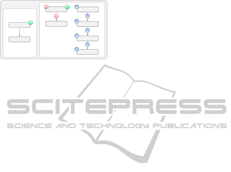
Management Patterns consist mainly of two parts
shown in Figure 2: (i) Target Topology Fragment (left)
and (ii) Topology Transformation (right). Target topol-
ogy fragments are used to analyze if a pattern can be
applied to a certain ASM while topology transforma-
tions apply the pattern to ASMs. In addition, they
provide information such as name, icon, or a textual
description following the pattern format of Hohpe and
Woolf (Hohpe and Woolf, 2003). In the following, we
explain these two main parts in detail.
2.1.1 Target Topology Fragment
A Target Topology Fragment defines a topology con-
CLOSER2013-3rdInternationalConferenceonCloudComputingandServicesScience
476
Topolo
( WAR )
( * )
(HostedOn)
( WAR )
( Tomcat )
(HostedOn)
(HostedOn)
( Amazon EC2 )
(HostedOn)
F
Migrate-WAR-To -Amazon Pattern
+
( WAR )
( * )
(HostedOn)
F
+
+
+
+
+
( Ubuntu Linux )
+
X
X
Target Topology Fragment Topology Transformation
Figure 2: Management Pattern which migrates a Java Web
Application to Amazon EC2.
taining components and relations which are the target
of the management task represented by the pattern.
This fragment is used for matchmaking between the
components and relations contained in the ASM and
the ones that are the target of the pattern. Thus, frag-
ments can be used to find Management Patterns which
are applicable to a certain ASM. A detailed description
of this matchmaking is given in Section 2.3. For visu-
alizing topology models we use Vino4TOSCA (Bre-
itenb
¨
ucher et al., 2012). Figure 2 shows an example
on the left: The shown pattern is applicable to ASMs
which contain a WAR-component hosted on any other
component. According to Vino4TOSCA, the type of
components and relations is emphasized by parenthe-
ses while
?
denotes wildcard, i. e., the corresponding
element is of any type. In addition, Focus-Annotations
on elements in the fragment are used to define which
components are affected directly by the pattern while
all other elements in the fragment only define the con-
text, e. g., the fragment in Figure 2 defines that only
the component of type WAR is affected directly and
not the component it is hosted on.
2.1.2 Topology Transformation
A Topology Transformation applies a pattern to an
Application State Model by transforming it into a De-
sired Application State Model. The transformation
gets three input parameters: (i) The ASM which has
to be managed by the pattern, (ii) a mapping which
maps elements of the ASM to elements contained in
the target topology fragment to indicate on which ele-
ments of the ASM the pattern has to be applied, and
(iii) pattern-specific parameters, e. g., a scale out pat-
tern needs to know how much additional components
should be created. The mapping is required because a
topology fragment possibly matches multiple different
parts of the model and this way the transformation gets
informed which one is the target. Applying a pattern
to a topology model may result in several structural
changes such as insertions, deletions, transformations,
and modifications of components or relations. To re-
flect these changes, patterns use Management Anno-
tations which represent low level management tasks
which have to be performed. Thereby, the complexity
of applying a high level management task is divided
into smaller tasks, which can be applied generically to
various kinds of applications.
Management Annotations are subdivided into two
disjoint classes: Structural Management Annotations
and Domain-Specific Management Annotations. The
first class represents annotations which structurally
change the topology and are used by patterns to indi-
cate which elements have to be created or removed: If
an element gets inserted by the pattern and has to be
explicitly instantiated, the element is annotated with
a Create-Annotation, if an element gets removed and
should be terminated, it is annotated with a Remove-
Annotation. If a Management Pattern inserts an al-
ready running component or instantiated relation, e. g.,
a database whose endpoint is known by the pattern,
it adds the respective element without the Create-
Annotation because no task has to be performed. Only
if the pattern wants to establish a new connection to
the already running database, this relation needs to be
inserted with attached Create-Annotation to indicate
that this has to be performed. Thus, the topology trans-
formation of the pattern shown in Figure 2 defines that
the focused element of type WAR and its hostedOn-
relation has to be removed and that a new application
stack has to be created on Amazon EC2.
In addition to structural modifications, the second
class of Management Annotations can be used to ex-
press domain-specific management tasks: A pattern
may annotate elements with Domain-Specific Anno-
tations to express low level management tasks of a
certain domain such as doing a database backup or
updating a component. Domain-Specific Annotations
may define several properties which can be used by
patterns to influence their processing, for example, a
Management Pattern doing database backups gets the
location to store the backups as input and writes this lo-
cation into a property of the Backup-Annotation to tell
the plan generator what to do. Thus, applying a pattern
on the one hand may change the topology structurally
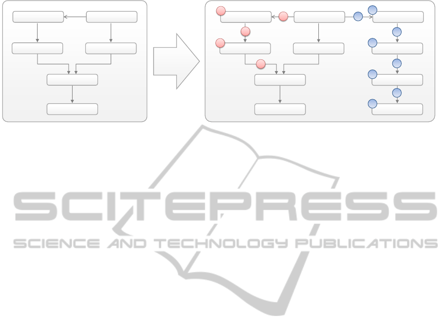
and on the other hand add domain-specific tasks. Fig-
ure 3 shows how the Migrate-War-To-Amazon-Pattern
of the previous section is applied to an example topol-
ogy: The ASM on the left gets transformed into the
DASM on the right. The structural annotations are
inserted by the transformation to define the low level
tasks which have to be performed. Components and
relations may have properties which hold information
such as the IP-address of a Web Server or the database
endpoint an application connects to. Patterns may add
Pattern-basedRuntimeManagementofCompositeCloudApplications
477
( PHP Application)
( Apache )
(HostedOn)
( Server )
(HostedOn)
( Windows 7 )
(HostedOn)
( WAR )
( Tomcat )
(HostedOn)
(HostedOn)
( PHP Application)
( Apache )
(HostedOn)
( Server )
(HostedOn)
( Windows 7 )
(HostedOn)
( WAR )
( Tomcat )
(HostedOn)
(HostedOn)
X
X
X
X
( Calls )
( Calls )
X
( WAR )
( Tomcat )
(HostedOn)
( Amazon EC2 )
(HostedOn)
( Ubuntu Linux )
(HostedOn)
+
+
+
+
+
+
+
( Calls )
+
Apply
Pattern
Figure 3: Transformation of an example ASM (left) to a DASM (right) by applying the Migrate-WAR-To-Amazon-Pattern.
properties to elements they create but they are not
allowed to remove or change attributes of already ex-
isting components and relationships. Thus, if a pattern
wants to change the database an application connects
to by replacing its endpoint, it has to attach a Domain-
Specific Management Annotation which represents
that task. To summarize, a topology transformation
may do the following five changes:
•
Insert explicitly new components and relations
with attached Create-Annotation
•
Insert already existing components and relations
without attached Create-Annotation
•
Remove components and relations by attaching the
Remove-Annotation
•
Define properties for components and relations
which are explicitly created
• Add Domain-Specific Management Annotations
2.2 Plan Generation
After the Desired Application State Model was created
by applying a Management Pattern, this model gets
transformed into a Management Plan. In this section,
we first describe different management layers which
differ in their management granularity. Furthermore,
we introduce a new layer called Management Planlets
which are used to encapsulate low level management
knowledge into reusable subprocesses. These Man-
agement Planlets are orchestrated by a plan generator
into a Management Plan that can be executed fully
automated to get the real running application into the
state defined by the Desired Application State Model.
2.2.1 Management Layers
In this section, we define three management layers
which differ in the level of granularity: (i) Manage-
ment Plans, (ii) Management Planlets, and (iii) Man-
agement Operations.
The highest management layer is provided by Man-
agement Plans which are workflows used to execute
management tasks fully automated. Management
Plans implement high level management functionali-
ties such as scaling out an application or the migration
of an application component from a private Cloud
into a public Cloud. They inherit features from work-
flow technology such as recoverability, compensation,
and fault mechanisms and offer a much more robust
and reliable way for application management than the
(manual) execution of scripts on a deep technical level.
One possibility to implement plans is provided by the
Business Process Execution Language, which is, e. g.,
used for the provisioning of applications (Keller and
Badonnel, 2004). Management Plans are typically cou-
pled very tightly to single applications and are there-
fore of limited value as they are sensitive to topology
changes and hardly reusable for the management of
other applications. In practice, application developers
create plans by hand and every change in the appli-
cation’s topology needs changing the corresponding
plans. In contrast to this, the lowest management layer
is represented by the so-called Management Opera-
tions, which are provided by components themselves.
These operations offer functionalities which are tightly
coupled to the components providing them such as
copying a file onto an operating system. They are or-
chestrated by Management Plans in order to provide a
higher level of management functionality.
Management Plans often need the same set of
lower level functionalities affecting multiple compo-
nents all at once such as installing an operating system
onto a virtual machine or functionalities aggregated
out of multiple single management operations offered
by a single component. To enable reuse, we intro-
duce Management Planlets. Planlets are subprocesses,
which cover these aggregated management functional-
ities in a reusable and self-contained way. Thus, they
can be used as generic building blocks for creating
Management Plans for different applications as they
are not coupled to individual applications. They are re-
CLOSER2013-3rdInternationalConferenceonCloudComputingandServicesScience
478
>
( PHP Application)
( Apache )
(HostedOn)
( Server )
(HostedOn)
( Windows 7 )
(HostedOn)
( WAR )
( Tomcat )
(HostedOn)
(HostedOn)
X
X
X
X
( Calls )
X
( WAR )
( Tomcat )
(HostedOn)
( Amazon EC2 )
(HostedOn)
( Ubuntu Linux )
(HostedOn)
+
+
+
+
+
+
+
( Calls )
+
( Amazon EC2 )
(HostedOn)
+
+
(HostedOn)
( Ubuntu Linux )
+
+
( Tomcat )
+
Annotated Topology Fragment
Workflow
Tomcat on Amazon Management Planlet
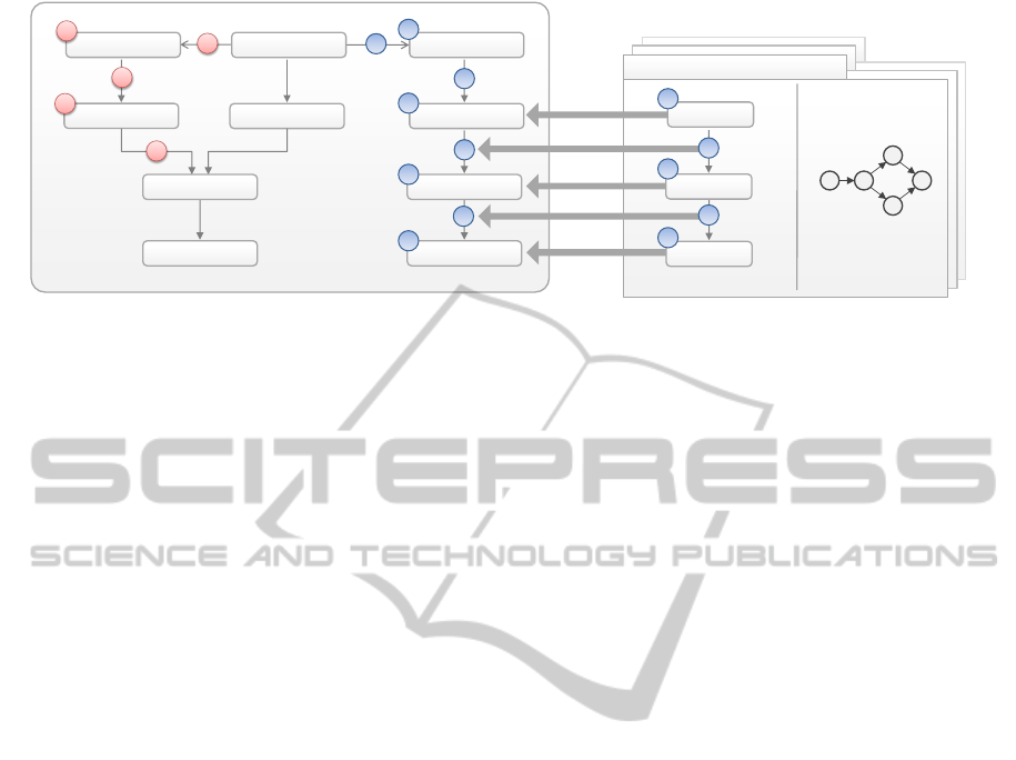
Figure 4: Matchmaking of elements in a DASM (left) and a Topology Fragment of a Management Planlet (right).
sponsible for managing small parts of applications but
are still on a higher level than management operations.
2.2.2 Management Planlets
In this section, we explain the concept of Management
Planlets and their structure in detail. Planlets are small
single-entry single-exit workflows which implement
low level management tasks involving multiple man-
agement operations such as installing a Web Server on
an operating system or copying files from one compo-
nent to another. A major requirement is that they can
be executed fully automated and support recoverability,
compensation, and transactional behaviour.
Each Management Planlet has an associated an-
notated topology fragment, similar to Management
Patterns. The Management Annotations in this frag-
ment represent the low level management tasks the
planlet executes on the respective elements and is used
by the plan generator to find an appropriate set of
Management Planlets whose execution transforms the
application into the desired state. For example, a frag-
ment may contain a single component of type MySQL-
Database with a domain-specific Backup-Annotation.
Thus, the planlet is responsible for doing this backup.
A detailed description for matchmaking of topology
fragments and state models is given in Section 2.3. Fig-
ure 4 shows the concept of Management Planlets visu-
ally. The planlet on the right defines the provided func-
tionality by an annotated topology fragment, which in
turn shows that the planlet creates an Amazon EC2
node, installs an operating system and thereon a Tom-
cat Web Server. As this combination of elements and
annotations is equally contained in the Desired Appli-
cation State Model on the left (indicated by the arrows
with checkmarks), the planlet can be used to perform
these tasks. The small plan on the right of the plan-
let indicates the workflow providing the functionality.
Management Planlets have typically several individ-
ual input parameters needed to perform the provided
tasks, e. g., credentials for Cloud providers needed
to acquire a VM. On the other hand, they create in-
formation such as the IP-address of the created VM
which may be needed by other planlets, e. g., if an-
other one shall install a Web Server on the acquired
VM. Thus, information needs to be shared between
planlets. To make this kind of runtime information
accessible for different planlets in a uniform manner,
Management Planlets also get a reference to a globally
accessible representation of the ASM, the DASM, and
an element mapping generated by the plan generator
as input. The latter maps the elements in the topology
fragment to the target elements in the ASM that shall
be managed by the planlet. The globally accessible
ASM is, therefore, used to store all runtime informa-
tion about applications. Thereby, planlets have access
to the affected elements of the ASM and may write
information directly to the properties of the respec-
tive elements which can be retrieved by other planlets.
Thus, Management Planlets get their information from
two sources: (i) their individual input parameters and
(ii) per extraction from the mapped elements of the ref-
erenced ASM and DASM. The mapping is also needed
to tell the planlet which elements are the target as an
ASM may contain multiple combinations of elements
matching the topology fragment of the planlet.
Beside the tasks, which are expressed by the anno-
tations, topology fragments also express which proper-
ties the planlet creates or removes on runtime. This is
done by attaching Create- or Remove-Annotations to
the respective property. If a planlet changes or updates
an already existing property of an element, it uses the
Create-Annotation as the effect of executing the plan-
let is the same as the property is instantiated with the
specified value. As there are many properties, such as
IP-addresses of components, to be instantiated which
can be determined not until runtime, fragments may
use wildcards to express that the planlet sets this prop-
erty with any value on runtime. This explicit modeling
of behaviour in terms of property handling is important
for the following plan generation as the applicability
Pattern-basedRuntimeManagementofCompositeCloudApplications
479

of a planlet may depend on preconditions considering
the existence of a certain property.
2.2.3 Orchestration of Planlets
In this section, we describe how a Desired Application
State Model gets transformed into an executable Man-
agement Plan which transitions the application into
the defined state through orchestrating Management
Planlets. Plan generation involves two issues: (i) Iden-
tifying which planlets can be used in (ii) which order
to create an efficient plan.
In general, graph covering techniques can be used
to find for a certain set of elements of the DASM a
suitable planlet to perform the tasks specified by the
annotations they have attached. This approach is lim-
ited as it allows applying only one planlet for each
element (component or relation) to get it in its desired
state. However, this is sufficient only for the deploy-
ment of applications (Eilam et al., 2011). Managing
applications typically needs more than one operation
per element, because it may have multiple annota-
tions which cannot be processed by a single planlet.
Thus, we cannot employ graph covering techniques as
an element may be in several different states before
it reaches its desired state and several planlets with
different tasks have to be executed to process all the
element’s annotations. A solution for this problem is
using planning techniques. Planning algorithms are
used to find a certain order of actions which transform
a given initial model, which represents the current state
of a system, into a given desired state model, which
denotes the goal state of the system to be achieved.
The advantage of these techniques in contrast to graph
covering is that they enable multiple actions on a sin-
gle element to get it into its desired state. A planning
algorithm has in general three input values: (i) A de-
scription of the initial world state, (ii) a description of
the desired goal, and (iii) a list of atomic actions of a
certain planning domain which can be used to trans-
form the initial model to the model representing the
desired goal (Weld, 1994). Actions change the state
of the system and have preconditions which must be
fulfilled to enable the execution of the action and post-
conditions expressing effects on the state of the system
which hold if the action was executed successfully.
We employ a Partial Order Planning (POP) algo-
rithm which searches the plan space and generates a
partially ordered plan of actions (Weld, 1994). The
partial order is used to improve the performance of a
generated plan as actions are executed in parallel if pos-
sible. We map its concepts to our approach as follows:
(i) The initial state is represented by the Desired Ap-
plication State Model which was created by applying
a pattern. (ii) The goal state is defined as the input De-
sired Application State Model without all annotations.
Thus, the goal is processing all annotations by actions.
(iii) An action is implemented by a planlet. Thus, the
goal of planlets is processing annotations. (iv) The
types and annotations of components and relations
defined in the topology fragment of a planlet as well
as their properties are treated as preconditions which
have to be fulfilled by the corresponding elements
in the current state model. (v) Each annotation on a
component or relation in the topology fragment of the
planlet is processed by the planlet and removed from
the state model after processing. Thus, this removal is
an effect as well as setting element properties which
are annotated with the Create-Annotation: These prop-
erties are set or updated by the planlet and thus also
effects on the state they are applied. To match the
preconditions of actions, i. e., the topology fragment
of a planlet, with the current state we use a (sub)graph
isomorphism algorithm called VF2. A detailed expla-
nation of this matchmaking is provided in Section 2.3.
In each step the POP algorithm adds an action, i. e., a
planlet, to the partial plan, it attaches the respective
mapping of elements in the ASM to elements of the
topology fragment. This is needed to tell the planlet
for which elements in the current state it is responsible
for (see Section 2.2.2).
If the POP algorithm terminates successfully it
outputs a partially ordered plan consisting of several
Management Planlets with attached element mappings.
This plan gets then transformed into an executable
Management Plan in the following way:
•
All causally ordered planlets are executed in se-
quence, all others in parallel
•
Specific input parameters of planlets are exposed
to the input message of the generated plan and
mapped back to the planlet’s input message
•
Each planlet gets the reference to the globally
accessible ASM as well as the respective target-
element mapping as input
Thus, the generated plan may have several individ-
ual input parameters such as credentials or security
configurations which have to be set. All other run-
time information the planlets produce and retrieve are
shared over the globally accessible ASM.
The concept of Management Annotations de-
creases the runtime of the algorithm as each action
processes at least one annotation and, thus, brings the
state one step closer to the final desired goal state
where all annotations were processed. In addition, we
assume that the number of actions for a certain par-
tial plan during the search is small as there is no need
to implement multiple planlets processing the same
annotations on the same combination of elements.
CLOSER2013-3rdInternationalConferenceonCloudComputingandServicesScience
480

2.3 Topology Fragment Matchmaking
For matchmaking of topology fragments and elements
in (Desired) Application State Models we use the VF2
algorithm presented by Cordella et al. (P. Cordella
et al., 2004). VF2 is a deterministic matching method
for verifying isomorphism as well as subgraph isomor-
phism between two graphs. To employ this algorithm,
we have to define the compatibility of elements. As
nodes and relations have types, annotations, and prop-
erties, we do not distinguish between them and refer
to both as element. Two elements are compatible iff
the following conditions hold:
•
The annotations of the element in the topology
fragment must be a subset of the annotations of the
element in the Desired Application State Model.
•
Each property of the topology fragment element
must have a wildcard as value, equally contained
in the properties of the element in the DASM, or
being annotated with the Create-Annotation.
•
The type of the element in the topology fragment
must either be defined as wildcard, exactly the
type of the element in the DASM, or any of its
descending sub types
For matchmaking of Management Planlets, which call
operations provided by management interfaces of com-
ponents, these conditions are also sufficient as the set
of interfaces a component provides is defined by its
type, e. g., each component of type Java Web Server
offers certain well-defined interfaces to deploy WAR-
files. Thus, the matchmaking does not need to consider
interfaces and operations separately.
3 EVALUATION
To evaluate the approach we implemented a Java
prototype which employs the Topology and Orches-
tration Specification for Cloud Applications, short
TOSCA (OASIS, 2012). TOSCA provides a portable
format to describe application topologies and man-
agement plans (Binz et al., 2012). A TOSCA Cloud
Service Archive (CSAR) packages a ServiceTemplate,
which describes the topology, and all required software
artifacts to provide the components, i. e., functional
artifacts and so-called ImplementationArtifacts imple-
menting the component’s management operations. For
ImplementationArtifacts, the system currently sup-
ports Java Axis Web Services. During importing a
CSAR, the management operations are provided au-
tomatically through deploying the Implementation-
Artifacts and the generated Management Plans get
bound to these operations automatically. The system
employs two repositories, one contains patterns, the
other planlets. Pattern topology transformations are
implemented in Java while planlets are implemented
in BPEL. Topology fragments are represented as an-
notated TOSCA ServiceTemplates. The prototype pro-
vides a runtime database used to store ASMs which
can be accessed by Planlets. To deploy applications,
a standard pattern is provided which annotates all el-
ements in the ASM with Create-Annotations. The
topology fragment of this pattern is completely empty,
thus, it matches all models. A termination pattern is
provided similarly. To customize and influence the
generated plans, we enable developers to store their
own planlets in CSARs. These planlets have a higher
priority as the planlets in the repository and the plan
generator uses them if possible. We implemented var-
ious patterns and planlets, e. g., for migrating a Java
Web Application to Amazon to prove the approach.
4 RELATED WORK
The work of (Eilam et al., 2011) focuses on deploy-
ment of applications and is similar to our approach for
the actual low level operation logic as they attempt to
bridge the gap between imperative logic implemented
as scripts and workflows and a declarative model rep-
resenting the desired state. The subject of their work
is the automated transformation of this desired state
model into a partially ordered workflow model by us-
ing so-called automation signatures which are similar
to planlets. Their workflow generation algorithms are
based on graph covering techniques, which limit the
approach to deployments where only one single oper-
ation is needed to get a resource in its desired state.
This is not sufficient for management as it needs inter-
mediary planning states as discussed in Section 2.2.3.
In a previous work (Maghraoui et al., 2006) the
authors present an approach based on AI Planning
similar to our workflow generation. However, this
work orchestrates provisioning operations provided
by existing provisioning platforms and is, thus, much
more restricted than using planlets and management
operations provided by the application components
themselves. In contrast to both works, our approach
enables the application developer to provide own man-
agement logic contained in CSARs by implementing
own Management Operations and planlets. Thus, we
introduce an additional level of granularity and provide
reusable customization possibilities for plan genera-
tion. In addition, both works focus only on deployment
and assume a desired state model as input which is in
our approach generated by applying patterns.
The work of (Arnold et al., 2007) presents a plat-
Pattern-basedRuntimeManagementofCompositeCloudApplications
481

form supporting the construction of DASMs for de-
ployment. They use model-based patterns to capture
abstract deployment topologies. In contrast to our
work, they focus on deployment and creating DASMs
by composing topology patterns. We apply transfor-
mation patterns to transform ASMs to DASMs.
The CHAMPS System (Keller et al., 2004) focuses
on Change Management which modifies IT systems
through so-called Requests For Change (RFC), e. g.,
installation, upgrade, or configuration requests. RFCs
are on a lower level than Management Patterns and
targeted to a single component or small group of com-
ponents while Management Patterns are intended to
affect multiple components directly at once. After re-
ceiving an RFC, the CHAMPS System assesses the
impact of the RFC on components by analyzing the de-
pendencies between the directly affected components
and their neighbours and generates a so-called Task
Graph which is afterwards used to generate an exe-
cutable Change Plan. Thus, the Desired Application
State Model is not generated by a single operation like
applying a Management Pattern but evolves by ana-
lyzing the influences of an RFC to other components
recursively. In contrast, we enforce a strict separa-
tion between change requests, which are expressed
as patterns in our work, the Desired Application State
Model, and the operational model which is represented
by planlets. This allows capturing high level expert
knowledge much more concrete in the automated exe-
cutable transformations of patterns.
The DevOps community also provides higher level
tooling such as Marionette Collective. These tools pro-
vide more convenience to manage application topolo-
gies as it turned out that large and complex topologies
are hard to manage with plain configuration manage-
ment only (Loope, 2011). The larger the topologies,
the higher the probability of mistakes when reusing ar-
tifacts. However, all these tools do not provide the high
level of abstraction provided by Management Patterns.
5 CONCLUSIONS AND
OUTLOOK
In this paper, we presented how high level and low
level management tasks can be implemented separately
in a generic and reusable manner by using Manage-
ment Patterns and Management Planlets and that they
are applicable fully automated to different applications.
To evaluate the approach, we implemented a prototype
based on TOSCA and showed that the concept also
enables application developers to influence the actual
management by implementing custom Management
Planlets. In future work, we plan to extend the sys-
tem towards applying patterns fully automated based
on certain application states and rules, e. g., to handle
peak workloads. In addition, multiple patterns should
be applicable at once.
ACKNOWLEDGEMENTS
This work was partially funded by the BMWi project
CloudCycle (01MD11023).
REFERENCES
Alexander, C. et al. (1977). A Pattern Language. Towns,
Buildings, Construction. Oxford University Press.
Arnold, W., Eilam, T., Kalantar, M., Konstantinou, A. V., and
Totok, A. A. (2007). Pattern based SOA deployment.
In ICSOC. Springer-Verlag.
Binz, T., Breiter, G., Leymann, F., and Spatzier, T. (2012).
Portable Cloud services using TOSCA. IEEE Internet
Computing, 16(03):80–85.
Breitenb
¨
ucher, U., Binz, T., Kopp, O., Leymann, F., and
Schumm, D. (2012). Vino4TOSCA: A visual notation
for application topologies based on TOSCA. In CoopIS.
Springer-Verlag.
Eilam, T., Elder, M., Konstantinou, A. V., and Snible, E. C.
(2011). Pattern-based composite application deploy-
ment. In Integrated Network Management. IEEE.
Hohpe, G. and Woolf, B. (2003). Enterprise Integration Pat-
terns: Designing, Building, and Deploying Messaging
Solutions. Addison-Wesley.
Keller, A. and Badonnel, R. (2004). Automating the pro-
visioning of application services with the BPEL4WS
workflow language. In DSOM. Springer.
Keller, A., Hellerstein, J. L., Wolf, J. L., et al. (2004). The
CHAMPS system: change management with planning
and scheduling. In NOMS. IEEE.
Loope, J. (2011). Managing Infrastructure with Puppet.
O’Reilly Media, Inc.
Maghraoui, K. E., Meghranjani, A., Eilam, T., and Konstanti-
nou, E. V. (2006). Model driven provisioning: Bridg-
ing the gap between declarative object models and
procedural provisioning tools. In ACM/IFIP/USENIX
Middleware 2006.
OASIS (2012). Topology and Orchestration Specification
for Cloud Applications Version 1.0 Committee Specifi-
cation Draft 03.
P. Cordella, L., Foggia, P., Sansone, C., and Vento, M. (2004).
A (sub)graph isomorphism algorithm for matching
large graphs. IEEE Trans. Pattern Anal. Mach. Intell.,
26(10):1367–1372.
Weld, D. S. (1994). An introduction to least commitment
planning. AI Magazine, 15(4):27–61.
CLOSER2013-3rdInternationalConferenceonCloudComputingandServicesScience
482
