
Hierarchical Supporting Structure for Dynamic Organization in
Many-core Computing Systems
Liang Guang
1
, Syed M. A. H. Jafri
1,2
, Bo Yang
1
, Juha Plosila
1
and Hannu Tenhunen
1,2
1
University of Turku, Turku, Finland
2
Royal Institute of Technology, Stockholm, Sweden
Keywords:
Many-core Systems, Dynamic Organization, Dependability, Software/Hardware Co-design.
Abstract:
Hierarchical supporting structures for dynamic organization in many-core computing systems are presented.
With profound hardware variations and unpredictable errors, dependability becomes a challenging issue in the
emerging many-core systems. To provide fault-tolerance against processor failures or performance degrada-
tion, dynamic organization is proposed which allows clusters to be created and updated at the run-time. Hier-
archical supporting structures are designed for each level of monitoring agents, to enable the tracing, storing
and updating of component and system status. These supporting structures need to follow software/hardware
co-design to provide small and scalable overhead, while accommodating the functions of agents on the cor-
responding level. This paper presents the architectural design, functional simulation and implementation
analysis. The study demonstrates that the proposed structures facilitate the dynamic organization in case
of processor failures and incur small area overhead on many-core systems.
1 INTRODUCTION
With constant technology scaling, many-core com-
puting systems have become a reality (Vangal et al.,
2008). By exploiting massive parallelism, such sys-
tems are expected to provide much higher theoretical
performance than single-core or few-core chips. For
instance, TeraFLOPS (Vangal et al., 2008), an 80-core
processor, achieves over 1.0 TFLOPS ( 10
12
floating-
point operations per second). To provide interconnec-
tion in a scalable manner, Network-on-Chip (NoC)
is widely adopted as the communication architecture
for many-core systems (Jantsch and Tenhunen, 2003;
Vangal et al., 2008). In particular, regular network
layout (e.g. mesh) with predictable link delay and
electrical properties are favoured for general-purpose
NoCs (Pamunuwa et al., 2004).
Dependability is a major design challenge on
many-core systems. While an increasing number of
resources can be integrated onto a single die, the fault
occurrence is also rising (Shamshiri et al., 2008). For
one thing, due to the small feature size, process vari-
ation and aging, the probability of permanent and
transient faults increases in VLSI chips (Collet et al.,
2009). For another, the deviation in the supply volt-
age and threshold voltage may lead to longer criti-
cal paths and consequent worse performance (Unsal
et al., 2006). When certain resources in a many-
core system fail, the system should still properly per-
form with the remaining resources, in order to pro-
vide dependable computing and improve the yield
(Shamshiri et al., 2008).
Hierarchical agent-based adaptation (H2A) is a
systematic and generic approach to achieve self-
adaptive parallel computing (Guang et al., 2010).
Software and hardware agents are embedded on dif-
ferent organization levels, to monitor and reconfig-
ure global and local services, including energy man-
agement and dependable computing. The top-level
agent, platform agent, is responsible for system-level,
coarse-grained resource allocation. Regional-level
agents, cluster agents, are managing intra-cluster ser-
vices, e.g., energy management. In particular, the
agents need to enable run-time resource reconfigura-
tion in case of component failures.
This paper proposes hierarchical supporting struc-
tures on agent-based many-core systems, to enable
the run-time status tracing, storing and updating. We
present the concept of dynamic organization, which
allows a cluster to be dynamically created and up-
dated in case of permanent failures or performance
degradation. In addition, to offer scalability towards
100s-1000s future chips, the structures need to follow
software/hardware (SW/HW) co-design techniques to
252
Guang L., M. A. H. Jafri S., Yang B., Plosila J. and Tenhunen H..
Hierarchical Supporting Structure for Dynamic Organization in Many-core Computing Systems.
DOI: 10.5220/0004389702520261
In Proceedings of the 3rd International Conference on Pervasive Embedded Computing and Communication Systems (SANES-2013), pages 252-261
ISBN: 978-989-8565-43-3
Copyright
c
2013 SCITEPRESS (Science and Technology Publications, Lda.)

reduce the overhead. We will present the architec-
ture design, SW/HW co-synthesis, simulation and im-
plementation analysis for the hierarchical supporting
structures.
The rest of the paper is outlined as follows: Sec-
tion 2 describes the most relevant existing works.
Section 3 explains dynamic organization in H2A plat-
forms. Section 4 presents the architectural design and
implementation of the hierarchical supporting struc-
tures. Section 5 presents functional simulation and
implementation overhead analysis. Section 6 dis-
cusses the assumption of fault types. The paper is
concluded in Section 7.
2 RELATED WORK
Core-level redundancy is a well-proven technique for
fault-tolerance and dependability in many-core sys-
tems. (Zhang et al., 2008) proposes to employ core-
level redundancy in homogeneous many-core sys-
tems. In particular, it presents reconfiguration heuris-
tics to transform any physical topologies into a unified
logic topology. In this way, core failures will lead
to the same network topology as seen by the oper-
ating system and the programmer. (Shamshiri et al.,
2008) identifies that employing spares for in-field re-
covery can improve the manufacturing yield and re-
duce the overall cost. (Chou and Marculescu, 2011)
presents resource management techniques on NoCs to
address several fault-tolerance metrics (e.g. weighted
Manhattan distance and link contention). While these
works provide a foundation for utilizing core-level re-
dundancy, this paper focuses on the dynamic organi-
zation against failures in a hierarchically monitored
system.
Clustering, instead of deploying an algorithm or
a configuration on the whole system, is a technique
to improve application performance and efficiency in
parallel and distributed systems. (Lu et al., 2008)
proposes a fast simulated annealing based approach
for application mapping on NoCs. It narrows the
search space from the whole NoC down to network
regions (clusters), thus significantly reduces the tim-
ing complexity of the mapping algorithm. (Guang
et al., 2009) proposes clustering algorithm to locate
network regions with similar traffic density, so that
the same frequency can be applied within these clus-
ters to reduce the synchronization overhead. For any
clusterization algorithms, the system needs to trace
the run-time organization for future reconfiguration.
The hierarchical supporting structure proposed in this
paper is a systematic and low-complexity approach to
enable the dynamic clusterization process.
Our previous work (Guang et al., 2010) presents
hierarchical agent-based architecture for parallel and
embeddedsystems. It proposed the initial idea of trac-
ing system parameters using look-up tables. How-
ever, our work at that stage had not concretely for-
mulated the motivation and architectural design of
dynamic organization in the agent-based platform.
Another existing work (Ostroumov and Tsiopoulos,
2012) presents formal-method-based design of the
hierarchical agent architecture, formulating agents’
functions in managing run-time faults. Compared to
these previous efforts, this paper presents the architec-
tural design of the hierarchical supporting structures,
and proposes SW/HW co-synthesis of these structures
based on the implementation of agents on the cor-
responding level. Functional simulation and imple-
mentation overhead analysis are provided to further
demonstrate the proposed structures.
3 DYNAMIC ORGANIZATION
To provide efficient and scalable management, a
many-core system can be hierarchically organized. To
account for the processor errors and failures, such or-
ganization needs to be dynamically created and main-
tained. This section motivates and overviews dy-
namic organization in hierarchically agent-based par-
allel systems.
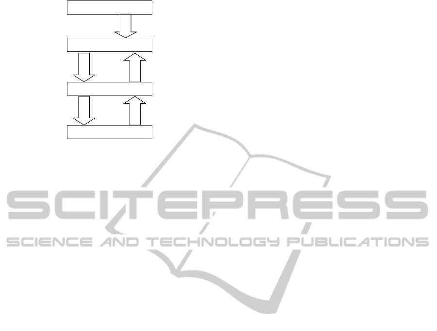
3.1 Hierarchical Agent-based
Adaptation
Hierarchical Agent-based Adaptation (H2A) is a scal-
able design approach for self-aware and adaptive sys-
tem. An overview is provided based on the previous
work (Guang et al., 2010) (Fig. 1).
The system is monitored, at the highest level, by
the platform agent, which is responsible for coarse-
granular system management. The platform agent is
aware of all the available resources, and can provide
run-time resource allocation. To alleviate the moni-
toring and control bottleneck of the platform agent,
the system is divided into a number (application-
specific) of clusters. Each cluster is a group of com-
ponents, and may execute a particular application in a
multi-application system. The cluster agent monitors
and decides on the intra-cluster configuration, e.g.,
power management or energy-performance tradeoff.
Each component in a cluster, a cell, as the basic
organizational unit, is monitored by one cell agent.
The cell agent senses the local component status, re-
ports to the cluster or platform agents, and actuates
HierarchicalSupportingStructureforDynamicOrganizationinMany-coreComputingSystems
253
Application
Platform Agent
Manage
clusters
Application
requirements
Cluster
performance
Generic Functional Partition
System-level Resource allocation
e.g. Mapping,
fault-triggered remapping,
Implementation
Cluster Agent
Manage cells
Cell
performance
Cell Agent
Intra-cluster resource
configuration
energy management
e.g. Run-time energy-
performance tradeoff
Software
e.g. microprocessor
Software/hardware Co-
design
e.g. Software thread plus
hardware accessory
Hardware
Local monitoring
and actuating
Figure 1: Overview of Hierarchical Agent-based Adaptation.
the configuration. The hierarchical function parti-
tioning among agents is designed to serve both lo-
cal and global services on specific levels. To offer
physical scalability in terms of agent overheads, soft-
ware/hardware (SW/HW) co-design is applied to dif-
ferent level of agents. Given the diversity of services
for system-level management, software-based design
(i.e., a dedicated core) is a proper design choice for
the platform agent. For the cell agents, as local ser-
vices are usually modular and fast, hardware-based
design is suitable. Cluster agents, with intermediate
granularity, may combine both software and hardware
components to tradeoff flexibility and speed.
3.2 Agent-based Dynamic Organization
As processing cores suffer from unpredictable fail-
ures, clusters in H2A architecture need to be dynam-
ically reconfigured. Broken cells need to be removed
from a cluster, with proper replacement of spares. In
addition, the performance of clusters may degrade,
e.g. when the working frequency decreases due to the
variation of threshold voltage (Borkar et al., 2003). In
this case, spares may be integrated into a cluster to
speed up the application. The dynamic organization,
which provides dependable computing in case of pro-
cessor failures or performance degradation, requires
agents and their affiliated structures to track the run-
time organization and system parameters.
A motivational example, illustrated with the NoC
platform, is given in Fig. 2. The dynamic organiza-
tion involves a monitoring, decision-making and re-
configuration process:
• Monitoring. This stage identifies processor fail-
ures or variation-inducedtiming errors (leading to
performance degradation). The detection of pro-
cessor failures can be performed in a variety of
manners, for instance, by running test programs
on a processor to compare the outputs (Oh et al.,
2002). In addition, the timing errors induced by
the process variations can also be detected by
comparing the register output with a delayed latch
output (Das et al., 2009). Such run-time test-
ing can be issued by the platform, cluster or cell
agents, for instance, by temporarily taking a pro-
cessor from normal operation and running the test
program. As the testing techniques for processor
failures are beyond the scope of this paper, it is
assumed that cell agents can detect processor fail-
ures and notify their occurrences to the platform
agent.
• Decision-making. As the platform agent is aware
of all cells’ status (Section 4 will explain how),
it is the platform agent that decides on a proper
spare for a cluster with broken cells. The choice
can be made, for instance, to minimize the total
communication energy after replacement. If nec-
essary, a complete application remapping can be
performed for the involved cluster. The removal
of broken cells and the replacement of spares will
be actuated in the reconfiguration stage.
• Reconfiguration. In particular, spares for replace-
ment will be notified of the cluster agent’s loca-
tion. Similarly, the cluster that receives new cells
will be updated with the cells’ locations. The re-
configuration not only applies to spares, but also
to cells that are reconfigured to a different clus-
ter. In case a system is short of resources ac-
commodating all applications, the platform agent
may decide to reallocate a processor from a lower-
prioritized cluster (based on its application) to a
cluster running a more critical task.
The partitioning of agents’ roles can be flexibly
designed. Here the choice of spares is made by the
platform agent to prevent conflicts when two cluster
agents attempt to utilize the same spare. As an al-
ternative, if spares are reserved for specific clusters,
PECCS2013-InternationalConferenceonPervasiveandEmbeddedComputingandCommunicationSystems
254

the allocation of spares can be made as part of cluster
agents’ services.
4 HIERARCHICAL SUPPORTING
STRUCTURE
As agents are implemented with SW/HW co-design,
specific supporting structures are needed to facilitate
the agent-based dynamic organizationprocess. In par-
ticular, the run-time tracing, storing and updating of
cell/cluster/platform status need to be realized with
simple, low-overhead and scalable designs. This sec-
tion will present the hierarchical supporting structures
with proper SW/HW co-synthesis as suitable to the
corresponding level of agents.
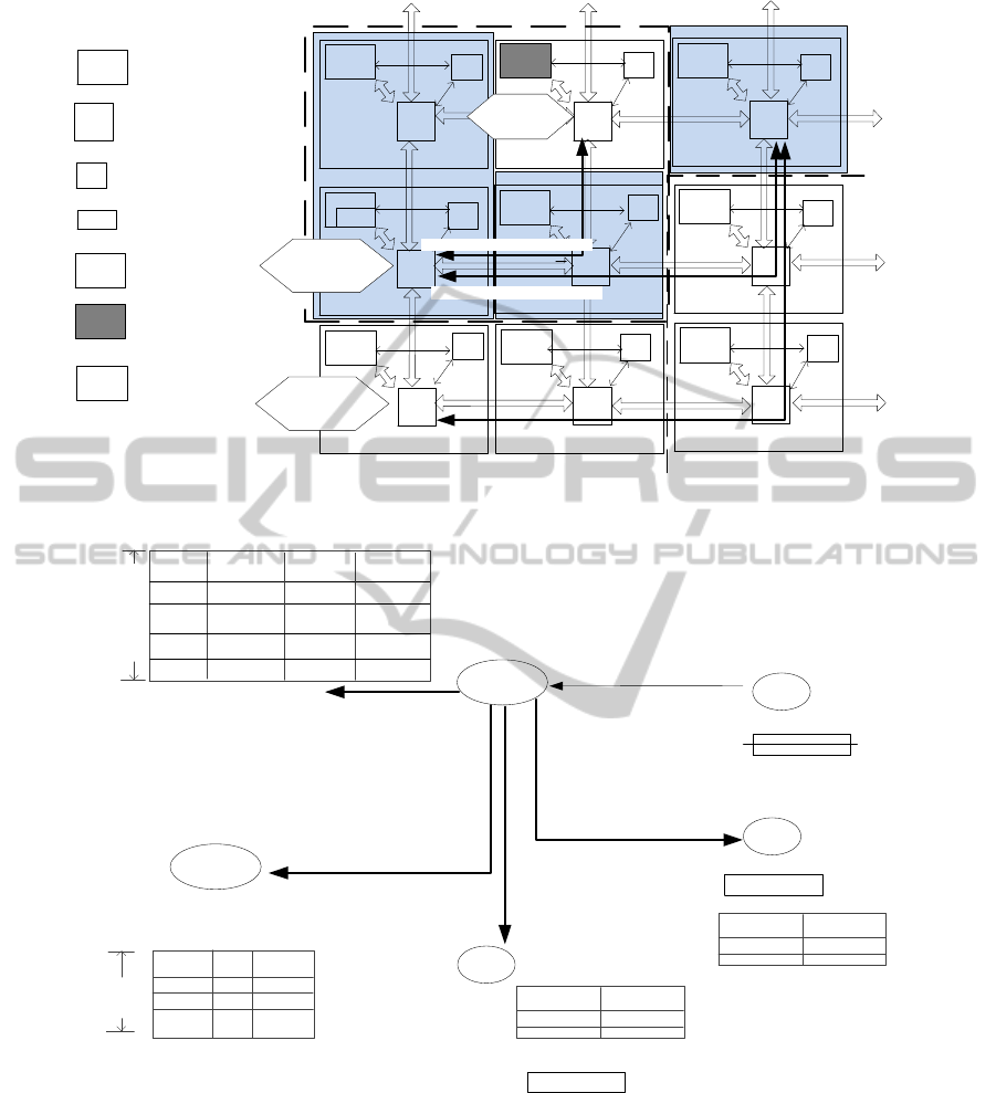
4.1 Functional Design
The supporting structures include Resource Look-up
Table (RLT) on the platform agent, Cluster Look-up
Table (CLT) on the cluster agent, Cluster Identifier
Register (CIR) and Re-Routing Table (RT) on the cell
agents. Fig. 3 illustrates the functional overview of
these structures.
The system is initially configured with a number
of spare cells, and divided into a number of clus-
ters, e.g. one cluster for one application. At the run-
time, before loading a new stream (assuming stream-
ing applications without implying restrictions), all
cell agents perform a self-test. Any processor failure
will be notified to the platform agent. Upon receiving
the fault status, the platform agent attempts to locate
the most suitable spare cell for the broken cell. As
the platform agent is aware of the processor status in
all clusters, it can assign the spare cells without lo-
cating the same spare in two clusters. Based on the
replacement decisions, the platform agent continues
with dynamic organization. It writes the CIR of the
chosen spare cell with the address of the cluster agent.
The RT of each router is also updated by the platform
agent, so that the spare cell’s address will replace that
of the broken cell. For the cluster agent, the platform
agent updates its CLT by removing the broken cell
and adding the new cell. Lastly, the platform agent
updates its own RLT, based on the new cluster infor-
mation. Then on the properly configured platform,
a new stream can be processed, with other potential
services, e.g. energy management. The initial clus-
terization is decided by the platform agent, and will
be actuated via configuring the RLT, CLT and CIR.
Spares can be allocated per system, with the platform
agent deciding on the suitable spare cell. As an al-
ternative, if spares are reserved for each cluster, the
cluster agent can decide on the proper spare cell.
Detailed structures of RLT, CLT and CIR are as
follows:
• Resource Look-up Table (RLT). Affiliated with
the platform agent, RLT is a reconfigurable stor-
age of all cells’ monitored parameters, which are
accessible to the platform agent. As illustrated in
Fig. 3, RLT has the number of entries as large as
the total number of cells in the system. In each
entry, fields related to the cell’s utilization status
(used or spare) and fault status (proper or broken).
The utilization and fault status are needed for the
platform agent to determine the mapping, for in-
stance, choosing the closest replacement for a bro-
ken core. The entries in RLT are updated by the
platform agent, either upon receiving new cell sta-
tus from the cell agents, or after the platform agent
decides on a new clusterization.
• Cluster Look-up Table (CLT). On each cluster
agent, CLT holds the status of cells currently al-
located to the cluster, and the information of ap-
plication(s) currently running in the cluster. As
illustrated by Fig. 3, the number of entries in
CLT is the number of cells and applications al-
located to the cluster. Any broken cell will be
cleared by removing its entry in CLT. Each en-
try for cells include the cell ID (the address of
the cell in the network), and the run-time param-
eters (usually design specific such as buffer load,
cache hit rate). The run-time parameters are used
for adaptive optimization. For instance, the buffer
load can indicate network congestion in energy-
performance trade-off. Each entry for applica-
tions include the application ID and timestamps of
monitored milestones (e.g., the starting/end time).
Compared to the content in RLT, CLT does not
include the fields of cell utilization and fault sta-
tus, as all cells stored in CLT are actually being
utilized. When new cells are allocated to a clus-
ter, or broken cells are removed from the cluster,
the platform agent will update the CLT accord-
ingly. On the other hand, the run-time optimiza-
tion (such as the energy management) is done at
the cluster level, thus the cell and application pa-
rameters, as reported by each cell agent, are stored
only in the CLT.
• Cluster Identifier Register (CIR) and Re-routing
Table (RT). On each cell agent,there is a CIR,
which stores the location of the cluster agent. As
a cell (utilized or spare) can be allocated to any
cluster at the run-time, CIR, being reconfigurable
by the platform agent, is written with the current
cluster agent’s address. In addition, to support the
data communication after fault-triggered remap-
HierarchicalSupportingStructureforDynamicOrganizationinMany-coreComputingSystems
255
Decision-Making/
Spare replacement
R.
S
R.
PE
R.
PE
R.
CEA
R.
CEA
R.
R.
PE
CEA
R.
PE
R.
S
CLA
CEA
CEA
CEA
CEA
CEA
Processing
element
Router
Cell agent
Cluster agent
Platform agent
CEA
Original Cluster
PLA
Other Clusters
PE
R.
CEA
CLA
PLA
Processor failure
S
Spare
Monitoring/
Fault
detection
Broken cell
removed/
Spare added
New Cluster
Spare added in cluster
Failed cell removed
Locating the best spare for
replacement
Figure 2: Monitoring, Decision-Making and Reconfiguration in Dynamic Organization.
Re-Routing Table (RT)
Broken
processor
1) Cell agent of the broken
cell reports the fault status
to the platform agent.
5)
CIR
Platform
Agent
Cell
Agent 1
Spare
Cluster Identifier Register (CIR)
Cell
Agent 2
Cluster Agent1
Cell
Agent 3
2) The platform agent
assigns the spare to
cluster agent 1
The platform agent removes the
broken cell from the cluster table,
and adds the new spare.
The platform agent updates its
own resource table.
Cell ID
Cluster ID
Fault status
Utilization
status
The number
of cells in
the platform
Cluster 1
Faulty
0
Cell 1
Resource Look-up Table (RLT)
Cluster 1
Proper
1
Cell 2
Cluster 1
Proper
1
Cell 3
For storing and tracing the status of
all cells
Load
Cell ID
Maximal
cluster size
Other
parameter
Cluster
Agent 1
Cluster Look-up Table (CLT)
Tracing the status of all CURRENT
cells in the cluster
4)
3) The platform agent updates
the re-routing table of cells
New
destination
Original
destination
Cell 1
Cell 3
CIR
Cluster Agent1
Cluster Agent1
Application
ID
Time
RT
New
destination
Original
destination
Cell 1
Cell 3
Figure 3: Functional Overview of Hierarchical Supporting Structures.
ping, a RT is attached to each router, which is also
written by the platform agent. When a broken pro-
cessor is replaced by a new processor, all packets
destined for the broken processor will be modified
with a new destination (in the header flit).
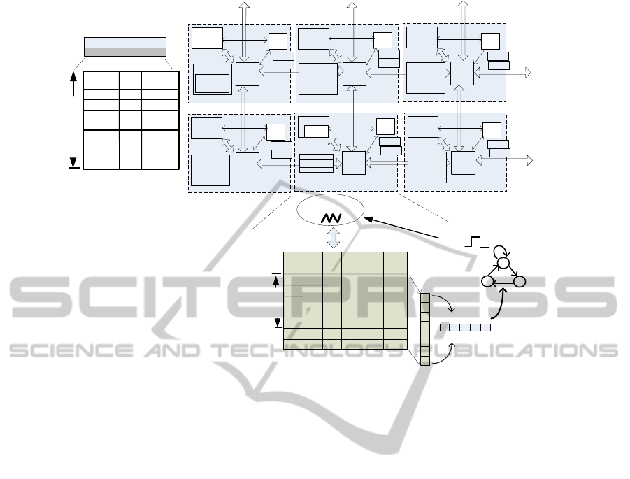
4.2 SW/HW Co-synthesis
Following the SW/HW co-design of agents, RLT is
implemented as part of the local memory of the plat-
form agent (software agent). CLT is implemented as
a pre-processing hardware unit for the cluster agent (a
thread on one processing core). CIR and RT are sim-
ply hardware registers in each cell. Fig. 4 presents
the SW/HW co-synthesis of the hierarchical support-
ing structures.
RLT, where utilization status of all cells is stored,
is implemented in the distributed memory of the plat-
PECCS2013-InternationalConferenceonPervasiveandEmbeddedComputingandCommunicationSystems
256
R.
R.
PE
R.
PLA
CEA
R.
PE
CEA
R.
PE
CEA
Memory
R.
PE
CLA
CLT
CEA
CEA
CEA
RLT
CIR
CIR
CIR
CIR
CIR
CIR
RT
RT
RT
RT
RT
RT
RLT
(1,0)
Status
(0,0)
used
faulty
(0,1)
spare
.
.
.
Cell index
1
used
(1,1)
Cluster
Agent
1
Local Memory
Memory
Memory
Memory
Wakeup
Interrupt_out=1
Cell 0
Cell 1
Row selection
mask (RSM)
Parameter
selection
mask
(PSM)
1
1
1
0
0
1
Cell 2
CLT
Cell/
Application
Application 1
Load
0.2
0.1
Updated Time
Updated:
Is the value updated?
1-updated; 0- old data
X
None-applicable
.
.
.
Application 2
0.1
1
X
X
Updated
X
X
X
X
X X
0 0
X X
500
0
0
Select the
interested
cells
0
0
1 0
0
Select the
interested
parameters
”00"
waiting
”01"
All loads
returned
”10"
Cluster Agent
Thread
The maximal
allowed number
of cells in one
cluster
Memory
PLA: Platform agent
CEA: Cell agent
CLA: Cluster agent
PE: processing element
R.: Router
RLT: Resource look-up table
CLT: Cluster look-up table
CIR: Cluster identifier register
RT: Re-routing table
Figure 4: SW/HW Co-synthesis of Hierarchical Supporting Structures.
form agent. Implementing RLT in the existing mem-
ory space instead of a dedicated hardware unit is
based on two-fold considerations:
• The size of RLT can easily fit into a distributed
memory space. The entry width of RLT is
log
2
N + 2 + log
2
N in bits, as the status field re-
quires 2 bits (3 states: faulty, used, spare) and
cell/cluster location each requires log
2
N bits (N
is the maximal number of nodes in NoC). Given
1000 nodes in NoC, each entry becomes 22-bit
wide covering 3 bytes. Even assuming an entry
uses one 32-bit memory line (e.g. Leon3 proces-
sor is 32b), the RLT can fit in 4KB memory space,
which is a small portion of common processor’s
memory space (for instance, a Leon 3 processor
in (Chen and Zhonghai, 2010) (Chen et al., 2010)
has 64KB local memory).
• ImplementingRLT in the distributed memory pro-
vides high flexibility for the platform agent to ac-
cess the table as memory operations. In addi-
tion, any processor can be configured as the plat-
form agent (during compilation). If RLT is im-
plemented as a dedicated hardware unit, only the
cells attached with RLTs can be configured as the
platform agent (unless a RLT is attached to every
node).
CLT is implemented as a pre-processing unit to
the cluster agent (Fig. 4). Each cluster agent is im-
plemented as a software thread, sharing a process-
ing core with computation threads. When the clus-
ter agent perform, e.g., energy-performance tradeoff,
it may wait on specific information (e.g., the local
loads), which suspends the thread. When the infor-
mation is sent from each cell agent, it will be stored
in the CLT. When a certain criteria is met, e.g., the
loads of all routers are returned, an output signal is
generated from CLT to wake up the suspended cluster
agent thread. Each entry of CLT contains the mon-
itored parameters of one cell or the timestamps of a
running application. At the run-time, these parame-
ters will be updated in an unpredictable order. The
local load of each router, as an example, may be re-
ported by the corresponding cell agent in a random
order. The interrupt triggering criteria can be dynam-
ically configured with RSM (row selection mask) and
PSM (parameter selection mask) (Fig. 4). The RSM
can be written by the cluster agent to choose the inter-
ested cells or applications. To choose the interested
parameters, the PSM can be configured by the clus-
ter agent. In case of dynamic organization, complete
entries in CLT will be updated. For instance, the row
for a broken cell will be replaced by one for the spare
cell.
HierarchicalSupportingStructureforDynamicOrganizationinMany-coreComputingSystems
257

Implementing CLT in hardware is an alternative to
the software-based implementation of a look-up table
(e.g., the RLT). The design choice is based on two-
fold considerations:
• The pre-processing unit only wakes up the thread
when all needed information is ready, instead of
triggering a context-switch every time one piece
of information is received. Such technique re-
duces the timing overheads caused by excessive
context switching.
• If the platform needs to support the scenario
where every node can host a cluster agent, one
CLT should be attached to each node. Consider-
ing 32-entry (thus accommodating 32 cells in the
cluster) 16-bit wide CLT, it only covers 2.2% of
a 64-bit router(Section 5). Surely the size of CLT
is application dependent, though its small over-
head can be clearly identified. Thus the hardware-
based CLT implementation is highly feasible.
As each cell agent is a hardware-based unit
wrapped within a NoC node, implementing RT and
CIR as registers becomes a natural design choice. It
should be noted that these registers are writable by the
platform agent. In the dynamic clusterization process,
CIR will be updated with the cluster agent address,
and the RT will be updated with the failure and spare
cells’ indexes.
5 QUANTITATIVE EVALUATION
With a registertransfer level implementation of many-
core systems, this section validates the function of the
proposed hierarchical supporting structures and ana-
lyzes the physical overhead.
5.1 Experimental Setup
Agents and the supporting structures are implemented
upon the McNoC platform (Chabloz and Hemani,
2012). The platform is composed of Leon 3 proces-
sors connected with mesh network-on-chip, as sim-
ilar to the illustration in Fig. 4. It adopts dis-
tributed shared memory. Each processor has 64KB
shared memory (Chen and Zhonghai, 2010) (Chen
et al., 2010). The network utilizes wormhole switch-
ing and hot-potato routing, as in Nostrum architecture
(Jantsch, ). Each router can be configured dynami-
cally with different voltages and frequencies based on
GRLS (globally ratiochronous, locally synchronous)
timing (Chabloz and Hemani, 2010). In particular,
any local clock needs to be rationally related to a ref-
erence clock (f
l
=
1
N
f
r
, N is an integer). Synthesis
of a router in 65nm CMOS technology identifies the
maximum speed of a router is 300MHz with 1.32V.
Thus four voltage and frequency pairs can be recon-
figured for each router: (300MHz, 1.32V), (100MHz,
1.1V), (50MHz, 1.1V) and (20MHz, 1.1V)
1
. The
agents and the hierarchical supporting structures are
implemented as described in Section 4.
5.2 Functional Simulation
To validate the function of the hierarchical supporting
structures, two streaming applications are simulated
on the experimented platform. The first application
is for image processing BASIZ (Roig et al., 2007),
which requires 26 cores, mapped on a 6 × 5 network
area and configured into one cluster. The other ap-
plication, MPEG encoding (Khan and Ahmed, 2008),
requires 21 cores. It is mapped on a 5 × 5 NoC area,
also configured into a cluster. Both clusters will con-
tain 4 spare cores as redundancy.
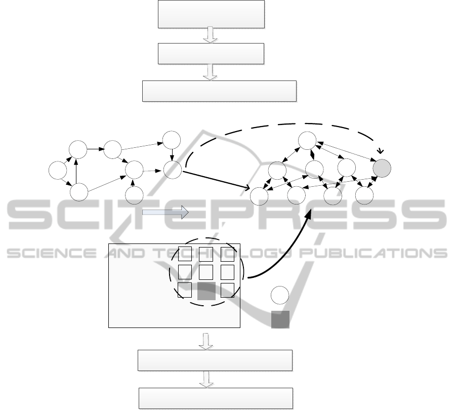
To simulate the dynamic organization, three ran-
dom processor failures are injected into each clus-
ter. As illustrated in Fig. 5, the many-core system
goes through the following reconfiguration: each ap-
plication is mapped onto the designated cluster with
randomly injected errors. The mapping utilizes tree-
model based mapping algorithm (Yang et al., 2010)
as an example of energy-aware mapping without im-
plying limitation. The RLT, CLT, CIR and RT (Sec-
tion 4) are accordingly configured. Afterwards each
cluster agent performs dynamic energy management
in each cluster. In particular, each cluster is initially
configured with the highest voltage and frequency
(300MHz, 1.32V). After one application stream com-
pletes, the cluster agent identifies the router with max-
imal load (measured as the buffer occupancy ratio in
any passed period), and then applies a lower level of
voltage and frequency. The dynamic energy manage-
ment is only designed to validate if the system works
properly after processor failures.
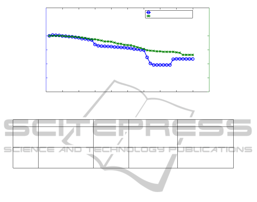
Fig. 6 illustrates the energy consumption of 45
streams of both applications after failure-triggered
dynamic organization. The energy value is normal-
ized with the energy consumption of the first stream
(highest voltage and frequency setting). It can be
observed that the energy management works prop-
erly in both clusters. The energy savings are 16.53%
and 13.62% respectively. This demonstrates that both
clusters maintain their functions with the processor
failures resolved by the dynamic organization.
1
The minimum supported voltage of the experimented
technology library is 1.1V.
PECCS2013-InternationalConferenceonPervasiveandEmbeddedComputingandCommunicationSystems
258
P1 P2
P0
P7
P5 P4
P6
V0
1
C07
V12
C23
C75
C65
C25
C34
C5
4
n5
n4
n8
n6
S
n1
n9
1) Mesh network with
spares abstracted as a tree
Processor failure injection
Initial setting
Spares in each cluster’ rectangle
S
n2
n5
n1
n2 n3
n4 n6
n8
n9
S Spare cell
n3
Tree-based Energy-Aware Remapping
P3
Updating RLT, CLT, CIR and RT
Dynamic Energy Management in Each
Cluster
Application
Chracterization Graph
n2
Broken cell
When error-free,
P4 should be
mapped to n2
P5
P2
2) map the application on
the tree with spares
P7
P6
P
4
m
a
p
p
e
d
t
o
t
h
e
n
e
x
t
n
o
d
e
i
n
t
h
e
t
r
e
e
i
n
s
t
e
a
d
P4
P1
P0
P3
Figure 5: Functionally Validating Dynamic Organization.
5.3 Overhead Analysis
The overheads of RLT and CLT need to be analyzed
differently. RLT is a memory-mapped look-up table,
and each entry can fit into a 32-b memory line (Sec-
tion 4.2). Therefore, the overhead of RLT can be an-
alyzed as a percentage of the platform agent’s local
memory. CLT, on the other hand, is hardware cir-
cuitry, thus its overhead is obtained from synthesis of
register transfer level implementation. The few regis-
ters used for CIR and RT are negligible.
The overheads of RLT and CLT are summarized
in Table 1. Considering a system with as many as
1000 processing cores, RLT only incurs a small 6.3%
memory usage of the 64KB local memory of the plat-
form agent. CLT incurs 9451 um
2
area overhead if
designed with 32 entries (accommodating at maxi-
mum 32 cells in the cluster), which is only 2.2% of
a 64b wormhole router in the McNoC (Chabloz and
Hemani, 2012). In particular, the size of CLT is not
dependent on the system size, but the cluster size. As
long as the maximum size of a cluster is bounded, the
CLT will incur scalable overhead when more cells are
integrated into the system.
6 DISCUSSION
The dynamic clusterization presented here assumes
permanent processor failures. Addressing the link er-
rors will expand the fault tolerance of the NoC plat-
form, as partially discussed in an existing work (Asad
HierarchicalSupportingStructureforDynamicOrganizationinMany-coreComputingSystems
259
0 5 10 15 20 25 30 35 40 45 50
0.6
0.7
0.8
0.9
1
Normalized Per−Stream Energy Consumption for MPEG
0 5 10 15 20 25 30 35 40 45 50
0.6
0.7
0.8
0.9
1
Normalized Per−Stream Energy Consumption for BASIZ
Per−Stream Energy for MPEG
Per−Stream Energy for BASIZ
Figure 6: Per-stream Energy Consumption in Dynamically-Reconfigured Clusters.
Table 1: Overheads of Hierarchical Supporting Structures.
Type Description Value Analysis Scalability
SW Relative RLT Overhead 1000 memory very small linear to the system size
/memory in the local memory lines (one for 6.3% of each
each cell) 64KB local memory
HW Area overhead of CLT 9451 um
2
minimal not grow with
32 entries, each 16 bits only 2.2% the system size,
of a 64b router thus scalable
et al., 2012). If there are spare wires, the connec-
tivity can still be maintained with the same dynamic
clusterization process. In case a link is permanently
disconnected, adaptive rerouting may be needed for
data and monitoring communication. In addition, the
remapping algorithm should consider the inaccessi-
bility of disconnected cells. This paper focuses on the
architectural support of the hierarchical organization,
so that a broken cell does not interrupt the function
of the involved cluster and the whole platform. The
problems of recovering from other types of errors or
failures are for future work.
7 CONCLUSIONS
This paper presented hierarchical supporting struc-
tures for dynamic organization in many-core comput-
ing systems. While agents provide run-time adaptiv-
ity, supporting structures are needed to trace, store
and update the system status. The design of these
structures needs to consider the SW/HW co-design of
agents on the corresponding level. In particular, re-
source look-up table, which keeps track of all cells’
status, is implemented as part of the local memory of
the platform agent. Cluster look-up table, which has
both storage and pre-processing functions, is imple-
mented as a dedicated hardware unit for each cluster
agent. Cluster identifier register and re-routing table
are small registers on each cell agent.
The paper motivated the dynamic organization for
dependability, and explained the agents’ roles in the
involved process. It elaborated the architectural de-
sign and SW/HW co-synthesis of the hierarchical sup-
porting structures. The functional simulation vali-
dates that the system continues working properly after
the clusters are reorganized from processor failures.
The implementation analysis reports small area over-
head of the structures. For the next step, we will take
other types of faults into consideration, for instance
link failures and the errors of agents themselves.
REFERENCES
Asad, M., Guang, L., Hemani, A., Paul, K., Plosila,
J., and Tenhunen, H. (2012). Energy-aware fault-
tolerant network-on-chips for addressing multiple
traffic classes. In Proc. of 15th Euromicro Conference
on Digital System Design.
Borkar, S., Karnik, T., Narendra, S., Tschanz, J., Ke-
shavarzi, A., and De, V. (2003). Parameter variations
and impact on circuits and microarchitecture. In Proc.
Design Automation Conference, pages 338–342.
Chabloz, J. M. and Hemani, A. (2010). Distributed DVFS
using rationally-related frequencies and discrete volt-
age levels. In Proc. ACM/IEEE Int Low-Power Elec-
tronics and Design (ISLPED) Symp, pages 247–252.
PECCS2013-InternationalConferenceonPervasiveandEmbeddedComputingandCommunicationSystems
260

Chabloz, J.-M. and Hemani, A. (2012). Scalable Multi-
core Architectures: Design Methodologies and Tools,
chapter Power Management Architecture in McNoC,
pages 55–80. Springer New York.
Chen, X., Lu, Z., Jantsch, A., and Chen, S. (2010). Support-
ing distributed shared memory on multi-core network-
on-chips using a dual microcoded controller. In Proc.
Design, Automation & Test in Europe Conf. & Exhibi-
tion (DATE), pages 39–44.
Chen, X. and Zhonghai, L. (2010). DME User Guide. KTH,
School of Information and Communication Technol-
ogy, release 4.0 edition.
Chou, C.-L. and Marculescu, R. (2011). Farm: Fault-
aware resource management in noc-based multipro-
cessor platforms. In DATE, pages 673–678.
Collet, J. H., Psarakis, M., Zajac, P., Gizopoulos, D.,
and Napieralski, A. (2009). Comparison of fault-
tolerance techniques for massively defective fine- and
coarse-grained nanochips. In Proc. MIXDES-16th Int.
Conf. Mixed Design of Integrated Circuits & Systems
MIXDES ’09, pages 23–30.
Das, S., Tokunaga, C., Pant, S., Ma, W.-H., Kalaiselvan, S.,
Lai, K., Bull, D., and Blaauw, D. (2009). RazorII: In
Situ Error Detection and Correction for PVT and SER
Tolerance. IEEE JSSC, 44(1):32–48.
Guang, L., Nigussie, E., Rantala, P., Isoaho, J., and Ten-
hunen, H. (2010). Hierarchical agent monitoring de-
sign approach towards self-aware parallel systems-on-
chip. ACM Transactions on Embedded Computing
Systems (TECS), 9(3):25:1–25:24.
Guang, L., Nigussie, E., and Tenhunen, H. (2009). System-
level exploration of run-time clusterization for energy-
efficient on-chip communication. In Proceedings of
the 2nd International Workshop on Network on Chip
Architectures, pages 63–68. ACM.
Jantsch, A. Nostrum home. http://www.ict.kth.se/nostrum/.
Accessed Jan.6, 2013.
Jantsch, A. and Tenhunen, H. (2003). Networks on Chip.
Kluwer Academic Publishers.
Khan, G. and Ahmed, U. (2008). Cad tool for hardware
software co-synthesis of heterogeneous multiple pro-
cessor embedded architectures. Design Automation
for Embedded Systems, 12:313–343.
Lu, Z., Xia, L., and Jantsch, A. (2008). Cluster-based sim-
ulated annealing for mapping cores onto 2d mesh net-
works on chip. In Proc. DDECS, pages 1–6.
Oh, N., Mitra, S., and McCluskey, E. J. (2002). ED4I: Error
detection by diverse data and duplicated instructions.
IEEE Trans. Comput., 51(2):180–199.
Ostroumov, S. and Tsiopoulos, L. (2012). Formal devel-
opment of hierarchical agent-based monitoring sys-
tems for dynamically reconfigurable NoC platforms.
IJERTCS, 3(2):40–72.
Pamunuwa, D., Oberg, J., Zheng, L.-R., Millberg, M.,
Jantsch, A., and Tenhunen, H. (2004). A study on the
implementation of 2-d mesh based networks on chip
in the nanoregime. Integration - The VLSI Journal,
38(1):3–17.
Roig, C., Ripoll, A., and Guirado, F. (2007). A new task
graph model for mapping message passing applica-
tions. IEEE Transactions on Parallel and Distributed
Systems, 18(12):1740–1753.
Shamshiri, S., Lisherness, P., Pan, S.-J., and Cheng, K.-T.
(2008). A cost analysis framework for multi-core sys-
tems with spares. In Proc. IEEE International Test
Conference ITC 2008, pages 1–8.
Unsal, O., Tschanz, J., Bowman, K., De, V., Vera, X., Gon-
zalez, A., and Ergin, O. (2006). Impact of parameter
variations on circuits and microarchitecture. IEEE Mi-
cro, 26(6):30–39.
Vangal, S., Howard, J., Ruhl, G., Dighe, S., Wilson, H.,
Tschanz, J., Finan, D., Singh, A., Jacob, T., Jain, S.,
Erraguntla, V., Roberts, C., Hoskote, Y., Borkar, N.,
and Borkar, S. (2008). An 80-tile sub-100-w teraflops
processor in 65-nm cmos. IEEE JSSC, 43(1):29–41.
Yang, B., Xu, T. C., S¨antti, T., and Plosila, J. (2010).
Tree-model based mapping for energy-efficient and
low-latency network-on-chip. In Proc. of 13th IEEE
DDECS, pages 189–192.
Zhang, L., Han, Y., Xu, Q., and Li, X. (2008). Defect
tolerance in homogeneous manycore processors us-
ing core-level redundancy with unified topology. In
Proc. Design, Automation and Test in Europe DATE
’08, pages 891–896.
HierarchicalSupportingStructureforDynamicOrganizationinMany-coreComputingSystems
261
