
Pitch Control for Variable Speed Wind Turbines
A. I. Roussos, V. E. Ntampasi and O. I. Kosmidou
Department of Electrical and Computer Engineering, Democritus University of Thrace, GR-67100 Xanthi, Greece
Keywords: Wind Turbine, Power Coefficient, Power Extraction, Pitch Control, PID Control.
Abstract: The main thrust of this paper is to present an efficient method for the pitch control of large scale wind
turbines. After an investigation in wind turbine working regions, the “optimum” working levels are
determined. A PID controller is designed based on the Ziegler – Nichols method. By appropriately tuning
the controller gains, the proposed controller ensures achieving a rapid convergence to the extracted power
set point with the minimum of fluctuations even in extreme wind conditions.
1 INTRODUCTION
Wind energy is one of the most promising sources of
electrical energy in years to come. Modern wind
farms can produce serious amounts of energy
without catastrophic climate issues, such as green
house gas emissions. Hence, a serious research over
the wind turbines is required nowadays more than
ever before (Asharif et al., 2011).
However, wind energy has to overcome some
technical as well as economical barriers, if it should
produce a substantial part of electricity. There are
several ways to control a wind turbine system
(Munteanu et al., 2008). Pitch, passive stall, active
stall and yaw control techniques are some of them.
The pitch control system monitors constantly the
extracted power; the controller is designed to
regulate the pitch angle such that a desired power
amount is obtained from a given level of wind
energy. On the other hand, the main characteristic of
a passive stall control system is that the wind turbine
blades are placed steady on the rotor. Their
geometry allows the wind to turn the rotor, provided
it remains within a desired range. If not, an amount
of friction is developed at the side of the blade
opposite to the wind flow and that makes the wind
turbine to decelerate (Strazisar and Bright, 2004).
In yaw control systems the rotational speed and
power output are regulated by the whole rotor
mechanism (Hansen, 2008). This technique is used
for small wind turbines of 1kW rated power or less.
Large wind turbines with yaw control would be
subjected to cyclic stresses that could lead to the
failure of the entire structure. Finally, the active stall
control systems (Leinhos et al., 2002) differ from the
pitch control systems in that their control method
uses the gradation of the pitch angle. For low values
of the wind the two approaches work in the same
way. However, when the generator of a wind turbine
with active stall control reaches its set point, the
system turns the blades in the opposite direction
with respect to the one of the pitch control system.
Hence, the control system increases the blades angle
of attack in order to decelerate the rotor and thus
wasting the excess of wind energy.
In the next sections, PID control schemes are
studied for the pitch control of wind turbines. The
paper is organized as follows: In Sections 2, 3 the
aerodynamic energy conversion as well as the
system description are given. The proposed
controller design is presented in Section 4 and
compared with previous control techniques via
simulation in Section 5. Finally Section 6 provides
concluding remarks.
2 POWER CAPTURE OF WIND
TURBINES
In order to construct an efficient controller, it is
necessary to investigate the way the wind turbine
converts the wind energy into mechanical energy.
Furthermore, a research on the turbine’s working
regions is needed in order to achieve the maximum
power extraction in every wind scenario.
43
I. Roussos A., E. Ntampasi V. and I. Kosmidou O..
Pitch Control for Variable Speed Wind Turbines.
DOI: 10.5220/0004391000430049
In Proceedings of the 10th International Conference on Informatics in Control, Automation and Robotics (ICINCO-2013), pages 43-49
ISBN: 978-989-8565-70-9
Copyright
c
2013 SCITEPRESS (Science and Technology Publications, Lda.)

2.1 Power Coefficient
Through the blades of the wind turbine an amount of
wind energy is converted to electrical power. The
mechanical torque P
m
produced by the wind turbine
axis is (Zhang et al., 2008)
3
mpw
P=0.5×ρ ×A×C (λ, β)×U
(1)
The parameters in (1) denote
ρ: the air density
A: the area swept by blades
U
w
: the wind speed and
C
p
: the power coefficient with
λ: the tip speed ratio and
β: the blade pitch angle.
The tip speed ratio is defined as the ratio between
the blade tip speed and the wind speed
tip
r
w
w
V
R×ω
λ ==
VV
(2)
with
ω
r
: the rotor speed and
R: the radius of the wind turbine blade.
Equation (1) is valid when the airflow is constant,
but in practice this is not the case. In fact, the steep
alternations of wind produce power deviation from
its expected value.
The power coefficient C
p
represents the
percentage of the kinetic energy that is contained in
the wind and rotates the wind turbine blades. The
value of C
p
depends on the factors λ and β. Its upper
theoretical bound, called Betz limit is equal to 0.593.
In actual situations the Betz limit varies into the
range [0.4, 0.5] and depends on the wind turbine
type. The dependence of the power coefficient on λ
and β is shown in Fig. 1.
Figure 1: Power coefficient 3D curve.
Several studies (Ackermann, 2005) have shown
that in variable speed wind turbines the “optimal”
mechanical power is obtained whenever the turbine
works with the maximum Cp. Besides, the
maximum value of Cp is obtained for a specific
value of tip speed ratio λopt. Obviously, the
mechanical torque (1) is later converted into
electrical torque.
2.2 Maximum Power Extraction
In order to achieve the optimal power extraction
operation points for a wind turbine system one has to
follow a procedure related to λ: In equation (2) the
value of λ is kept constant and then, for each wind
speed value, the optimal rotor speed is calculated
(Zhang et al., 2008). The mathematical model used
is
P
T=
ω
m
m
r
(3)
and has the internal mechanical torque T
m
as input.
In Fig. 2 the T
m
waveforms for different wind
speeds ω
r
are illustrated. The maximum power for
each waveform is achieved when the product T
m
ω
r
is maximized, as well. Relating all points of
maximum power one can create the dashed
waveform shown in the right bottom of Fig. 2.
Obviously, the control action should ensure the wind
turbine to work as close as possible to the dashed
waveform, in order to achieve the maximum power
extraction.
Figure 2: Wind turbine rotor torque - speed waveforms.
In real life cases the dashed waveform is used
only for low power values. For upper power values
the system should protect itself by limiting the rotor
speed under its set points. The proposed operation
ICINCO2013-10thInternationalConferenceonInformaticsinControl,AutomationandRobotics
44
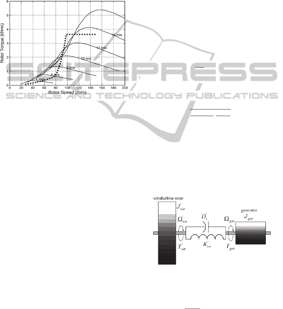
waveform for the wind turbine under consideration
is illustrated in Fig. 3. One can observe that the
dashed waveform in Fig. 3 is composed from (i) an
initial region with low incline that follows the
optimal power extraction (ii) the steep region that
limits the rotor speed up to 100 rpm and (iii) the
horizontal region where the controller takes action
and decelerates the system.
Figure 3: Proposed wind turbine rotor torque - speed
waveform.
3 MODEL DESCRIPTION
A variable speed wind turbine is generally composed
of several components, namely the wind model, the
rotor, the gearbox and the generator that are
described in this section.
3.1 Wind Model
Wind speed is calculated as an average of the fixed-
point wind speed over the whole rotor; the tower
shadow and rotational turbulences are also taken into
account. The component of main importance in this
model is the normally distributed white noise
generator. A problem that occurs when using white
noise generators is that different simulation tools use
different algorithms and thus different wind time
series are obtained. In order to overcome this
drawback, a normally distributed white noise
generator has been implemented in (Marsaglia and
Tsang, 2000);
it is based on the Ziggurat Algorithm
and uses the so-called ‘C’ S-Function.
The simulation wind model depends on the
following parameters:
Average Wind Speed: 10 m/s
Length Scale: 600 m
Wind Turbulence Intensity: 30% or 50%
3.2 Wind Turbine Rotor
The rotor is a component that extracts the energy
from the wind and converts it into mechanical
energy (Slootweg et al., 2003). The aero-turbine
model has two inputs, namely the wind speed and
pitch angle. The following parameter values have
been used to extract the internal mechanical torque.
Blade Radius: 22.5 m
Air Density: 1.25 Kg/m
3
Cut In Speed: 3 m/sec
Cut Out Speed: 25 m/sec
Besides, numerical approximations for given values
of λ and β (Ackermann, 2002)
have been used to
calculate the power coefficient C
P
. More precisely,
i
2.14
p
i
151
C λ,β = 0.73( - 0.58β - 0.002θ -
λ
-18.4/λ
-13.2)e
(4)
with
i
3
β
1
λ =
10.003
-
λ-0.002β
+1
(5)
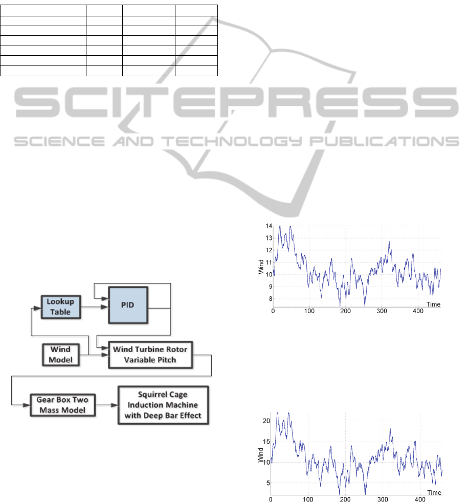
3.3 Gearbox
At this step the low angular speed produced by the
wind turbine rotor is converted into high speed in
order to reach the generator nominal values (Iov et
al., 2004). The gearbox is a two-mass model as
shown in Fig. 4. Let T
wtr
and T
gen
be the
corresponding rotor and generator torques.
Figure 4: Two-mass gearbox.
The dynamic equations of the drive-train written on
the generator side are
wtr
wtr wtr e wtr gen
wtr gen
se
dΩ
T=J +DΩ - Ω
dt
+k θ - θ
(6)
PitchControlforVariableSpeedWindTurbines
45

wtr
wtr
=
dθ
Ω
dt
(7)
gen
gen gen e gen wtr
-
se gen wtr
dΩ
-T = J + D Ω - Ω
dt
+k θθ
(8)
gen
gen
=
dθ
Ω
dt
(9)
where the equivalent stiffness is given by
wtr
gense
2
gear
11 1
=
k
kk
k
+
(10)
and the equivalent moment of inertia for the rotor is
wtr wtr
2
gear
1
JJ
k
(11)
where
Moment of inertia (Electric Machine Side): J
gen
=
90 kg*m
2
Moment of inertia (Turbine Rotor Side): J
wtr
=
49.5*10
5
kg*m
2
Shaft Stiffness: k
se
= 114*10
6
N*m/rad
Damping Coefficient of Shaft:
D
e
= 755.658*10
3
N*m*sec/rad
Gearbox Ratio: 83.531
3.4 Generator
The generator of the wind turbine under
consideration is a squirrel cage induction machine
with deep bar effect (Boukhezzara et al., 2007). The
generator has two inputs, namely the angular
velocity from the gearbox Ω
gen
and an amount of
voltage from the electric network required to start
working. The nominal value of the generator
extracted power is 2 MW.
The parameters of the generator are:
Rated Voltage per Phase: 960 Volts
Rated Current per Phase: 1310 A
Base Frequency: 50 Hz
Number of Polar pairs: 2
Starting Current: 8.8 A
Phase angle at Standstill: 79.5 deg.
Stator Resistance: 0.005 Ohm
Stator self-induction: 4.074*10
-4
H
Rotor Resistance: 0.0089 Ohm
Rotor Self-Induction: 2.992*10
-4
H
4 PID CONTROLLER DESIGN
The controller design of a wind turbine requires
determining the physical quantities to be taken into
account i.e. wind speed, mechanical torque of the
rotor, angular speed of the machine and the amount
of extracted power. In our approach the extracted
power has to converge to its set point. Besides, the
fact that the wind speed is of crucial importance to
the wind turbine operation makes the controller
construction quite difficult, since wind speed is a
non-linear variable transferred into the system. Thus,
the controller should take into account the wind
speed and continuously adjust the blades such that
the stability of the wind turbine system is
guaranteed.
PID control is one of the most popular methods
in controlling systems as wind turbines. Such
controllers are developed either independently or as
a combination with other methods (Ebrahim et al.,
2010). Recall that the transfer function of the PID
controller has the form
K
G(s)=K +K s+
s
I
cPD
(12)
where K
P
, K
D
and K
I
denote the proportional,
derivative and integral gains to be determined during
the design procedure.
4.1 PID Controller Tuning
There is no standard algorithm for tuning of the PID
controller parameters (Hara et al., 2006). The most
popular of the proposed experimental methods is the
well known Ziegler – Nichols rule (Ziegler et al.,
1942). It is performed by first setting the integral
and derivative gains to zero. Then, the proportional
gain K
P
is increased (starting at zero) until it reaches
the ultimate value K
u
for which the output of the
control loop oscillates with a constant amplitude.
The value K
u
and the oscillation period T
u
are used
to set the PID controller gains, for a specific type of
controller, according to Tab. 1.
For the wind turbine model described in Section
3 it was found that K
u
= 3.33 and T
u
= 2.65sec.
According to Tab.1, the values of the PID gains are:
K
P
= 2, K
I
= 1.51 and K
D
= 0.66. Since the above
method is an experimental one, the gain values can
ICINCO2013-10thInternationalConferenceonInformaticsinControl,AutomationandRobotics
46
be further improved for the system under
consideration. Improved gain values should lead to
more accurate closed-loop performances and, in
some sense, “optimize” the control action. Since in
this procedure it is not possible to keep constant two
of the gains and adjust the third one, one needs to
find a combination of adjustments in order to
achieve the “optimal” tuning.
Table 1: Ziegler - Nichols method.
Control Type K
P
K
I
K
D
P K
u
/2 - -
PI K
u
/2.2 1.2K
p
/T
u
-
Classic PID 0.6K
u
2K
p
/T
u
K
p
T
u
/8
Pessen Integral Rule 0.7K
u
2.5K
p
/T
u
0.15K
p
/8
Some overshoot 0.33K
u
2K
p
/T
u
K
p
T
u
/3
No Overshoot 0.2K
u
2K
p
/T
u
K
p
T
u
/3
In the light of the above observations, the
system’s operation has been tested with gain value
sets obtained from the “optimal” tuning. More
precisely, the gain values have been adjusted by
considering that the wind model follows the same
wind curve. It has been found that for K
P
=2, K
I
=
0.01 and K
D
= 2 the power extraction curve was
converging tightly to its reference value.
4.2 Controller Description
The block diagram of the closed-loop system is
given in Fig. 5. The look-up table and PID controller
blocks are created for the control design of the wind
turbine.
Figure 5: Wind turbine simulation model.
The look-up table block is used to determine the
appropriate pitch angles with input the real-time
wind value as described in Section 2.2.
The PID controller block contains the blocks
necessary to create the controller resulting from the
gain value tuning of Section 4.1.
5 SIMULATION RESULTS
The wind turbine under consideration has been
simulated in the Matlab
®
Simulink programming
environment using the Wind Turbine Blockset
(WTB) Toolbox (Iov et al., 2004). For the
simulation purposes, the PID controller design
proposed in Section 4.1 has been compared with (i)
the PID controller resulting according to the Ziegler
– Nichols rules and
(ii) the one proposed in the
literature and called from here on “initial PID”.
More precisely, in (Abbas and Abdulsada, 2010)
a
PID controller has been designed by using the
rotational speed to control the wind turbine
performance. In order to assess the controller
performance, the root mean square error between the
actual rotational speed and the desired one indicated
the capability of the controller to reject the wind
speed fluctuations. The PID controller parameters
tuned according this approach were: K
P
= 15, K
i
=
20 and K
d
= 0.1.
5.1 Wind Waveforms
The performance of the three abovementioned
controllers has been tested for both, normal and
extreme wind conditions. First, a normal wind was
considered as in Fig. 6.
Figure 6: Normal wind waveform.
It was assumed to vary in the range [7m/s –
15m/s]; its turbulence was similar to real-time wind
fluctuation values. A second group of simulations
were obtained for an extreme wind scenario as
shown in Fig. 7.
Figure 7: Extreme wind waveform.
PitchControlforVariableSpeedWindTurbines
47
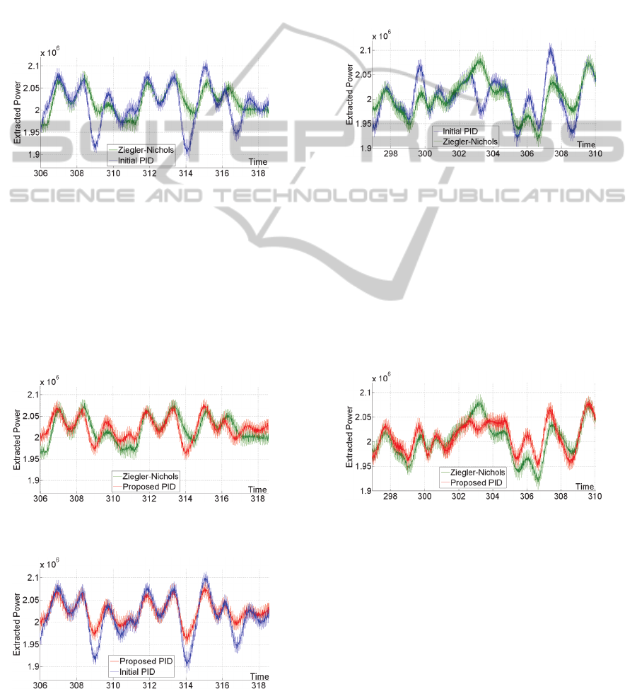
Wind speed values vary into the range [2m/s –
22m/s] and are characterized by high turbulence. It
should be noted that such a wind waveform is rarely
encountered in nature.
5.2 Normal Wind Case
Let us first compare the closed-loop system
performances obtained by applying (i) the PID
controller resulting from the Ziegler – Nichols rules
and (ii) the initial PID controller. Simulations are
given in Fig. 8.
Figure 8: Ziegler - Nichols / Initial PID controller
behaviour in normal wind conditions.
It is clear that in this situation the Ziegler –
Nichols controller waveform converges more tightly
to the set point. It should be noted that small
deviations between curves are in fact very important,
since the extracted power is measured in MW.
In the sequel, one can see that closed-loop
behavior is further improved by the PID controller
tuning of the proposed method, Fig. 9.
Figure 9: Ziegler - Nichols / Proposed PID controller
behaviour in normal wind conditions.
Figure 10: Proposed PID controller / Initial PID controller
behaviour in normal wind conditions.
Finally, simulations of the proposed PID
controller and the initial one are compared in Fig.
10. An improved convergence is obtained by the
proposed method.
5.3 Extreme Wind Case
Analogous performances were obtained in the case
of extreme wind conditions. The initial PID vs
Ziegler – Nichols controller performances are given
in Fig. 11.
Figure 11: Ziegler - Nichols / Initial PID controller
behaviour in extreme wind conditions.
Since in this case the wind turbulence is
significantly higher, the distance of the two
waveforms is clearly larger. However, it is to be
noted that the Ziegler – Nichols PID ensures a better
convergence to the set point; moreover, in several
time steps like 307sec, 309sec the deviation is
almost avoided.
Comparison of Ziegler – Nichols and the
proposed PID controller is given in Fig. 12.
Figure 12: Ziegler - Nichols / Proposed PID controller
behaviour in extreme wind conditions.
Even for relatively high turbulence, the proposed
method ensures improved performances. Note that
the convergence in the time interval 302sec to
308sec remains better.
Finally, comparison of the proposed controller
with the initial one is given in Fig. 13. It is noted
that unnecessary fluctuations are avoided by using
the proposed PID controller. In time steps like
303sec, 304sec minimum fluctuations are produced
by using the proposed controller.
ICINCO2013-10thInternationalConferenceonInformaticsinControl,AutomationandRobotics
48
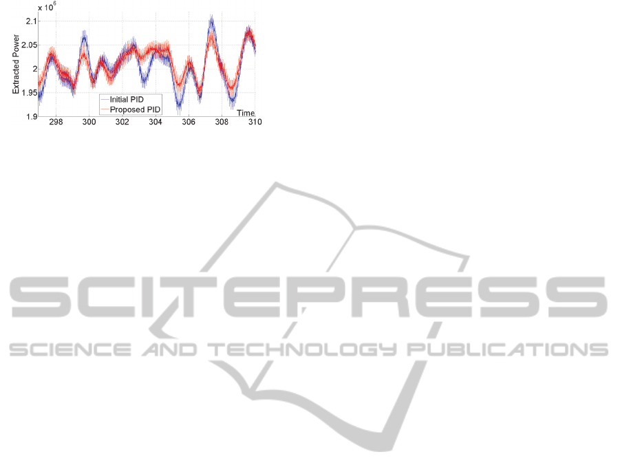
Figure 13: Proposed PID controller / Initial PID controller
behaviour in extreme wind conditions.
Furthermore, in waveform regions where
fluctuations cannot be avoided, due to the extreme
wind’s nature, the proposed controller ensures an
acceptable performance and convergence to the set
point.
6 CONCLUSIONS
In this paper, a design approach for the control of a
variable speed wind turbine system is proposed. The
extracted power has to achieve a desirable set point
of 2MW, despite wind speed fluctuations. By
appropriately adjusting the PID controller gains, the
proposed control scheme ensures the closed-loop
system’s stability and an acceptable tracking, even
under extreme wind conditions. The output
convergence to the set point has been shown to be
faster and tighter, as compared with existing PID
methods. Different control schemes for the variable
speed wind machine are presently under
investigation.
REFERENCES
Abbas F. A. R., Abdulsada M. A., 2010. Simulation of
Wind-Turbine Speed Control by MATLAB,
International Journal of Computer and Electrical
Engineering
, Vol. 2, No. 5.
Ackermann T., 2002. Transmission systems for offshore
wind farms,
IEEE Power Engineering Review.
Ackermann T., 2005.
Wind Power in Power Systems, John
Wiley & Sons, Ltd.
Asharif F., Tamaki S., Nagado T., Nagtata T., Asharif M.
R., 2011.
Analysis of Non-linear Adaptive Friction
and Pitch Angle Control of Small-Scaled Wind
Turbine System, Springer-Verlag, Berlin Heidelberg.
Boukhezzara B., Lupua L., Siguerdidjanea H., Handb M.,
2007. Multivariable control strategy for variable
speed,
Renewable Energy, Vol. 32.
Dunney F., Y. Paoz L. Y., Wrightx A. D., Jonkman B.,
Neil Kelle N., 2010. Combining standard feedback
controllers with feed forward blade pitch control for
load mitigation in wind turbines,
Proceedings of the
48th AIAA aerospace sciences meeting
, Orlando.
Ebrahim M. A., Metwally A. E., Bendary F., Mansour W.
M., Ramadan H. S., Ortega R. and Romero J., 2010.
Optimization of Proportional-Integral-Differential
Controller for Wind Power Plant Using Particle
Swarm Optimization Technique,
IJETSE International
Journal of Emerging Technologies in Sciences and
Engineering, Vol.2, No.2.
Geyler M., Caselitz P., 2007. Individual blade pitch
control design for load reduction on large wind
turbines,
Proceedings of the European Wind Energy
Conference,
Milan, Italy.
Hansen M. O. L., 2008.
Aerodymanics of Wind Turbines,
Second Edition, Earthscan.
Hara S., Iwasaki T., and Shiokata D., 2006. Robust PID
Control Using Generalized KYP Synthesis
, IEEE
CONTROL SYSTEMS MAGAZINE
.
Iov F., Hansen A. D., Sørensen P., Blaabjerg F., 2004.
Wind Turbine Blockset in Matlab/Simulink, General
Overview and Description of the Models,
Institute of
Energy Technology,
Aalborg University.
Jonkman J. M., 2007.
Dynamics modeling and loads
analysis of an offshore floating wind turbine
,
Technical report.
Leinhos D. C., Scheidler S. G., Fottner L., 2002.
Experiments in Active Stall Control of a Twin-Spool
Turbofan Engine
, Proceedings of ASME TURBO
EXPO
, Amsterdam, The Netherlands.
Marsaglia G., Tsang W.W., 2000. The ziggurat method for
generating random variables,
Journal of Statistical
Software
, Vol. 5, No. 8. (5)
Munteanu I., Bractu A. I., Cutululis N. A., Ceanga E.,
2008. Optimal Control of Wind Energy Systems,
Towards a Global Approach, Springer
Slootweg J. G.
, Haan S. W. H., Polinder H., Kling W.
L.
,2003. General Model for Representing Variable
Speed Wind Turbines in Power System Dynamics
Simulations, IEEE TRANSACTIONS ON POWER
SYSTEMS, Vol. 18, No. 1.
Strazisar A. J., Bright M. M., 2004. Compressor Stall
Control Through Endwall Recirculation
, Proceedings
of ASME Turbo Expo Power for Land
, Sea, and Air,
Vienna, Austria.
Wilson D. G., Berg D. E., Resor B. R., Barone M. F., Berg
J. C., 2009. Combined individual pitch control and
active aerodynamic load controller investigation for
the 5MW upwind turbine,
AWEA WINDPOWER 2009
Conference and Exhibition
, Chicago.
Ziegler J. G., Nichols N. B., Rochester N. Y., 1942.
Optimum Settings for Automatic Controllers
,
Transactions of the A.S.M.E.
Zhang J, Cheng M., Chen Z., Fu X., 2008. Pitch Angle
Control for Variable Speed Wind Turbine,
DRPT2008,
Nanjing China.
PitchControlforVariableSpeedWindTurbines
49
