
EASI! Enterprise Architecture for Seamless Integration
Bruno Traverson
EDF R&D,1 avenue du Général de Gaulle, F-92140 Clamart, France
Keywords: Enterprise Architecture, Information System, TOGAF, Viewpoint.
Abstract: EASI (Enterprise Architecture for Seamless Integration) aims at providing a pragmatic walk in TOGAF
(The Open Group Architecture Framework) to enable seamless integration of R&D production into
operational Information Systems. The key points of EASI adaptation are reduction to a minimal extensible
set of concepts, central focus on correspondence management and separation of publication and internal
forms of the IS Repository. EASI has been successfully used in case studies in the utility domain and
implemented in an open source modelling tool.
1 INTRODUCTION
Several Enterprise Architecture (EA) frameworks
have been defined since Zachman framework
(Zachman, 1987). All these proposals share in
common a viewpoint approach to cope with the
complexity and the layered nature of Information
Systems (IS).
In the utility domain, the integration of smart
capabilities in electrical equipments – known as the
Smartgrid – is driving the evolution of the electrical
system from a centralized hierarchical architecture
to a distributed collaborative architecture.
In this context, the complexity of the electrical
system and the complexity of the integration of
smart capabilities in the electrical system enforce the
use of adapted EA frameworks.
This paper proposes an EA framework called
EASI (Enterprise Architecture for Seamless
Integration) to cope with these complexities in a
pragmatic way. The first section describes the way
the TOGAF framework has been adapted to the
context and discusses the benefits of such an
adaptation. Then, the second section exhibits
concrete examples of application of the framework
in the Smartgrid context. Lastly, a third section
compares our approach with other frameworks.
2 FROM TOGAF TO EASI
TOGAF (The Open Group Architecture Framework)
is becoming the leading standard in the domain of
EA frameworks (The Open Group, 2011).
Because it has been designed to be agnostic to
methodologies and modelling languages, TOGAF
allows and encourages adaptation to specific
contexts.
Thus, EASI is based on TOGAF and, more
specifically, on the Architecture Development
Method (ADM) which constitutes the heart of
TOGAF.
Section 2.1 summarizes TOGAF and ADM.
Then, section 2.2 introduces EASI adaptations.
Lastly, section 2.3 discusses the benefits we
anticipate of these adaptations in the context of the
Smartgrid.
2.1 TOGAF
TOGAF is usually introduced by the following
figure (see figure 1) exhibiting ten phases involved
in an iterative lifecycle process. ADM covers phases
B, C and D.
We will detail only phases relevant to the scope
of this paper.
The “Requirements Management” phase is put in
a central place because requirements are used as
input and output of the other phases.
The “Architecture Vision” phase permits to
define the scope, the stakeholders and the objectives
of the IS project.
The “Business Architecture” phase elaborates the
business aspects of the system: organisational units
involved, business processes, roles and actors.
231
Traverson B..
EASI! Enterprise Architecture for Seamless Integration.
DOI: 10.5220/0004410702310235
In Proceedings of the 15th International Conference on Enterprise Information Systems (ICEIS-2013), pages 231-235
ISBN: 978-989-8565-61-7
Copyright
c
2013 SCITEPRESS (Science and Technology Publications, Lda.)
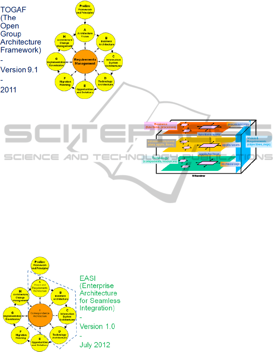
Figure 1: TOGAF 9.1.
The “Information System Architectures” phase
defines the logical view of the system into two main
categories: data and applications.
The “Technology Architecture” maps the logical
elements onto their technical implementations
(software and hardware resources).
In all these phases, activities produce various
architectural artefacts thanks to concepts that are
relevant for the nature of the activity.
In ADM phases, common activities are held:
description of the baseline architecture, description
of the target architecture, gap and impact analysis
and definition of roadmap components.
2.2 EASI
As it appears at first glance, EASI framework is very
similar to the TOGAF daisy organisation of phases
(see figure 2).
Figure 2: EASI 1.0.
However, have been applied three major
adaptations that are discussed in the next section.
Phase A called “View and Requirements
Architecture” regroups TOGAF “Requirements
Management” and “Architecture Vision” phases.
The central phase is now a “Correspondence
Architecture” in place of the “Requirements
Management” phase.
The “Information System Architectures” phase
defines the logical elements of the system into three
major sets: data, applications and flows.
Also, in these phases, core architectural artefacts
and concepts have been selected to lighten the
methodology and have been more formally defined
to lead to an implementation into a modelling tool.
All in one, these adaptations to TOGAF have
permit to organize the IS Repository as illustrated in
the following figure (see figure 3).
Figure 3: EASI IS repository.
In the Vision and Requirements Architecture, are
defined objectives, stakeholders and requirements.
Then, the Business Architecture contains business
functions and processes, the IS Architecture data,
applications and flows and the Technology
Architecture software components and hardware
resources. Lastly, the Correspondence Architecture
permits to gather traceability links like
objectives/business processes, business functions/
applications, applications/stakeholders, applications/
software components and components/objectives
relationships.
2.3 Discussion
Adaptations made in EASI framework tried to
overcome some limitations found in TOGAF – see
also (Dietz and Hoogersvorst, 2011) for an in-depth
analysis.
The fusion of TOGAF Requirements
Management and Architecture Vision phases is
motivated by the fact that scoping and objective
assignment activities are very tight to requirements
definition. The shift of the requirements
management from a central place to a peripheral
place does not mean that requirements should not be
taken into account in every architectural phase. In
ICEIS2013-15thInternationalConferenceonEnterpriseInformationSystems
232
fact, they are simply involved in a larger scope
called Correspondence Architecture as explained in
the next point.
Concerning the Correspondence Architecture
phase, our experience leads us to take as a central
preoccupation consistency between different
viewpoints. This separation also helps to move the
traceability preoccupation into a central place.
The addition of the flows set in the Information
System Architectures phase is also a key feature
because this raises the communication preoccupation
at the same level as the capitalisation of applications
and data.
The name chosen for our framework – EASI –
promises the support of seamless integration, i.e.
evolution of the Information System with no break
in the organisation and the technology solutions.
This will be illustrated in the next part on a case
study.
3 CASE STUDY
In the utility domain, Smartgrid is driving evolutions
of the - traditionally centralized and hierarchical -
architecture of the electrical system to a distributed
and collaborative one.
To better understand the value and challenges of
– for instance – introducing DER (Distributed
Energy Resources) capabilities, experimentations are
being held at the level of small regions before
generalisation to wider scales.
To facilitate the transfer of innovative solutions
found during these experimentations, EA framework
and IS repository can be used. The framework
permits to capitalize productions of the experiments
and the repository reuse in other contexts.
Some concrete challenges encountered during
these experiments will be given in section 3.1 and
the impact on tools will be addressed in section 3.2.
3.1 Challenges
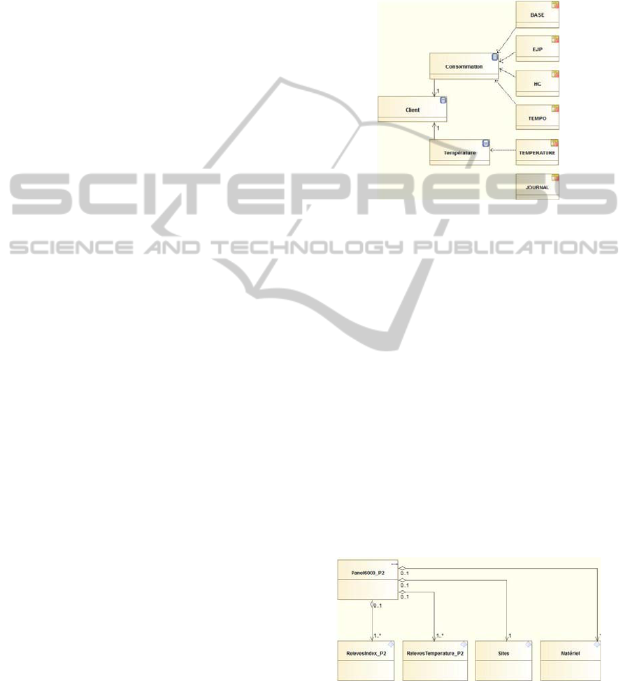
IS/Technology Correspondences - The first
example illustrates the data part of Information
System architecture and its relationship with the
technology architecture. The physical representation
of data structures may be based on a database
schema. However, this level of representation does
not permit easy communication and reuse in other
experiments. The representation in the IS
architecture gives a more conceptual view of the
data that can be shared by stakeholders.
Correspondence links permit to maintain consistency
between the two views.
Figure 4 shows the physical view of the data on
the right side, the logical view on the left side and
the correspondence links are represented by
dependency links. The signification of icons will be
given in the next section.
Figure 4: Data correspondences.
In the physical view, consumption data are stored
in separate tables when, in the logical view, one
single concept is used. In the contrary, the Client
concept appears explicitly in the logical view when
it is help using external keys in the physical view.
Lastly, some information may have no equivalent in
the other view. In the example, logging information
is pertinent only at the physical level.
Representation of Flows – The second example
illustrates the flow part of the Information System
architecture and the benefit of identifying a clear
separation between flow and message concepts. The
physical representation of messages may be based
on a XML schema description. However, it does not
capture the contents and the characteristics of the
flow(s) exchanging those messages. The
representation in the IS architecture permits to feel
these lacks as shown in the following figure (see
figure 5).
Figure 5: IS representation of messages and flows.
A flow is represented on the top of the figure and
the messages contained in the flow on the bottom of
the figure with their multiplicities. The flow is also
EASIEnterpriseArchitectureforSeamlessIntegration
233
characterized, for instance, by its frequency, its
producer and its consumer.
Publication of Models - The third example
illustrates the application part of the Information
System architecture and the publication format. The
physical representation of applications may be
characterized by Java interface elements like type of
parameters, names of operations and of interfaces.
The representation in the IS architecture permits to
keep track on characteristics like authors and
references to study notes. The publication of the
documentation on an application gathers all these
characteristics in one place.
3.2 Tooling
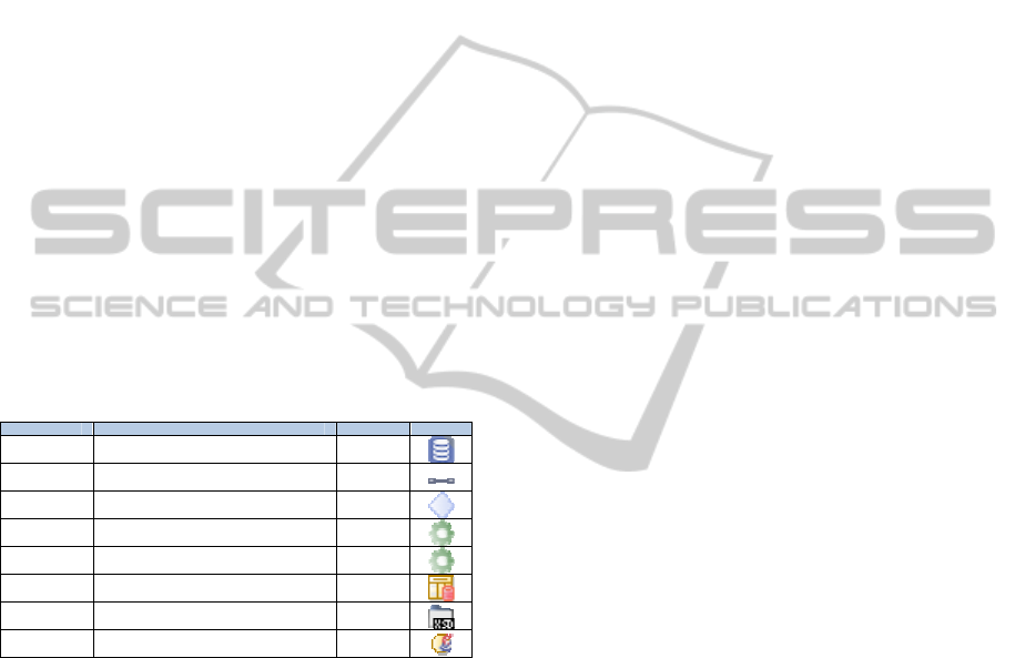
Meta-modelling – The architectural elements of the
IS Repository are implemented by UML Stereotypes
applied to the basic UML meta-elements (see
table 1). For instance, the logical view of a data
corresponds to the stereotype “IS_Data” applied to
the UML Class element. Each stereotype is
associated to a graphical representation called an
icon.
Table 1: UML profile for EASI elements.
Architecture Definition UML Icon
IS_Data Logical view of a data. Class
IS_Flow Logical view of a flow.
Information
Flow
IS_Message Logical view of a message. Class
IS_Interface Logical view of an interface. Class
IS_Operation Logical view of an operation. Operation
Table Technical view of a data as an SQL table. Class
XSDFolder Technical view of a message as an XSD schema. Class
Java Interface Technical view of an interface as a Java interface. Interface
Synchronization Models/Elements – The
synchronization between architectural elements and
their model representations is insured by
import/export modules plugged in the modelling
tool. For instance, the three bottom lines of table 1
are exact representations of their corresponding
elements. Any change in the model, respectively in
the element, will be applied to the element,
respectively to the model.
Publication – To enable separation of concerns, the
model elements of the IS Repository are clearly
separated and classified by their architectural nature.
The publication of the Repository, as explained in
the previous section on the application example,
permits to synthesize all the views of an element in
the same place. This is realized by a plug-in module
in the modelling tool.
4 DISCUSSION
Zachman - The Zachman framework combines two
dimensions. The first dimension (lines) corresponds
to levels of abstraction linked to each stakeholder
category: Planner / contextual view, Owner /
enterprise model view, Designer / system model
view, Builder / technology model view, Sub-
Contractor / detailed representation view and
Functioning Enterprise / actual system view. The
second dimension (columns) corresponds to
architectural descriptions depending on the focus:
What / data description, How / function description,
Where / network description, Who / people
description, When / time description and Why /
motivation description. This leads to a 6x6 matrix –
30 kinds of model because the last line is the
running system. The order of columns is not
significant but upper lines constrain lower lines –
like in traditional top-down approaches. Diagonal
relationships are not recommended because concepts
may have a meaning specific to a stakeholder
category and may be misinterpreted in another
category. The Zachman framework is presented as a
taxonomy to be used to evaluate an existing system
or to plan the development of a new one. Thus, it is
silent about evolution management.
RM-ODP - The Reference Model for Open
Distributed Processing (RM-ODP) recognizes five
viewpoints: Enterprise, Information, Computation,
Engineering and Technology. Identifying those
viewpoints allows the system specification to
express at the same time but distinctly the business
the IS supports (Enterprise Viewpoint), the way it is
modeled in the computer system regarding
information and functions (Information Viewpoint,
Computational Viewpoint, Engineering Viewpoint)
and the technical choices of the computer system
mapping user requirements (Engineering Viewpoint,
Technology Viewpoint). Some correspondence rules
- given in part 3 of RM-ODP standard - express
consistency constraints between two viewpoints.
However, these rules are for general-purpose and do
not designate specific instances. In other words, they
do not give to the designer the ability to navigate
through models using actual relationships between
model elements. In order to introduce navigability
between viewpoint specification models,
correspondence links (Yahiaoui, 2005) have been
introduced in the UML4ODP
specification (ISO, 2009). Navigability is an
important property for impact management.
Correspondence links permits to know what model
elements are to be checked when there is an
ICEIS2013-15thInternationalConferenceonEnterpriseInformationSystems
234
evolution.
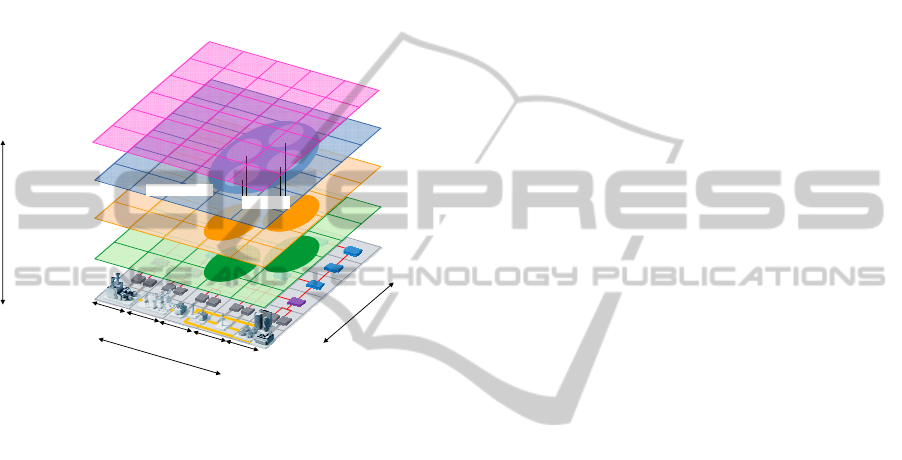
SGAM – The framework
(CEN/CENELEC/ETSI, 2011) for Smart Grid
Architecture Models (SGAM) decomposes the
system into five layers representing business
procedures, functions, information models,
communication protocols and components (see
figure 6). Each layer is comprised into domains and
zones. Domains can be arranged with the electrical
energy conversion chain and zones represent the
hierarchy of power system management.
Generation
Transmission
Distribution
DER
Customer
Premise
Process
Field
Station
Operation
Enterprise
Market
Domains
Zones
Component Layer
Communication Layer
Information Layer
Function Layer
Protocol
Protocol
Data Model
Data Model
Outline of Usecase
Subfunctions
Business Layer
Interoperability
Figure 6: Layers of SGAM framework.
This framework is interesting because it has been
proposed for the context of the Smartgrid. However,
it leads to 150 representation categories that makes it
very complex to use.
5 CONCLUSIONS
EASI framework aims at providing a pragmatic walk
in TOGAF to enable seamless integration of R&D
production into operational Information Systems in
the context of the Smartgrid.
Reduction to a minimal but extensible set of
concepts has been our first key decision in
establishing this framework. As shown in the
discussion section, other EA frameworks are much
too complex for use in rapidly evolving context such
as that of the smart grid. Another point is the central
focus on correspondence and evolution management
because our experience has shown that defining
global consistency rules and maintaining them in the
time are real challenges. Lastly, the separation of
publication and internal forms of the IS Repository
permits to handle complexity decomposition and
synthetic composition at the same time.
Arguments in favour of using EA frameworks
like EASI and implementing IS Repositories are a
better communication among stakeholders and a
broader sharing of information thanks to the
publication capability.
The price to pay is that time and money have to
be spent for consistency management and regular
publication of the IS Repository in order to
guarantee quality and accuracy of information.
Perspectives are numerous in both directions of
EA Frameworks and IS Repositories. Even if EASI
is a step forward to simplicity objective, use of such
a framework still implies some skill level.
Introduction of variability in the models and reuse of
architectural design patterns are also still challenges
for the IS Repositories.
REFERENCES
CEN/CENELEC/ETSI. Reference Architecture for the
Smart Grid, version 1.0. 2011.
Dietz, J. L. G., Hoogervorst, J. A. P., An enterprise
engineering based examination of TOGAF. EEWC
2011.
ISO. Open Distributed Processing - Reference Model Part
1-4. ISO/IEC 10746-1..4:1995.
ISO. Open Distributed Processing - Use of UML for ODP
system specifications. ISO/IEC 19793:2009.
John Zachman. A framework for Information Systems
Architecture. IBM Systems Journal, Sept. 87.
The Open Group. The Open Group Architecture
Framework, Version 9.1. 2011.
Yahiaoui, N., Traverson, B., Levy, N., 2005. A new
viewpoint for change management in RM-ODP
systems. 2nd International Workshop on ODP for
Enterprise Computing. Enschede, The Netherlands,
September 2005.
EASIEnterpriseArchitectureforSeamlessIntegration
235
