
Analyzing UML Activity and Component Diagrams
An Approach based on COSMIC Functional Size Measurement
Asma Sellami, Mariem Haoues and Hanêne Ben-Abdallah
Mir@acl Laboratory, University of Sfax, Sfax, Tunisia
Keywords: Functional Size Measurement (FSM), COSMIC - ISO/IEC 19761, UML Activity Diagram (UML-AD),
UML Component Diagram (UML-CD).
Abstract: UML is a widely used modeling language that offers a set of complementary diagram types used to describe
a system according to different views, such as the functional view, the dynamic view and the static view.
This multi-view modeling can induce inconsistencies between UML diagrams. This paper presents a
COSMIC-based approach for analyzing and checking the consistency between the activity diagram and the
component diagram. First, it elaborates a set of procedures for the COSMIC Functional Size Measurement
of each diagram. Secondly, it proposes a set of heuristics, based on the semantic relations between these two
diagrams, to assist developers in predicting the range of the FSM values of the component diagram from
those of the activity diagram. The set of measurement procedures and heuristics are illustrated through the
"Rice cooker" case study.
1 INTRODUCTION
Thanks to its various diagram types, UML provides
for a multi-view representation of user functional
requirements, system structure, and dynamic
behavior. Nonetheless, the diversity of UML
diagram types can introduce inconsistencies among
the various diagrams representing the same system.
Evidently, these inconsistencies may lead to errors,
high development costs, and potentially software
failures. Thus, it is vital to have an approach for
ensuring the consistency among the various UML
diagrams modeling the same system.
To detect inconsistencies among UML diagrams,
several approaches have been proposed either based
on meta-modeling (Chong et al., 1999), or based on
the adoption of formal methods (Sengupta and
Bhattacharya, 2008). The first category of
approaches examines only the syntactic constraints
among the UML concepts; the second category
relies on the semantic constraints among the UML
concepts and requires a certain level of expertise in
the formal method used. In addition, none of them
provides for a means both to detect potential
inconsistencies and to estimate functional size
attributes of one diagram from another already
elaborated. Such a means can be offered through a
measurement method. In this paper, we illustrate the
feasibility of such an approach by using the
functional size of software.
In the software measurement literature, to
measure the functional size of software applications,
five measurement methods have been recognized as
standards: IFPUG (ISO/IEC 20926: 2009), MKII
(ISO/IEC 20968: 2002), NESMA (ISO/IEC 24750:
2005), FiSMA (ISO/IEC 29881: 2008), and
COSMIC (ISO/IEC 19761: 2011). The main
advantage of the functional size measurement (FSM)
of COSMIC is its ability to quantify software from a
user's point of view independently of any quality and
technical criteria. In addition, compared to other
international measurement methods, COSMIC is
designed to be applicable to any type of software.
These advantages motivated several researchers to
investigate the use of COSMIC to determine the
functional size of UML-diagrams.
Current proposals to use FSM for UML focused
on particular diagrams, e.g., the use case diagram
(Sellami and Ben-Abdallah, 2009), (Lavazza and
Bianco, 2009), (Berg et al., 2005), (Azzouz and
Abran, 2004), and (Bévo et al., 1999); the sequence
diagram (Sellami and Ben-Abdallah, 2009),
(Lavazza and Bianco, 2009), (Azzouz and Abran,
2004) and (Bévo et al., 1999); the activity diagram
(Berg et al., 2005); class diagram (Sellami and Ben-
Abdallah, 2009), (Lavazza and Bianco, 2009) and
36
Sellami A., Haoues M. and Ben-Abdallah H..
Analyzing UML Activity and Component Diagrams - An Approach based on COSMIC Functional Size Measurement.
DOI: 10.5220/0004418500360044
In Proceedings of the 8th International Conference on Evaluation of Novel Approaches to Software Engineering (ENASE-2013), pages 36-44
ISBN: 978-989-8565-62-4
Copyright
c
2013 SCITEPRESS (Science and Technology Publications, Lda.)
(Bévo et al., 1999), or the component diagram (Lind,
2011) and (Lavazza and Bianco, 2009). Except for
(Sellami, 2009) and recently (Lind, 2011), these
proposals treated UML diagrams in an isolated way.
In addition, the UML-Activity Diagram (UML-AD)
has not been explored in detail, despite its
importance in representing behavioral aspects of
software. Similarly, the UML-Component Diagram
(UML-CD) has not been treated in spite of its
advantage in component reuse especially for the
development of complex applications.
This paper has a two-fold contribution. First, it
completes our previous work (Sellami, 2009) which
focused on the functional size of the UML use case
diagram as a reference measurement for the FSM of
the sequence and class diagrams. In this paper, we
use the COSMIC method to measure the functional
size of the UML-AD and UML-CD diagrams.
Secondly, it proposes a set of heuristics that provide
for both verifying the consistency of these diagrams
in terms of functional size, and estimating a bound
on the functional size of one diagram from a
developed diagram. Such an estimate can be used
for instance in a time/effort evaluation process.
The remainder of this paper is organized as
follows: Section 2 presents an overview of the
COSMIC method and existing proposals for
COSMIC FSM of UML diagrams. Section 3 and 4
present, respectively, the proposed measurement
procedure required for measuring the functional size
of UML-AD and UML-CD with the proposed
heuristics. Section 5 illustrates the application of
these measurement procedures by using the "Rice
Cooker" case study (COSMIC Group, 2008).
Finally, Section 6 summarizes the presented work
and outlines some further works.
2 RELATED WORKS
2.1 Overview of COSMIC FSM
COSMIC has been widely used in order to measure
software functional size, which is derived by
quantifying the Functional User Requirements
(FUR) (ISO/IEC 14143-1: 2007). FUR is a sub-set
of the user requirements, that explains what the
software must do to satisfy user needs. COSMIC is
developed to overcome limitations of initial FSM
methods such as Function Point Analysis. It is
designed to be used to measure functional size of
real-time software, business application software,
etc. It has been accepted as an international standard
ISO/IEC 19761 since 2003. The COSMIC
measurement procedure includes three phases:
measurement strategy, mapping, and the
measurement.
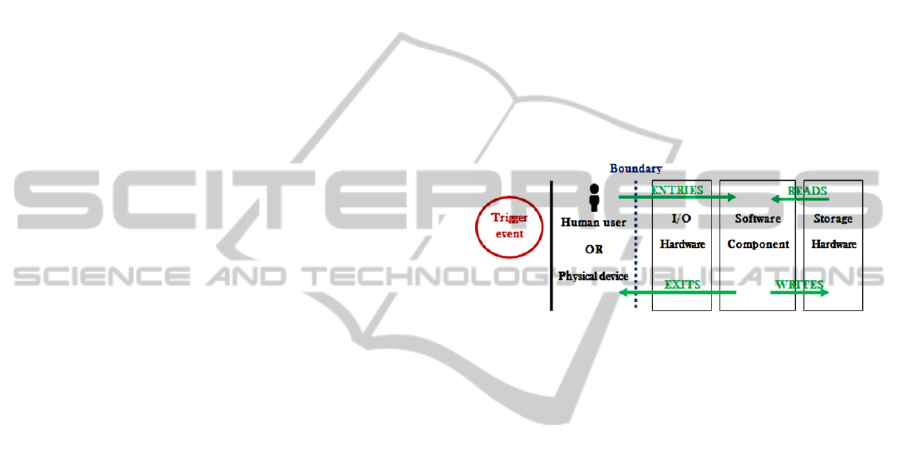
As illustrated in Figure 1, COSMIC covers four
types of data movements (Entry, Exit, Read, and
Write). The exchange of data across the boundary
between users and software components causes an
Entry data movement type (E: from a functional user
to the functional process), or an Exit data movement
type (X: from a functional process to the functional
user). On the other hand, the exchange of data
between storage hardware and software component
causes a Read data movement type (R: from a
persistent storage to the functional process), or a
Write data movement type (W: from a functional
process to the persistent storage).
Figure 1: Different data movement types in COSMIC.
In the COSMIC measurement phase, every data
movement is assigned to 1 CFP (Cosmic Function
Point). The software functional size is computed by
adding all data movements identified for every
functional process (ISO/IEC 19761: 2011)
.
2.2 COSMIC for UML
Among the researchers that studied the use of
COSMIC
to measure the functional size of UML,
(Bévo et al., 1999) investigated the mapping
between concepts of COSMIC 2.0 and those of
UML 1.0. Their investigation was presented through
the FSM of a building access system modeled with
the use case, sequence and class diagrams. Being
presented through an example, it lacked the
coverage of some concepts like the triggering event
which enduces one CFP. This study reports the issue
of identifying the appropriate UML concepts to
represent the COSMIC functional process, and then
identifying the appropriate level of granularity.
(Azzouz and Abran, 2004) also treated the UML
use case, sequence and class diagrams. They
proposed an automated functional size measurement
procedure of these diagrams when developed
according to the Rational Unified Process. Their
tool, COSMIC-RUP, is integrated in Rational Rose.
It was used to measure the functional size of two
AnalyzingUMLActivityandComponentDiagrams-AnApproachbasedonCOSMICFunctionalSizeMeasurement
37

case studies "Rice Cooker" and "Valve Control".
However, the results obtained by COSMIC-RUP
differ by 1 CFP from those obtained by a manual
measurement for each case study. Furthermore, the
proposed measurement procedure does not account
for the COSMIC “system layers” concept which is
important to identify the functional processes of a
system under measurement.
On the other hand, (Berg et al., 2005) showed
that UML can be used to present FUR at four levels
of refinement: Goal-level requirements, Domain-
level requirements, Product-level requirements,
Design-level requirements. In every level, they
assume that particular UML diagrams are used to
model the software. In addition, (Berg et al., 2005)
also showed that the functional size can be
determined using measurement methods such as
Function Point Analysis (FPA) and COSMIC-Full
Function Points (COSMIC-FFP) in the third level. In
this level, they used the use case diagram, activity
diagram and class diagram. The proposed
measurement approach is illustrated through a case
study "The Hotel Case". Despite being the only
study treating UML-AD to model the behavioral
view of software, the provided measurement
approach did not investiage several details of UML-
AD.
(Lavazza and Bianco, 2009) studied the
functional size measurement of the UML use case,
sequence, and component diagrams by using
COSMIC. Similar to the previous works, their
measurement process relies on a mapping of the
COSMIC concepts onto the UML diagram concepts.
It was illustrated through the FSM of the "Rice
Cooker" real time software. However, the UML-AD
of the "Rice Cooker" was not measured despite its
usefulness in representing system details and
interactions between the system and its actors.
Unlike the above works, (Sellami and Ben-
Abdallah, 2009) considered that the semantic links
among the various UML diagrams of a system
model must be respected in any measurement
process. First, they presented an approach to
measure the functional size of the UML use case
diagrams. Then, they propose to use the functional
size of the use case diagram as a reference
measurement for the sequence and class diagrams.
To overcome the high level of abstraction of the use
case diagrams, the authors used an intuitive
documentation of the use cases proposed by (Ali
and Abdallah, 2006). The produced measurement
can thus be used to verify the consistency of the the
use case diagram with the the functional size of the
sequence diagrams. The proposed approach was
verified using a business application "ALLOC"
(Gabay and Gabay, 2008).
Also exploring the semantic links among UML
diagrams, (Lind et al., 2011) developed a tool
"CompSize" to provide the functional size of the
component diagram (UML-CD). For this, they
extended UML-CD to represent necessary
information. However, their measurement process
defines data movements independently of the
software boundary, which may lead to incorrect
results.
In summary, as shown in Table 1, most of the
researches proposed mappings between COSMIC
concepts and some UML diagrams. None of these
studies considered all COSMIC concepts. In
addition, further work is needed to explore the
semantic links among UML diagrams types to
provide for a confrontation/estimation/consistency
verification among the different diagrams modeling
a given system.
Table 1: Summary of the proposals mapping COSMIC on UML.
COSMIC concepts (Lind,
2011)
(Sellami,
2009)
(Lavazza,
2009)
(Berg,
2005)
(Azzouz,
2004)
(Bévo, 1999)
Application border
boundary
Component Use Cases
Sequence
Use Cases
Component
Use Cases Use Cases Use Cases
System layers Component None None None None None
Functional User Component Use Cases
Sequence
Use Cases
Component
Use Cases Use Cases Use Cases
Triggering event None Use Cases Component Activity Sequence Scenario
Data group
None None Component
Class
Class Class Class
Data attribute None None None None Class Class
Functional Process
Component Use Cases
Sequence
Sequence
Use Cases
Activity Use Cases Use Cases
Data Movement
Component Use Cases
Sequence
Class
Sequence Activity Sequence None
ENASE2013-8thInternationalConferenceonEvaluationofNovelSoftwareApproachestoSoftwareEngineering
38

3 MEASURING UML-AD
3.1 Modeling Rules
To model an UML-AD that can be measured using
COSMIC, we propose 12 modeling rules. These
rules are inspired from “good design practices” and
are intended to eliminate certain inconstancies.
Modeling rules are defined to make the application
of COSMIC concepts easier. The first three rules
(R1, R2 and R3) are required at the functional level
whereas the remaining rules (R4 to R12) are used at
the dynamic level.
R1: Represent all system processes and the
relationship between them at the functional-
level.
R2: Any component or user that interacts in the
realization of a process is considered as an actor
in the UML-AD.
R3: If the activity requires incoming information or
a condition that must be satisfied, it is
considered as a pre-condition.
R4: Each functional process will be represented by
an activity diagram.
R5: Each external actor (system user) is represented
by a partition.
R6: Any internal actor is represented by a partition.
R7: All actions performed by the same actor are
grouped in the same partition.
R8: Any action requires retrieved or written data
from/to a persistent storage; it must be
associated to an object node that contains the
data to be used.
R9: Avoid the transitions between the actors and the
system when they are
intended to indicate a
possible end of the functional process (failure
or success).
R10: Every guard condition is considered as a trigger
event of its corresponding action.
R11: Action data recovery and action of writing data
are differentiated by the direction of the
transition.
R12: If the action requires incoming information that
must be satisfied, it is considered as a pre-
condition.
Note that it is required to distinguish between
external actor's partition and system’s partition
(internal actor). This distinction can be indicated by
a description of the actor's attribute.
3.2 Mapping COSMIC on UML-AD
Measuring the functional size of an UML-AD
needs to define the mapping between the COSMIC
concepts and those of UML-AD. As listed in Table
2, the mapping deals with the identification of
functional users, boundary, functional processes, etc.
Table 2: Mapping of COSMIC on UML-AD.
COSMIC
V.3.0.1
UML-AD concepts
Functional
User
Actor who interacts with the system
Boundary Conceptual line between the system
partition and actor partition
Functional
Process
An executable activity node
presented in the first level
Triggering
Event
Pre-condition of an activity
Guard condition in a decision or a
fusion node
Pre-condition of an action
Persistent
Storage
Object node: Storage
Transient data
group
Object node: Pins
Entry An incoming data (from actor
partition to system partition)
Exit An outgoing data (from system
partition to actor partition)
Read Read access from an object node
Write Write access to an object node
3.3 FSM Measurement Formulas
At the functional level, an UML-AD A consists of a
set of activities. Each activity is a functional process.
Thus
n
i
i
aFSMAFSM
1
)()(
(1)
where:
FSM (A): functional size of the UML-AD A.
n: the number of activities in A (1
st
level).
FSM (a
i
): functional size of the activity a
i
(2
nd
level).
At the dynamic level, an activity a
i
consists of a
set of actions act
ij
. According to (Knieke et al.,
2008) in this level, an activity is made by at least
one action, an end node, and an initial node.
Thus, the functional size of an activity a
i
is given by:
m
j
ij
ii
actFSM
aFSMcondaFSM
1
)(
)Precond()(
(2)
where:
FSM (a
i
): functional size of the activity a
i
.
AnalyzingUMLActivityandComponentDiagrams-AnApproachbasedonCOSMICFunctionalSizeMeasurement
39

m: is the number of actions act
ij
of the activity a
i
(2
nd
level).
FSM (act
ij
): functional size of the action act
ij
of
the activity a
i
(2
nd
level). (3).
FSMcond (Precond a
i
): functional size of the pre-
condition of the activity a
i
. (4).
The functional size of an action act
ij
is given by:
)(
) Precond()(
ij
ijij
actParamFSMparam
actFSMcondactFSM
(3)
where:
otherwise 0
condition-erp1
)Precond(
ahasactifCFP
tcaFSMcond
ij
ij
(4)
otherwise
parameter
s
outputinputhasactifCFP
actParamFSMparam
ij
ij
0
/1
)(
(5)
If an action is preceded by a decision or a fusion
node, then the guard condition is considered as a
trigger event. It is necessary to add 1 CFP to action's
size.
otherwise
conditionguardahasactifCFP
CondgardeFSMcond
ij
0
1
)(
(6)
When the end of an action in an Actor partition
causes the execution of an action in a System
partition, then the control flow corresponds to an
Entry data movement. However, if the end of an
action in a System partition causes the execution of
an action in an Actor partition, then the control flow
corresponds to an Exit data movement. Hence,
otherwise
actionsofcaseparticular
thetoscorrespondactTyptheifCFP
actTyp
F
SMactTyp
0
1
)(
(7)
4 MEASURING UML-CD
4.1 Mapping COSMIC on UML-CD
Establishing a mapping between the COSMIC
concepts and those of UML-CD is needed to
facilitate the measurement of the UML-CD
functional size. Our mapping is inspired from the
proposition of (Lavazza, 2009). Table 3 shows the
mapping between concepts of COSMIC and those of
UML-CD.
Table 3: Mapping of COSMIC on UML-CD.
COSMIC UML-CD concepts
Functional
User
External entity directly connected with the
system components
Boundary Frontier between external components and
system components
Functional
Process
Operation in a system interface invoked
directly by an external entity
Triggering
Event
Classes: physical components
Persistent
Storage
Data across the system boundary,
interface's operations or parameter's
operations
Transient data
group
Set of operations, in one or more interfaces,
carrying out a process
Entry Operations in a required interface directly
connected to the system
Exit Operations in a provided interface directly
connected to the system
Read Get type operation in a system component
Write Set type operation in a system component
4.2 FSM Measurement Formulas
Data movements in an UML-CD are represented by
interface's operations across the boundary, and
operations in a system component. The functional
size of the UML-CD (C) is given by:
)()()(
11
m
j
j
n
i
i
IFSMSFSMCFSM
(8)
where:
FSM (C): functional size of the UML-CD (C).
FSM (S
i
): functional size of operations in a system
component.
n: number of the system components.
FSM (Ij): functional size of required and provided
interfaces.
m: number of the interfaces required and provided
in (C).
The functional size of operations in a system
component is given by:
)()(
1
y
j
ijopi
OpFSMSFSM
(9)
where:
FSM (S
i
): functional size of operations in a system
component.
ENASE2013-8thInternationalConferenceonEvaluationofNovelSoftwareApproachestoSoftwareEngineering
40
y: number of operations in a component system.
(i=1,...n)
FSMop (Op
ij
): functional size of the operation
Op
ij
. (1CFP)
The functional size of required and provided
interfaces is given by:
z
k
jkj
OpFSMopIFSM
1
)()(
(10)
where:
FSM (I
j
): functional size of required and provided
interfaces.
z: number of operations in the interface I
j
.
(j=1,...m)
FSMop (Op
jk
): functional size of the operation
Op
jk
.
4.3 Correspondence between UML-AD
and UML-CD
Equation (11) can be used to verify the conformity
between an UML-AD A and an
UML-CD C in terms of COSMIC FSM:
)()(2 AFSMCFSM
(11)
The UML-AD is composed of at least one actor and
a system, an initial node, an end node, and a set of
actions. In the second level of abstraction, a UML-
AD represents a functional process. Based on
COSMIC concepts, a functional process is
composed of two data movement (Entry and Exit or
Write). Therefore, the FSM of a UML-AD is at least
equal to 2 CFP, i.e. (FSM (A) ≥ 2 CFP). On the
other hand, the FSM of an UML-CD is always less
than the FSM of an UML-AD. Hence, FSM of an
UML-CD is at least equal to 2 CFP. The maximum
size of an UML-CD depends on the size of the
UML-AD.
Equation (11) gives a confrontation means of
both diagrams in terms of COSMIC FSM. Besides
this high-level FSM boundary confrontation, we
propose the following five heuristics to ensure the
consistency in terms of COSMIC FSM between
UML-AD and UML-CD:
ConsR1: Any partition representing an actor in
UML-AD is a component in the UML-CD.
ConsR2: Any action in a partition is represented
by a method in an interface.
ConsR3: Input/output pins in the UML-AD
correspond to the input/output parameter's
operations in the UML-CD.
ConsR4: Object nodes in UML-AD are
represented by class’s components in UML-CD.
ConsR5: Pre and post-conditions of an action in
UML-AD correspond to pre and post-conditions of
an operation in UML-CD.
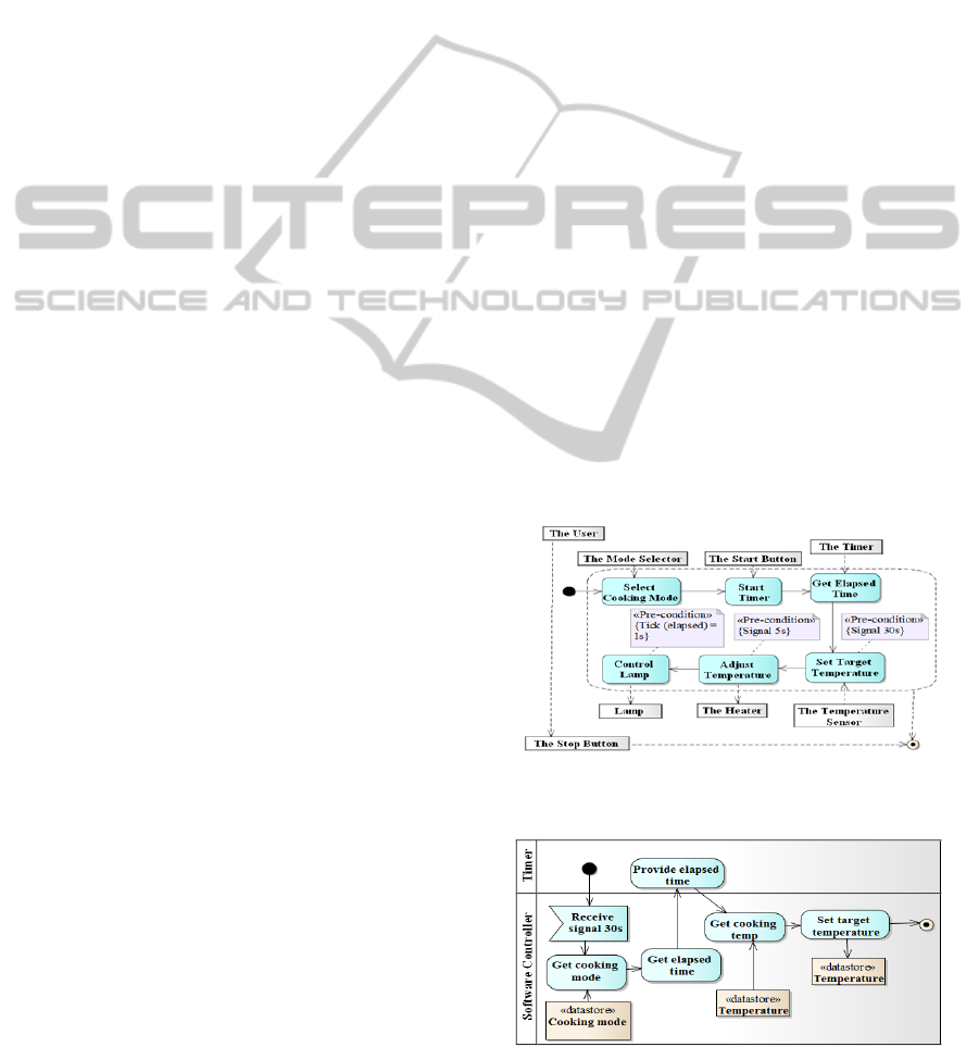
5 EXAMPLE: THE RICE
COOKER
To illustrate the application of the proposed FSM
formula, we use the real time software application
"Rice Cooker" case study. The FURs of this case
study are described in (COSMIC Group, 2008). The
question is how to determine the functional size of
the three functional processes (FP1: Set Target
Temperature, FP2: Adjust Temperature and FP3:
Lamp Control) as described in (COSMIC Group,
2008). These processes are triggered by three events
which are respectively:
Signal 30s: Every 30s software controller selects a
new target temperature.
Signal 5s: Every 5s software controller must
compare between the target temperature and actual
temperature to control the heater.
Tick (elapsed): Every 1s the timer must issue the
elapsed time since button START is turned on.
Figure 2 shows the activity diagram of the "Rice
Cooker" application at a high level of abstraction.
Figure 2: UML-AD of the "Rice Cooker" application (high
level of abstraction).
Figure 3: UML-AD of the "Set Target Temperature".
AnalyzingUMLActivityandComponentDiagrams-AnApproachbasedonCOSMICFunctionalSizeMeasurement
41
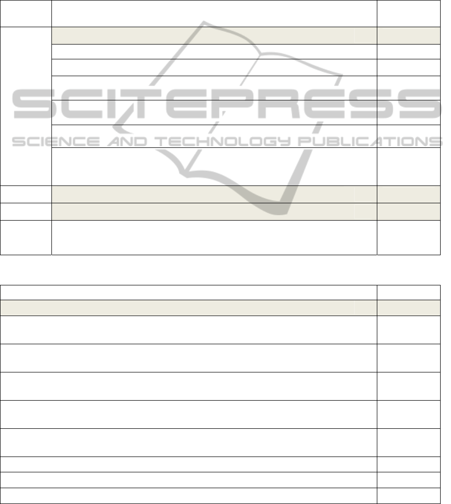
Figure 3 illustrate the UML-AD of the functional
process "Set Target Temperature".
Table 3 presents in detail the measurement
results of the UML-AD for the functional process
(FP1). Due to space limitation, we will present only
the measurement results for the two other processes
(FP2, FP3). In addition, based on the component
diagram of the "Rice Cooker" in (Lavazza and
Bianco, 2009), which includes three components and
five interfaces; we will present the FSM results of
the related UML-CD in Table 4.
According to equation (11), it can be ensured
that the UML-AD design is conformed to the
UML-CD design. In addition, assuming that the
Table 3: Measurement results (Activity diagram of the "Rice Cooker").
Functional
Process
Application of measurement formulas
(UML-AD)
Measurement
results in CFP
FP1
FSMFP1FSMcondSignal30s
∑
FSMact
(2)
6
FSMcondSignal30s
(4)
1
FSMact1jFSMcondPrecondact
FSMparamParamact
(3)
03
FSMcondPrecondact
1CFP ifact
hasapre˗condition
0 otherwise
(4)
0
FSMparam Param act
1j
=
1CFPifact
hasinput/outputparameters
0otherwise
(5)
3
FSMactTyp
actTyp
1CFP ifactTypisaparticularcase
0 otherwise
(7)
2
∑
FSMact
FSMReceivesignal30sFSMGetcookingmode
FSMGetelapsedtimeFSMProvideelapsedtimeFSMGetcookingtemp
FSMSettargettemperature
010
011
FP2
FSMFP2FSMcondSignal5s
∑
FSMact
(2)
6
FP3
FSMFP3FSMcondSignal1s
∑
FSMact
(2)
2
Total
FSM
A
FSM
a
(1)
14
Table 4 : Measurements results (UML-CD of the "Rice Cooker").
Application of measurement formulas (UML-CD) CFP
FSMC
∑
FSM
S
∑
FSMI
(8)
12
FSMS
:CookingModeC
∑
FSM
Op
FSMGetMode:Cooking_modeFSMSetModemode:Cooking_mode
(9)
11
FSMS
:CookingSpecsC
∑
FSM
Op
FSMGetCookingTemptime:
Integer,mode:Cooking_mode:Integer
(9)
1
FSMS
:CookingStateC
∑
FSM
Op
FSMSetTargetTemptemp
FSMGetTargetTemp:Integer
(9)
11
FSM
I
:TimedEvents
∑
FSM
Op
FSMSignal30s
FSMSignal5sFSMTickelapsed
(10)
111
FSM
I
:TempSensorCommands
∑
FSM
Op
FSMReadTemp:Integer
(10)
1
FSM
I
:HeaterOnInterface
∑
FSM
Op
FSMHeaterOn
(10)
1
FSM
I
:HeaterOffInterface
∑
FSM
Op
FSMHeaterOff
(10)
1
FSM
I
:LampCommands
∑
FSM
Op
FSMOn
(10)
1
ENASE2013-8thInternationalConferenceonEvaluationofNovelSoftwareApproachestoSoftwareEngineering
42

consistency heuristics are satisfied, the FSM
difference between the UML-CD (12 CFP) and the
UML-AD (14 CFP) can be justified by the
difference in the levels of abstraction. Since UML-
AD represents software at a more detailed level and
UML-CD represents software at a high-level of
abstraction, UML-CD does not represent all
software details as well as UML-AD. Looking
closely, in the UML-AD FP2, the extra CFP is due
to the guard conditions which are not represented in
the UML-CD.Table 3: Measurement results
(Activity diagram of the "Rice Cooker")
Compared to existing works, our measurement
results are consistent with those of (Lavazza and
Bianco, 2009) and they ensure the correctness of our
measurement procedures. Albeit, it can appear that
there are some distinctions in the FSM results. For
instance, we measured 14 CFP for UML-AD and 12
CFP for UML-CD of the "Rice Cooker" case study,
while the FSM of the same case study calculated by
(Lavazza and Bianco, 2009) is equal to 11 CFP.
Their value is provided according to the
identification of data movement involved in
functional processes. It is independent of the UML
diagrams. It can be observed that, for UML-AD,
there is an extra of 3 CFP for three "Exits". Because
of FP1 contains the transition "Get elapsed time", it
should be considered as a data movement type
"Exit". However, (Lavazza and Bianco, 2009)
ignored this data movement. In FP2, the extra 2 CFP
are due to: (i) the guard conditions which were not
treated by (Lavazza and Bianco, 2009) for both
actions "Start heater" and "Stop heater". They
considered the command “HeaterOn and HeaterOff”
as 1 data movement “Exit”; and (ii) the action "Get
Actual Temperature" was not identified by (Lavazza
and Bianco, 2009) since they considered the “Actual
Temperature” to be returned by “Temperature
Sensor” following the demand of “Software
Controller”.
Furthermore, for the UML-CD, the extra 1 CFP
is due to the operation
"
SetMode(mod:Cooking_mode)". Indeed, this operation
corresponds to another functional process (stop
cooking). If we take into account the ‘scope’
according to COSMIC method, this operation will
not be considered. In addition, our measuring scope
is limited by the three FP (Set Target Temperature,
Adjust Temperature and Lamp Control).
6 CONCLUSIONS
Applying COSMIC FSM method in the design phase
for checking consistency between activity diagram
(UML-AD) and components diagram (UML-CD) is
the main purpose of this paper. To meet this
purpose, functional size measurement procedures for
UML-AD and UML-CD were presented. These
procedures were defined based on the mapping
between COSMIC concepts and those of UML
diagrams concepts. We have proposed a
measurement interval that it can be used as a
guideline by designers and developers to verify
consistency between UML-AD and UML-CD and to
identify modeling errors. We have also proposed a
set of modeling rules to ensure the consistency
between those diagrams. Finally, we have illustrated
the proposed measurement procedures by using the
"Rice Cooker" case study, and confronted our
measurement results with those of (Lavazza and
Bianco, 2009).
Further works including the use of measurement
results of UML-AD and UML-CD should be
investigated. These measures can also be helpful to
software managers and leaders to complete their
project within the scheduled dates. The proposed
formulas need to be applied on larger case studies to
ensure the quality of measurement results. Finally,
implementation is also required not only to find
faster the FSM of each UML diagram, but also alert
users (developers, designers, etc.) with the presence
of any modeling errors in the design phase.
REFERENCES
Ali, M., Ben Abdallah, H., and Gargouri, F. 2006.
Validation des besoins dans les modèles UML 2.0. In
XIVème congrés INFORSID. Hammamet, Tunisia.
Azzouz, S., Abran, A., 2004. A proposed measurement
role in the Rational Unified Process (RUP) and its
implementation with ISO 19761: COSMIC-FFP. In
SMEF 2004, Rome, Italy.
Berg, K. v. d., Dekkers, T., Oudshoorn, R., 2005.
Functional size measurement applied to UML-based
user requirements. In SMEF 2005, Rome, Italy.
Bévo, V., Levesque, G., Abran, A., 1999. Application de
la méthode FFP à partir d'une spécification selon la
notation UML: In IWSM’99, Lac Supérieur, Canada.
Chong, K. W., Cho, Y.S., Know, S.G., 1999. Detecting
Errors and Checking Consistency in the Object-
Oriented Design Models. In Journal of KIPS. Korea.
COSMIC Group. Case Study: Rice Cooker. May 22, 2008.
Gabay, J., Gabay, D. UML 2 Analyse et conception: mise
en oeuvre guidée avec des études de cas. Paris:
Dunod, 2008.
Knieke, C., Huhn, M., Lochau, M., 2008. Modeling and
Validation of Executable Requirements Using Live
Activity Diagrams. In SERA'08, Prague.
AnalyzingUMLActivityandComponentDiagrams-AnApproachbasedonCOSMICFunctionalSizeMeasurement
43

Lavazza, L., Bianco, V., 2009. A Case Study in COSMIC
Functional Size Measurement: The Rice Cooker
Revisited. In IWSM '09, Amsterdam, Netherlands.
Lind, K., Heldal, R., Harutyunyan, T., Heimdahl, T., 2011.
CompSize: Automated Size Estimation of Embedded
Software Components. In IWSM 2011, Nara, Japan.
Luckson, V., Lévesque, G., 2004. Une méthode efficace
pour l’extraction des instances de concepts dans une
spécification UML aux fins de mesure de la taille
fonctionnelle de logiciels. In ICSSEA’2004, Paris.
OMG Unified Modeling Language (OMG UML). Version
2.4.1. Object Management Group. 2011.
Sellami, A., Ben-Abdallah, H., 2009. Functional Size of
Use Case Diagrams: A Fine-Grain Measurement. In
ICSEA '09, Porto, Portugal.
Sengupta, S., Bhattacharya, S., 2008. Formalisation of
UML Diagrams and Their Consistency Verification –
A Z Notation Based Approach. In Isec’08, Hyderabad,
India.
ENASE2013-8thInternationalConferenceonEvaluationofNovelSoftwareApproachestoSoftwareEngineering
44
