
Piaget for the Smart Control of Complex Robotized Applications
in Industry
H. Omori
1
, J. -D. Dessimoz
2
, H. Tomori
1
, T. Nakamura
1
and H. Osumi
1
1
Department of Precision Mechanics, Chuo University, 1-13-27 Kasuga, Bunkyo-ku, Tokyo, 112-8551, Japan
2
Institute for Industrial Automation, HEIG-VD, CH-1400, Yverdon-les-Bains, Switzerland
Keywords: Industrial Automation, Robotic Manipulator, Modularized Software, Piaget.
Abstract: The control of smart robots, and now similarly smart applications in Factory Automation require
programming and control capabilities at the integral level of many heterogeneous resources. Significant
proposals exist for this purpose, such as ROS, yet we had to develop an original solution, “Piaget”. Piaget
can be deployed at a very low level, with very fast capabilities (e.g. 100 nanosecond long time slots in
average), but more and more is concentrated on higher hierarchical levels, where it brings the capability to
flexibly coordinate multiple, largely smart and otherwise autonomous subsystems. This perfectly reflects
fundamental constraints in closed-loop control, which occurs in numerous instances for a smart system.
Piaget is especially useful in three important phases of projects: development, programming, and real-time
operation. An industrial case is studied, involving multiple, otherwise independent, commercially available
subsystems, such as industrial robot arm, PLC, IP camera or joint controller. As always, a special end-
effector, here multi-tool, had to be designed for the application. Highlight is given of selected software
items, relating to the overall application, to the robot arm, or to the vision part. Experiments are reported,
addressing three of the most significant process components. Outcomes are successful.
1 INTRODUCTION
Factory Automation (FA) produces highly variable
objects such as cars, motorbikes, TV’s, PC’s or
novel mobile phones, characterized by large as well
as small, complex and often also precise features. A
lot of components, such as actuators and sensors, are
used to conduct these production processes. And IT-
based, automatic systems play a key role here. Now
however to link all these resources in an efficient
and reliable way has been found a persisting
challenge. In particular, the latter traditionally
requires a variety of different program languages for
development and operation. Proper novel IT
technologies are searched for improvements.
Notably, Robot Technology-middleware(RTM)
(Ando et al., 2005), Microsoft Robotics Developer
Studio (MRDS) (Quigley and Jackson, 2007), Robot
Operating System (ROS) (Quigley et al., 2009),
Open Robot Interface for the Network (ORiN)
(Mizukawa et al., 2004) have been developed for
integrating robot systems on the basis of
modularized software components. The concept is
typically to allow programmers to develop programs
as individual components, with different computer
languages, and then to integrate their results. In
principle, these soft elements are easily reused for
other automated and robotic systems. The program
can run in real time. Openness, Productivity, and
Collaboration (OPC) (Son and Yi, 2010), Data
Distribution Service (DDS) (Calvo et al., 2011) have
also been developed for an industrial automation
system, with a special attention on real time aspects
of operating systems. These solutions have been
demonstrated for some application niches, but
current applications may be very varied and/or
advanced (García et al., 2012); (Liu et al., 2012);
(Maier et al., 2012); (Tsai et al., 2012). OPC and
DDS seem to provide neither the ultimate answer,
nor even the way towards it. A particular challenge
is to support overall coordination of complex
resources through the main subsequent phases of
projects and applications: development,
programming, and real-time operation.
In our work, the attempt has been made to cope
with really complex situations, e.g. like for robots
cooperating with humans in domestic tasks; or as
concretely illustrated below, for the smart control of
528
Omori H., Dessimoz J., Tomori H., Nakamura T. and Osumi H..
Piaget for the Smart Control of Complex Robotized Applications in Industry.
DOI: 10.5220/0004425405280535
In Proceedings of the 10th International Conference on Informatics in Control, Automation and Robotics (ICINCO-2013), pages 528-535
ISBN: 978-989-8565-71-6
Copyright
c
2013 SCITEPRESS (Science and Technology Publications, Lda.)
complex robotized application in industry.
Essentially, two fundamental questions have been
addressed: 1. What is cognition? 2. How to
implement (machine-based) cognition in real-world
applications? And Piaget has progressively emerged
as an appropriate IT set of answers at their crossroad.
In particular, cognition is defined as the
capability to provide the right answers in a given
domain. Most of the core ontological and metric
definitions have been provided (Dessimoz, 2012);
evidence results of the infinite complexity of reality;
consequently, a careful selection of specific goals is
found necessary, as a prerequisite for the elaboration
of tractable models.
The extraordinary variety of potential
applications of automated cognition in the real-
world calls for the contributions of the whole society,
mostly coordinated, today, by market mechanisms.
Thus Piaget has been designed with the goal to
integrate current elements of solutions in as much as
possible, far beyond team and community levels.
Metric evaluations show that microelectronics and
IT/ICT technologies allow for the largest quantities
in cognitive performance; Piaget, beyond modelling,
mostly relates to them (Dessimoz et al., 2011).
Let us now consider an industrial case, presented
here with full scientific significance even though,
some major partner-related aspects may have been
changed or are kept confidential.
From a hardware point of view in industry, a
production line is long. A machine or robot is often
in charge of a single task such as inserting a part,
tightening up a screw, monitoring a process for
productions are complex to achieve. In such cases,
production speed is often fast but requires large
facilities and investments. It is difficult to produce
different types of products in a same line. It requires
major changes of working machines and robot tools.
On the other hand, robot manipulators are widely
used in factory automation. Some can conduct
several tasks, changing multiple tools (end effectors).
However, high user skills are needed to control them
from external computers, to reconfigure them with
other peripherals (gripper, camera, sensors) and to
define a sequence of tasks using all of them.
Therefore, we focus on using a manipulator that
can operate for several representative production
processes. The Piaget environment integrates and
controls the manipulator and also provides
middleware services. Small metallic balls, glue and
two parts require the development of a prototype
automatic assembly system. Metallic balls are
extensively used in assembly (re. bearings, rotation
parts, and ball valves, glue). The manipulator has 3
different tools for picking up parts (gripper), picking
up and setting balls (vacuum), and putting the glue.
They are simple mechanisms therefore they can be
easily changed for different tasks and components.
A camera, turning table and Programmable Logic
Controllers (PLC) are required. The Piaget control
program is easily developed and changed, and may
involve the design of specific additional forms.
In this paper, we describe first Piaget and critical
control issues, along with theoretical aspects. Then
part 3 describes the representative industrial
application, including hardware, and software. Then
in part 4, we carry out experiments and document
the outcome of the whole automatic assembly
process.
2 PIAGET AND CRITICAL
CONTROL ISSUES
2.1 Piaget Main Features
Piaget is a programming and control environment,
continuously developed since 1998, with two major
classes of goals. In the first one we find real-time
and real-world capabilities, with compiled and
interpreted components, autonomous and interactive
functionalities, VAL-style robot instruction subset,
selective configuration changes and simulation
capabilities, which are key constraints in robotics
and automation; the second class of goals includes
less specific, yet also desirable objectives: modular
structure; multiple levels of ergonomics and
flexibility (interface adaptable from beginner to
expert levels); subsidiarity (don’t reinvent the
wheel); possibility of software reuse and to
distribute programs (Dessimoz et al., 2011). The
current implementation is mostly done in
C++, for various kinds of Windows OS; other
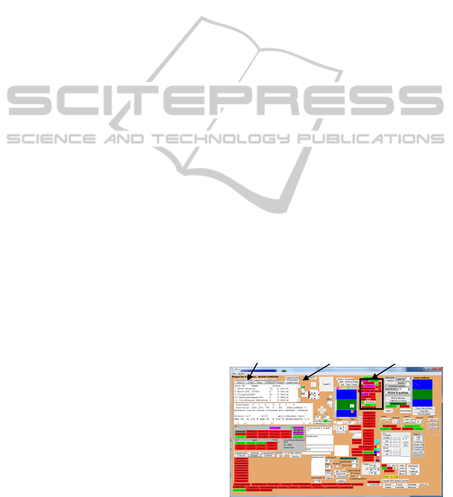
Vision window Staubli control Interface selection
Figure 1: Main control form of Piaget.
PiagetfortheSmartControlofComplexRobotizedApplicationsinIndustry
529

implementations include Pascal, C (“Piaget-light”),
and C#, under DOS, Windows, or RTDOS.
uMain.cpp
…
while (! InteractionExpected)
{Ticks+=1;
Task02(); // Move for one joint increment
Task03(); // Read keyboard
Task04(); // Point to point move (joints)
Task05(); // Strategy
Task06(); // Real-world IO
Task07(); // Update, display status form
Task08(); // Cartesian move
Task09(); // Head lightmanagement
Task10(); // Computer vision
Task11(); // Servocontrollermanagement
Task13(); // Checks if US sensor triggered
Task14(); // Communication
Task15(); // Laser ranger management
Task18(); // Piaget interpreter- Multi tasking
management
Task19(); // Voice recognition
Task20(); // Dialogue Manager
Task21(); // Map Manager}
…
Figure 2: Core structure of task management in Piaget.
In this paper, we are referring to Piaget embedded in
C++. Figure 1 shows the main control form of Piaget.
Like in the cockpit of a plane, a lot of “immediate
level” displays, key and controls allow for
information-dense and fast interaction, as well as
simple training. A lot of external resources can be
used in this program such as colour or IR Cameras,
DC motors, PLC, 2D1/2 TOF or planar ranger, robot
arms (mobile or industrial), motor controllers,
communication ports, etc. Different contexts for
them (forms) can be easily triggered by ad hoc
selection panels on the main form (or by the running
program). Typically, in time, selected interfaces are
used and controlled individually. Also, the
collaboration of several interfaces and sequences of
tasks can be carried out. This programming
environment has been used for the development and
real-time control of several home assistance robots
such as RHY, OPY, or a NAO humanoid (Dessimoz,
2010). Below, this paper describes Piaget for an
industrial application. Figure 2 shows the tasks in a
main program. The granularity of parallelism is very
fine. Each task is divided and executed as 100
nanosecond long time slices in average, with a round
of all agents completed in about 2 microseconds.
Experimental evidence shows that these time
statistics apply even though all the additional
processes managed by Microsoft Windows run
simultaneously on the same computer.
2.2 Example of Typical, Entry-level
Piaget Program
The Piaget environment can be modified in 4 main
…
735: Mute=false;
SayStringAndWaitAGN("OK. I Start");
break;case
736: MoveAGN(Trans(553,62.5,90));
break; case
737: TakeAPictureAGN();
break; case
…
2862: if (StaubliReady == true)
{PBZ = PBCZ - 10;
SignalOutAGN(6,false);
StaubliUpdateMotionPiaget(PBX, PBY, PBZ,
PBRX, PBRY, PBRZ, 10, 2);
GoNext() ; }
break; case
…
EstimateObstaclePositionByVisionRAH(L0Target.x,L0T
arget.y); //return the target
position that robot must follow
…
AcquireAndDisplayDistancesWithLaserAGN();
…
SendMessageCom("byeright");//to NAO
…
Figure 3: Selected examples of Piaget program in strategy
context. The first part involves a mobile robot in domestic
context; in the middle, the example relates to a Staubli
industrial robot; and the last line has been used in a multi-
robot application including the humanoid NAO (re.
Aldebaran Robotics). Many other instructions exist for
example for transform calculus, kinematics, vocal
recognition or map management.
ways. It can already be interactively used,
configured, parameterized just with the executable
code. Then, and this point is developed here, it can
be programmed in Piaget language within the
strategy task or agent ( Figure 3).
Other possibilities are offered at a third level
where parallel agents can be added. Finally, a 4
th
way to program involves the expert level, where in
particular Piaget is implemented in various lower
level languages and OS.
For a robot, the target in space to be reached is
crucial. Like in VAL, a “location” type is defined:
e.g. “
LocationL0Target;”. There are also instructions
and functions associated with this type: e.g.
“L0Target=Here (); SetAGN (L0Target, Here ());
L0Target=Trans (10,20,30)”.
The most relevant however
are the IO and motion instructions: e.g.
“
SignalOutAGN(5,true); MoveAGN(L0Target);”.
Piaget instructions are numbered, and the program
counter is explicitly managed; e.g. the “
AGN” suffix
means “
And Go to the Next instruction”.
2.3 Dynamic Constraints in controlled
Systems with Disturbances
In case of disturbances, which are very frequent in
real-world systems, closed-loop control is very much
required. It may be too little known that strong
dynamic constraints limit the possibilities of success
in this context. Consider the agility of a control
ICINCO2013-10thInternationalConferenceonInformaticsinControl,AutomationandRobotics
530
system Ac, and the agility of the system to be
controlled As. Agility is the inverse of response
time. A very simple model suggests that the ratio
Ar=Ac/As, should be higher than 2. If Ar is higher
than 20, a simple on-off strategy is applicable.
Although if lower than 2, additional resources are
required, leading to the concept of hierarchical
structures.
In complex applications such as considered in
this paper, with multi-agents and numerous closed-
loops, care must be taken that in all cases the
mentioned constraints are respected.
2.4 Hierarchical Robot Control,
Classical 3-level Structure,
and Piaget
It is well known that robot control can schematically
been represented as a 3-level structure: 1- robot-
operator interaction, smart sensors use and overall
“point to point” motions. Time constant is here of
the order of 1 s, and location coordinates are usually
Cartesian, with Euler angles. 2-coordination,
typically ensured along with inverse kinematics
conversions and enforcement of a specific motion
law in time. Interpolation is done to an agility about
30 times higher; time constant is of about 30 ms. 3-
joints individually controlled, with closed-loop
strategies, and time constants smaller than 1 ms.
Piaget is required to manage the complete system.
As a solution, two types of strategies are pursued.
The first type of strategies consists in implementing
very fast operations when necessary. This could be
conveniently done in the past, when systems were
smaller, communication and OS constraints were
minor. The evolution of IT however calls for a
second type of strategies, relying on “external”
resources. Out of necessity, a much larger
heterogeneity is now accepted in the various
components. Problems may arise in terms of specific
licenses and quantity of paradigms. The advantage is
however a virtually unlimited source of expertise at
global level. It is in such a rich and “bushy” context
that Piaget turns out to deploy its best merits.
Beyond the intrinsic levels of Piaget hierarchies,
additional resources can be found in two directions.
For speed in lower level, implementation languages
help, and autonomy is granted to specialized
resources: notably PLC, joint controllers,
microcontrollers, smart sensors and actuators. For
cognitive power in higher levels, e.g. voice
recognition and synthesis, dynamic 3D modelling,
control of industrial robots or humanoids at
trajectory level, additional processes may run with a
lot of autonomy as well, information being shared by
files, either stored internally on the computing
platform or exchanged through the standard
communication channels, USB or TCP-IP notably.
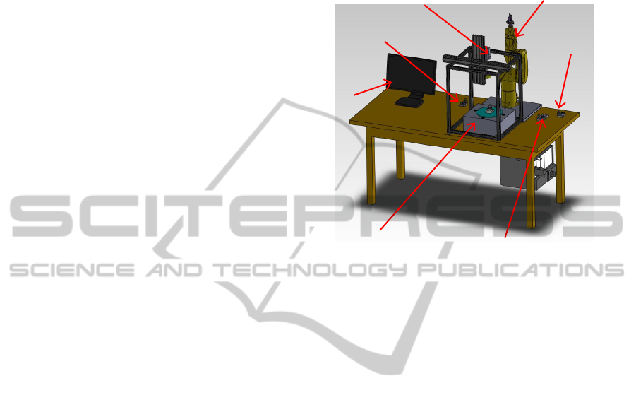
Figure 4: Design of automatic assembly system.
3 INDUSTRIAL APPLICATION
This chapter describes a test application for an
industrial purpose. We explain the system from
hardware and program points of view (Piaget).
3.1 Hardware Development
3.1.1 Overview of the System
Figure 4 shows the design of the assembly system.
Here are the manipulator (Staubli TX-40), delivered
base, working base, camera system, turning table,
end process base, and Computer (PC). PC connects
all electric components with TCP/IP. The process of
assembly can globally be described as follows. First,
a part to be assembly will be delivered near the
workspace of the manipulator by a conveyer, other
manipulator or a mobile robot in the future. In this
prototype system, the process of assembly starts
from the part being delivered and set on the
delivered base. Next the manipulator picks up the
part, transports to the work base and starts putting
glue in the holes. After that glue is checked one by
one on the turning table using the camera. Balls are
set on the holes over glue in the working base. In the
end, the camera checks balls again. The process of
assembly finishes if the glue and balls are properly
set on the holes.
Camera
PC
End process base
Staubli
Delivered base
Working base
Turning table
PiagetfortheSmartControlofComplexRobotizedApplicationsinIndustry
531
Figure 5: End effecter with three different tools.
3.1.2 End Effecter of a Manipulator
The tool on the Staubli has 3 different tools, gripper,
ball tool, and syringe (Figure. 5). The gripper is for
picking up and holding the part. The ball tool is for
dealing with a ball. It can pick up one ball using
negative pressure. The syringe is for glue. It has
elastic band for compliance because the tip of the
needle should touch the hole of the part to put the
glue. The syringe goes up when the tip of the needle
touch the hole. These three tools are controlled by
air pressure. PLC controls valves of the air pressure.
Each of them would be easily changed for changing
a specification of a part, ball and glue because of the
simple mechanism.
3.2 Software Development
3.2.1 Overview of Interactive Control
in Piaget for the Test Application
Considering interactive possibilities of operators or
development engineers, Figure 6 shows the main
control form for the industrial application. This form
is divided into 4 parts, Manipulator control, turning
table, task for assembly, glue and ball detection.
3.2.2 Manipulator Control Program
Piaget allows for the global real-time control and
software development of the overall production cell.
At the local level, for the control of Staubli
manipulator, it is the proprietary, StaubliVal3
environment that provides the adequate solution, e.g.
for accurate inverse kinematics, and key security and
error-tracking capabilities. Therefore some program
commands have been developed within Piaget scope
to communicate with Staubli, making use of TCP-IP,
Figure 6: Main control form for industrial application.
Figure 7: Communication flow chart between Piaget and
Val 3.
Ethernet based, communication standards. Figure 7
shows the flow chart of program between Piaget and
Val 3. Essentially, once the connection is done
between them, Piaget sends 3 commands to Staubli.
One is the motion command including position,
orientation, velocity and motion patterns. The others
are On/Off command for the gripper. Staubli is
waiting for a command from Piaget. If Staubli
receives a motion command, it starts moving and
sends current position and orientation every 0.1 s.
It sends “Endmove” when it reaches a desired
position and orientation to inform that it reaches
them and stopped motion. This is required because it
corporate with other tasks such as gripping, putting
glue and setting balls.
In the end, the manipulator can be controlled
manually in manipulator control (Figure. 6 in
manipulator control). The orientation shows rotation
around X, Y, and Z axes (Euler angles) as computed
Staubli(Val3),Sever PC(C++,Piaget),Slave
Runsaprogram
Runsaprogram
ConnectstoStaubliWaitingforaconnection
Getscurrentposition
Sends “currentposition”
and“EndCommand”
Waitingfor “Currentposition”and
“EndCommand”
SendsaPositionCommands,Motion
patterns,Velocity,orGripperOn/Off
Waitingfor acommand
Moves
Gripper
Syringe
Ball tool
Manipulator Control Turning Table
Task for
assembl
y
Glue and ball
detection
Results of glue and ball
ICINCO2013-10thInternationalConferenceonInformaticsinControl,AutomationandRobotics
532
inside Piaget program. Coordination system, base
coordinate and tool coordinate are also selectable.
Piaget does on its own provide the transform
utilities to allow users to specify robot motions in
the frame they find most convenient at a given time.
4 EXPERIMENTAL RESULTS
WITH TEST SYSTEM
Experiments have been conducted, according to the
task flow presented in 3.1.1. Each step was
separately programmed and conducted. Tasks were
selected on the form in Figure. 6. The experiments
have been successful. They have been documented
by videos, and, even though this was not optimized
for speed but for proof of concepts and safety in lab
environment, Table1 shows the tasks and time of
completion.
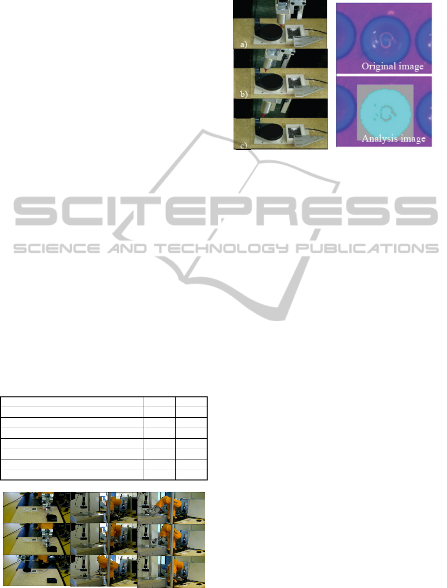
4.1 Pick up Task
The “Picking up 1” task is the first one, and consists
in transporting the part from the delivery base to the
working base with a gripper. This task illustrates
motion management in handling phases. Figure 8
shows some experimental results of the task.
Three tasks were conducted 5 times in sequence
without failure occurring. The priority was set on
overall system integration and Piaget practical
functionality. An additional effort would be required
to explore limits at higher speeds.
Table 1: Each task time of completion.
Figure 8: Experiments of the “Pick up” tasks.
Figure 9: Glue task. Left: Process of putting glue. The tool
is tilted from the phase e) to f). Right: One of the images
of glue detection, cyan shows the existence of glue
(bottom image).
4.2 Glue Task and Detection
Glue task illustrates the integration in Piaget of robot
motion control and vision processes. This assembly
task fixes balls in holes. Pressure and time for
syringe are set in calibration phase (0.3 s). Figure 9
(Left) shows the working process. The syringe
approaches vertically from the start to about 4/5 of
holes, then tilts in order not to touch the protruded
part of the work-piece. It showed good performance.
All holes could be successfully filled with glue.
Next is a quality control. We conducted the glue
detection task, to check whether the holes had a
proper amount of glue by automatic means,
including camera, turning table and glue detection
program. Estimation was performed of the number
of cyan pixels detected in each hole. The number
appears in the results of glue and ball area of the
control form (Figure. 6). The window size was 48 x
48 in the analysis image (Right in Figure. 9). If the
number is sufficient, it shows “OK”. The program
successfully detected that all holes had the glue.
4.3 Ball Task and Ball Detection
After automatic glue task, the ball task ensures the
feeding of ball components and includes a sensor-
based quality control phase. This task illustrates the
integration in Piaget of another capability, the
processing of external, PLC-conditioned, sensor
inputs. Figure 10 shows some of the working
process. The ball tool picks up a ball using negative
pressure at the center of tray (a) and passes through
the filter part in case of having two or three balls in
order to take only one ball (b-c). Then it approaches
the optical sensor to check ball presence (c). Finally
A) Pick up (Transport part to working base) 20 [s]
B) Glue task 6 [min]
C) Pick up (working base to turning table) 30 [s]
D) Glue detection 5 [min]
E) Pick up (turning table to working base) 37 [s]
F) Ball task 31 [min]
G) Pick up (working base to turning table) 30 [s]
H) Ball detection 5 [min]
1-1)
1-2)
1-3)
2-1)
2-2)
2-3)
3-1)
3-2)
3-3)
PiagetfortheSmartControlofComplexRobotizedApplicationsinIndustry
533
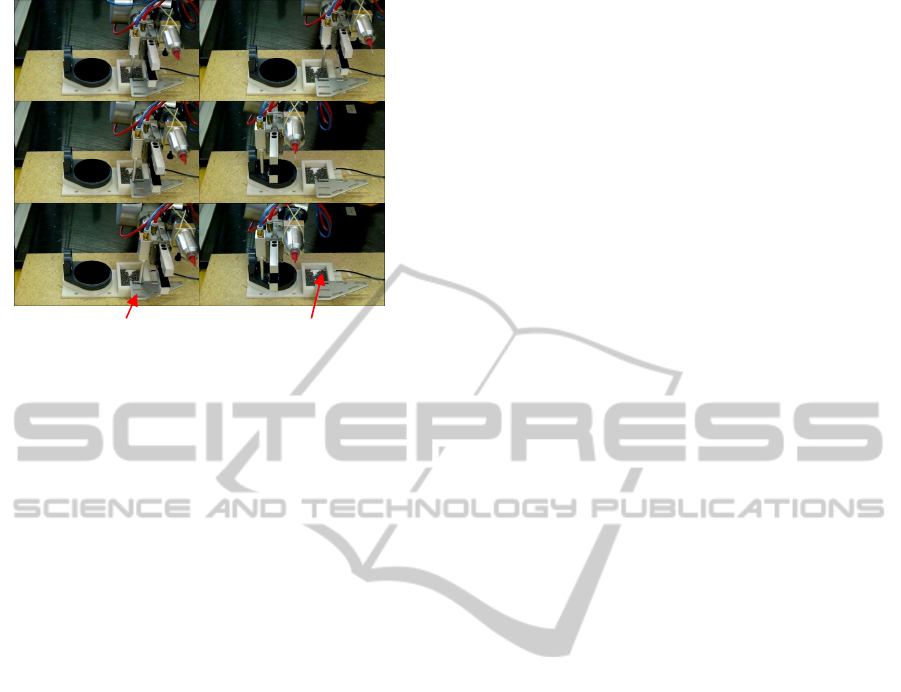
Figure 10: A ball is picked up and put on a hole.
it goes above the part and sets the ball (e-f). The ball
tool only uses On / Off pressure values.
We conducted again a visual check, the
automatic detection of balls. We have used a smaller
detection window (33x33) than for the glue
detection because the glue comes out of hole and
covers the part if the amount of glue is large. The
program successfully detected holes and balls.
4.4 Critical Evaluation
This section presents a critical evaluation of the
proposed approach. Notice first that Piaget has been
experienced a lot, with a variety of resources
including navigation, vocal recognition, Kinect
perception, gesture control, or humanoid mediation.
The specific contribution of the current paper
focuses however on the integration of industrial
robots; it does the job; this may look simpler but
makes in fact the system yet incrementally more
complete: typical previous functionalities remain
fully at disposal.
The described approach is well in line with
current trends: smart/cognitive robots on one hand
inherit from manipulation capabilities of industrial-
grade robots and on the other hand are added
machine-based intelligence (e.g. Konidaris et al.,
2012).
In our complex applications, comparative
evaluation with traditional AI approaches (in
particular neural networks, fuzzy logic, genetic
algorithms, experts systems, predicate calculus)
appears simply impossible, as is impossible for any
neural network to simulate a common computer.
Expertise is typically more critical than learning;
and the former can be ensured without learning (e.g.
DNA). In this sense, Piaget is precious in the
development phase of applications. In operational
mode, critical sources for learning include
perception and communication; in this regard Piaget
allows for learning, and could of course learn more
if additional resources were considered, (e.g.
dedicated sensors on the robotic manipulator, and
possibly associated smart computing elements).
Once integrated in Piaget, robots do not require
their own application dependent software. In the
reported test, operations are defined in Piaget
framework, which includes numerous interactive
actions, forms, and all of the usual incremental
capabilities of Piaget, from very simple to very
powerful.
In the reported experiment, two different
components deserve a special discussion. One is the
integration of the specific industrial robot to Piaget.
This requires, once, expert contributions in terms of
kinematics and communication. The second one is
the programming of the application in Piaget
framework. This is comparatively much simpler.
Functionality is not really limited by Piaget but
rather depends on real-world system components
(e.g. sensors, transmitters, robot arm). In reactive
timing, the most significant limit at supervisory level
is TCP-IP related, i.e. < 0.1 s. More agile processes
are distributed in subsystems, e.g. servo controllers.
In short, Piaget has in particular the
extraordinary capability to integrate existing
components both in time (developmental to
operational phases) and in abstraction levels (from
quasi-physical level to top application-oriented
level). It can both, opportunistically integrate
available resources, and, when necessary,
“subcontract” too fast, distributed controls.
In AI, search is traditionally made for generality.
Quantitative estimation though shows that reality is
infinitely complex; for success, the careful selection
of a goal is a necessary pre-requisite. Piaget is best
adapted to the goal stated in title, and more generally
for smart applications in the current, real-world.
5 CONCLUSIONS
The control of smart robots, and similarly smart
applications in Factory Automation require
programming and control capabilities at the integral
level of many heterogeneous resources. Significant
proposals exist for this purpose, such as ROS, yet we
had to develop an original solution, “Piaget”. Piaget
can be deployed at a very low level, with very fast
capabilities (e.g. 100 nanosecond long time slots in
average), but more and more is concentrates on
a)
b)
c)
d)
e)
f)
Filter part Optical sensor
ICINCO2013-10thInternationalConferenceonInformaticsinControl,AutomationandRobotics
534

higher hierarchical levels, where it brings the
capability to flexibly coordinate multiple, largely
smart and otherwise autonomous subsystems. This
perfectly reflects fundamental constraints in closed-
loop control, which occurs in numerous instances for
a smart system. Piaget can be effective and
interactive in real-time; easy to operate, configure
program, for the average user; and similarly so for
experts, in case of parallel and distributed
implementation. An industrial case is studied,
involving multiple, otherwise independent,
commercially available subsystems, such as
industrial robot arm, PLC, IP camera or joint
controller. A special, multi-tool end-effector, had to
be designed. Highlight is given of selected software
items, relating to the overall application, to the robot
arm, or to the vision part. Experiments are reported,
addressing three of the most significant process
components. The results show good performance.
Ideally, the system should be equipped with a smart
controlling system such as without programming
language for users (Perrollaz et al., 2012);
(Yoshitake et al., 2013), but for complex
applications this goal seems far away and
approaches like Piaget provide a pragmatic solution
today.
REFERENCES
Ando, N., Suehiro, T., Kitagaki, K., Kotoku, T. and Yoon,
W-K. (2005). RT-middleware: Distributed Component
Middleware for RT (Robot Technology). In
Proceedings of 2005 IEEE/RSJ International
Conference on Intelligent Robots and Systems, Alberta,
Canada, Aug. 2005, pp. 3933-3938.
Calvo, I., Perez, F., de Albeniz, O.G. and Etxeberria-
Agiriano, I. (2011). Towards a OMG DDS
communication backbone for factory automation
applications. In Proceedings of 2011 IEEE 16th
Conference on Emerging Technologies & Factory
Autom., Toulouse, France, pp. 1-4.
Dessimoz, J.-D. (2010). Elements of Hybrid Control in
Autonomous Systems and Cognitics. Research and
Education in Robotics - EUROBOT 2010,
International Conference, Rapperswil-Jona,
Switzerland, pp.30-45.
Dessimoz, J.-D. (2011). Cognitics - Definitions and
metrics for cognitive sciences and thinking machines.
Roboptics Editions, Cheseaux-Noréaz, Switzerland,
January 2011, ISBN 978-2-9700629-1-2, pp169.
Dessimoz, J.-D., Gauthey, P.-F. and Omori, H. (2012).
Piaget Environment for the Development and
Intelligent Control of Mobile, Cooperative Agents and
Industrial Robots. In Proceedings of the International
Symposium on Robotics, Taipei, Taiwan, Aug.28-31,
2012.
García, H., Salazar, A. and Orozco, Á. (2012). Statistical
Models for Emotion Recognition using Facial
Expression Analysis. In Proceedings of the 9th
International Conference on Informatics in Control,
Automation and Robotics, Rome, Italy, July, 2012, pp.
238-243.
Konidaris G. et al., Org, (2012) Designing Intelligent
Robots: Reintegrating AI, AAAI Spring Symposium
2012, March 26th-28th, Stanford University.
Liu, Z.-T., Mu, Z., Chen, L.-F., Le, P. Q., Fatichah, C.,
Tang, Y.-K., Tangel M. L., Yan F., K. Ohnishi,
Yamaguchi M., Y. Adachi, Lu, J.-J., Li, T.-Y.,
Yamazaki, Y., Dong, F.-Y. and Hirota, K. (2012).
Emotion Recognition of Violin Music based on
Strings Music Theory for Mascot Robot System. In
Proceedings of the 9th International Conference on
Informatics in Control, Automation and Robotics,
Rome, Italy, July, 2012, pp. 5-14
Maier A., Tack, T. and Niggemann, O. (2012). Visual
Anomaly Detection in Production Plants, In
Proceedings of the 9th International Conference on
Informatics in Control, Automation and Robotics,
Rome, Italy, July, 2012, pp. 67-75.
Mizukawa, M., Sakakibara, S. and Otera, N. (2004).
Implementation and applications of open data network
interface 'ORiN', In Proceedings of SICE 2004 Annual
Conference, Sapporo, Japan, Aug. 2004, vol.2, pp.
1340-1343.
Perrollaz, M., Khorbotly, S., Cool, A., Yoder, J.-D. and
Baumgartner E. (2012). Teachless teach-repeat:
Toward Vision-based Programming of Industrial
Robots. In Proceedings of International Conference
on Robotics and Automation, Saint Paul, MN, USA,
May, 2012, pp. 409-414.
Quigley, M., Gerkey, B., Conley, K., Faust, J., Foote, T.,
Leibs, J., Berger, E., Wheeler, R. and Ng, A. (2009).
ROS: an open-source Robot Operating System. In
Proceedings of Open-Source Software Workshop of
the International Conference on Robotics and
Automation, Kobe, Japan.
Quigley, M. and Jackson, J. (2007). Microsoft robotics
studio: A technical introduction. Robotics &
Automation Magazine, vol.14, no.4, pp.82-87.
Son, M., and Yi, M.-J. (2010). A study on OPC
specifications: Perspective and challenges. In
Proceedings of International Forum on Strategic
Technology, Ulsan, Korea, Oct. 2010, pp.193-197.
Tsai, M.-S., Yen, C.-L. and Yau, H.-T. (2012).
Development of Robust Learning Control and
Application to Motion Control. In Proceedings of the
9th International Conference on Informatics in
Control, Automation and Robotics, Rome, Italy, July,
2012, pp. 148-152.
Yoshitake, S., Nagata, F., Otsuka, A., Watanabe, K. and
Habib, M. K. (2013). Development of CAM system
based on industrial robotic servo controller without
using robot language. Journal of Robotics and
Computer Integrated Manufacturing, Vol. 29, Issue 2,
April 2013, pp. 454 – 462.
PiagetfortheSmartControlofComplexRobotizedApplicationsinIndustry
535
