
A Reactive Trajectory Controller for Object Manipulation in Human
Robot Interaction
Wuwei He
1,2
, Daniel Sidobre
2,3
and Ran Zhao
1,2
1
CNRS, LAAS, 7 Avenue du Colonel Roche, F-31400 Toulouse, France
2
Univ. de Toulouse, LAAS, F-31400 Toulouse, France
3
Univ. de Toulouse, UPS, LAAS, F-31400 Toulouse, France
Keywords:
Robotic, Manipulation, Trajectory Generation, Human-robot Interaction, Control.
Abstract:
This paper presents a reactive trajectory controller for manipulating objects in Human Robot Interaction (HRI)
context. The trajectories to be followed by the robot are provided by a human aware motion planner. The
controller is based on an online trajectory generator, which is capable of calculating a trajectory from an
arbitrary initial condition to a target within one control cycle. The controller is capable of switching to a
new trajectory each time the motion planner provides a new trajectory, changing the frame in which the input
trajectory is controlled and tracking a target or a trajectory in a frame, which moves with respect to the robot
frame. The controller chooses different control modes for different situations. Visual servoing by trajectory
generation is considered as one case of the control situations. Some results obtained with this controller are
presented to illustrate the potential of the approach.
1 INTRODUCTION
In the context of Human Robot Interaction (HRI), in-
tuitive and natural object exchange between human
and robot is one of the basic necessary tasks for object
manipulation. This paper presents a controller which
enables the robot to realize a complete task of object
exchange while respecting human’s safety and other
HRI specifications, such as monitoring the accessibil-
ity of human. This elementary manipulation task de-
mands integration of different elements like geometri-
cal and human-aware reasoning, position and external
force monitoring, 3D vision and human perception in-
formation. The control system presented in this paper
proposes to define a plan as a series of control primi-
tives, each associated with a trajectory segment and a
control mode.
Structure of the Paper: We introduce firstly the ar-
chitecture of the system and present the related work.
In section 2 we present briefly the trajectory genera-
tor and how cost values are associated to the trajectory
based on cost maps. In section 3, we discuss the con-
troller, which is based on the online trajectory genera-
tion. Some results and comparison could be found in
section 4, followed by the conclusion.
1.1 Software Architecture for Human
Robot Interaction
The robots capable of doing HRI must realize sev-
eral tasks in parallel to manage various information
sources and complete tasks of different levels. Figure
1 shows the proposed architecture where each compo-
nent is implemented as a GENOM module. GENOM
(Fleury et al., 1997) is a development environment for
complex real time embedded software.
At the top level, a task planner and supervisor
plans tasks and then supervises the execution. The
module SPARK (Spatial Reasoning and Knowledge)
maintains a 3D model of the whole environment, in-
cluding objects, robots, posture and position of hu-
mans (Sisbot et al., 2007b). It manages also the re-
lated geometrical reasoning of the 3D models, such
as collision risk between the robot parts and between
robot and environment. An important element is that
SPARK produces cost maps, which discribe a space
distribution relatively to geometrical properties like
human accesibility. The softwares for perception,
from which SPARK updates the 3D model of the envi-
ronment, are omitted here for simplicity. The module
runs at a frenquency of 20Hz, limited mainly by the
complexity of the 3D vision and of the perception of
19
He W., Sidobre D. and Zhao R..
A Reactive Trajectory Controller for Object Manipulation in Human Robot Interaction.
DOI: 10.5220/0004427000190028
In Proceedings of the 10th International Conference on Informatics in Control, Automation and Robotics (ICINCO-2013), pages 19-28
ISBN: 978-989-8565-71-6
Copyright
c
2013 SCITEPRESS (Science and Technology Publications, Lda.)
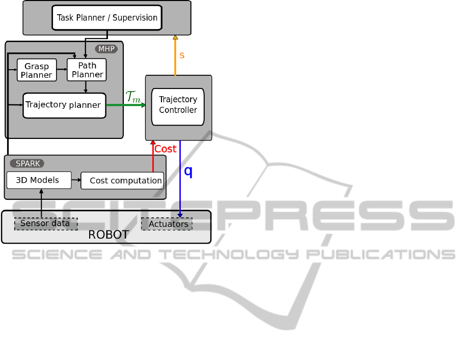
Figure 1: Software Architecture of the robot for HRI ma-
nipulation. T
m
is the main trajectory calculated initially by
MHP(Motion in Human Presence). The controller takes
also cost maps from SPARK. The controller sends control
signals in joint(q in the figure) to the servo system, and dur-
ing the execution, the controller sends the state of the con-
troller (s) to the supervisor
human.
Another important module, MHP (Motion in
Human Presence), integrates path and grasp planner.
RRT (Rapidly exploring Random Tree) and its vari-
ants (Mainprice et al., ) are used by the path planner.
The paths could be in Cartesian or joint spaces de-
pending on the task type. From the path, an output
trajectory is computed to take the time into account.
MHP calculates a new trajectory each time the task
planner defines a new task or when the supervisor de-
cides that a new trajectory is needed for the changes
of the environment.
The system should adapt its behavior to the dy-
namic environment, mainly the human activities. But
as the planning algorithms are time consuming, we in-
troduce a trajectory controller that runs at 100 Hz, an
intermediate frequency between the one of the MHP
planner and the one of the fast robot servo system.
This trajectory controller allows the system to adapt
faster the trajectory to the environment changes.
The main functionalities of the whole controller are:
• A decision process capable of integrating in-
formation form high-level software and building
control primitives by segmenting the trajectory
based on the HRI specifications.
• Algorithms for target or trajectory tracking, tra-
jectory switching, and coordinates transforma-
tion.
• A low-level collision checker and a monitor of the
external torques for the safety issues.
1.2 Related Works
Reactive controller for object manipulation is a re-
search topic that is part of the fundamentals of robotic
manipulation. Firstly, trajectory generation based ap-
proaches have been developed. In (Buttazzo et al.,
1994), results from visual system pass firstly through
a low-pass filter. The object movement is modeled
as a trajectory with constant acceleration, based on
which, catching position and time is estimated. Then
a quintic trajectory is calculated to catch the object,
before being sent to a PID controller. The maximum
values of acceleration and velocity are not checked
when the trajectory is planned, so the robot gives up
when the object moves too fast and the maximum
velocity or acceleration exceeds the capacity of the
servo controller. In (Gosselin et al., 1993), inverse
kinematic functions are studied, catching a moving
object is implemented as one application, a quintic
trajectory is used for the robot manipulator to joint the
closest point on the predicted object movement tra-
jectory. The systems used in those works are all quite
simple and no human is present in the workspace. A
more recent work can be found in (Kr
¨
oger and Padial,
2012), in which a controller for visual servoing based
on Online Trajectory Generation (OTG) is presented,
and the results are promising.
Secondly, the research area of visual servoing pro-
vides also numerous results, a survey of which were
presented by Chaumette and Hutchinson (Chaumette
and Hutchinson, 2006), (Chaumette and Hutchinson,
2007) and a comparison of different methods can be
found in (Farrokh et al., 2011). Classical visual servo-
ing methods produce rather robust results and stability
and robustness can be studied rigorously, but they are
difficult to integrate with a path planner, and could
have difficulties when the initial and final positions
are distant.
Another approach to achieve reactive movements
is through Learning from Demonstration(LfD). In
(Calinon and Billard, 2004) and (Vakanski et al.,
2012), points in the demonstrated trajectory are clus-
tered, then a Hidden Markov Model(HMM) is built.
Classification and reproduction of the trajectories are
then based on the HMM. A survey for this approach
is proposed in (Argall et al., 2009). Although LfD
can produce the whole movement for objects manip-
ulation, many problems may arise in a HRI context
ICINCO2013-10thInternationalConferenceonInformaticsinControl,AutomationandRobotics
20

as LfD demands large set of data to learn, and the
learned control policies may have problem to cope
with a dynamic and unpredictable environment where
a service robot works.
Our approach to build the controller capable of
controlling a complete manipulation tasks is based on
Online Trajectory Generation. More results on tra-
jectory generation for robot control can be found in
(Liu, 2002), (Haschke et al., 2008), and (Kr
¨
oger et al.,
2006). The controller is capable of dealing with vari-
ous data in HRI context. Compared to methods men-
tioned above, approaches based on OTG have the fol-
lowing advantages:
• The integration with a path planner is easy and
allows to comply with kinematic limits like the
one given by human safety and comfort.
• The path to grasp a complex moving object is de-
fined in the object frame, making sure that the
grasping movement is collision free.
• The trajectory based method allows to create a
simple standard interface for different visual and
servo systems, easy plug-in modules can be cre-
ated.
The controller integrates various information from
high-level software. More information about human-
aware motion planning in the system can be found
in (Mainprice et al., 2011). More about geometri-
cal reasoning can be found in (Sisbot et al., 2011),
(Mainprice et al., ), and (Sisbot et al., 2007a). Phys-
ical Human Robot Interaction is a dynamic research
area including various aspects, such as safety, control
architecture, planning, human intention recognition,
and more. Readers may refer to (De Santis et al.,
2008), (Sidobre et al., 2012), and (Strabala et al.,
2013), among many others, for more information of
this research field.
2 TRAJECTORY AND CONTROL
PRIMITIVES
2.1 Online Trajectory Generation
Trajectories are time functions defined in geometri-
cal spaces, mainly Cartesian space and joint space
for robots. The books from Biagiotti (Biagiotti and
Melchiorri, 2008) and the one from Kroger (Kr
¨
oger,
2010) summarize background materials. For detailed
discussion about the trajectory generator used in the
system, the reader can refer to (Broqu
`
ere et al., 2008)
and (Broqu
`
ere and Sidobre, 2010), here we describe
some results without further discussion.
Given a system in which position is defined by a
set of coordinate X, a trajectory T is a function of
time defined as:
T : [t
I
,t
F
] −→ R
N
(1)
t 7−→ T (t) = X(t)
The trajectory is defined from the time interval
[t
I
,t
F
] to R
N
where N is the dimension of the motion
space. The trajectory T (t) can be a direct function of
time or the composition C (s(t)) of a path C (s) and a
function s(t) describing the time evolution along this
path. The time evolution could be used in the con-
troller to slow down or to accelerate when necessary
(Broqu
`
ere, 2011).
Our trajectory generator is capable of generating
type V trajectories defined by Kroger (Kr
¨
oger, 2010)
as satisfying:
X(t
I
) ∈ R X(t
F
) ∈ R |V (t)| 6 V
max
V (t
I
) ∈ R V (t
F
) ∈ R |A(t)| 6 A
max
(2)
A(t
I
) ∈ R A(t
F
) ∈ R |J(t)| 6 J
max
Where X, V , A and J are respectively the position,
the velocity, the acceleration and the jerk.
For a motion of dimension N, the algorithms find
a trajectory X(t), which satisfies:
1. The initial conditions (IC): X(t
I
) = X
I
, V (t
I
) = V
I
and A(t
I
) = A
I
;
2. The final conditions (FC): X(t
f
) = X
F
, V (t
f
) =
V
F
and A(t
f
) = A
F
;
3. The continuity class of the trajectory is C
2
.
4. The kinematics limits V
max
, A
max
and J
max
.
The problem is solved by a series of 3
rd
degree
polynomial trajectories. Such a trajectory is com-
posed of a vector of one-dimensional trajectories:
T (t) = (
1
Q(t),
2
Q(t),... ,
N
Q(t))
T
for joint motions
or T (t) = (
1
X(t),
2
X(t), . ..,
N
X(t))
T
in Cartesian
space.
For the discussion of the next sections, we de-
fine Motion Condition as the position, velocity and
acceleration at time t of the trajectory: M(t) =
(X(t),V (t), A(t)). Once the trajectory is calculated,
the function M(t) = getMotion(t,T ) returns the Mo-
tion Condition on trajectory T at time t.
2.2 Control Primitives
In HRI, the robot does various tasks like picking up
an object, giving an object to human, taking an ob-
ject from the human. For each of the task, a path is
planned to realize it, and then the path is transformed
into a trajectory. The controller designed here takes
directly the trajectory as input and segments it based
on the cost maps.
AReactiveTrajectoryControllerforObjectManipulationinHumanRobotInteraction
21
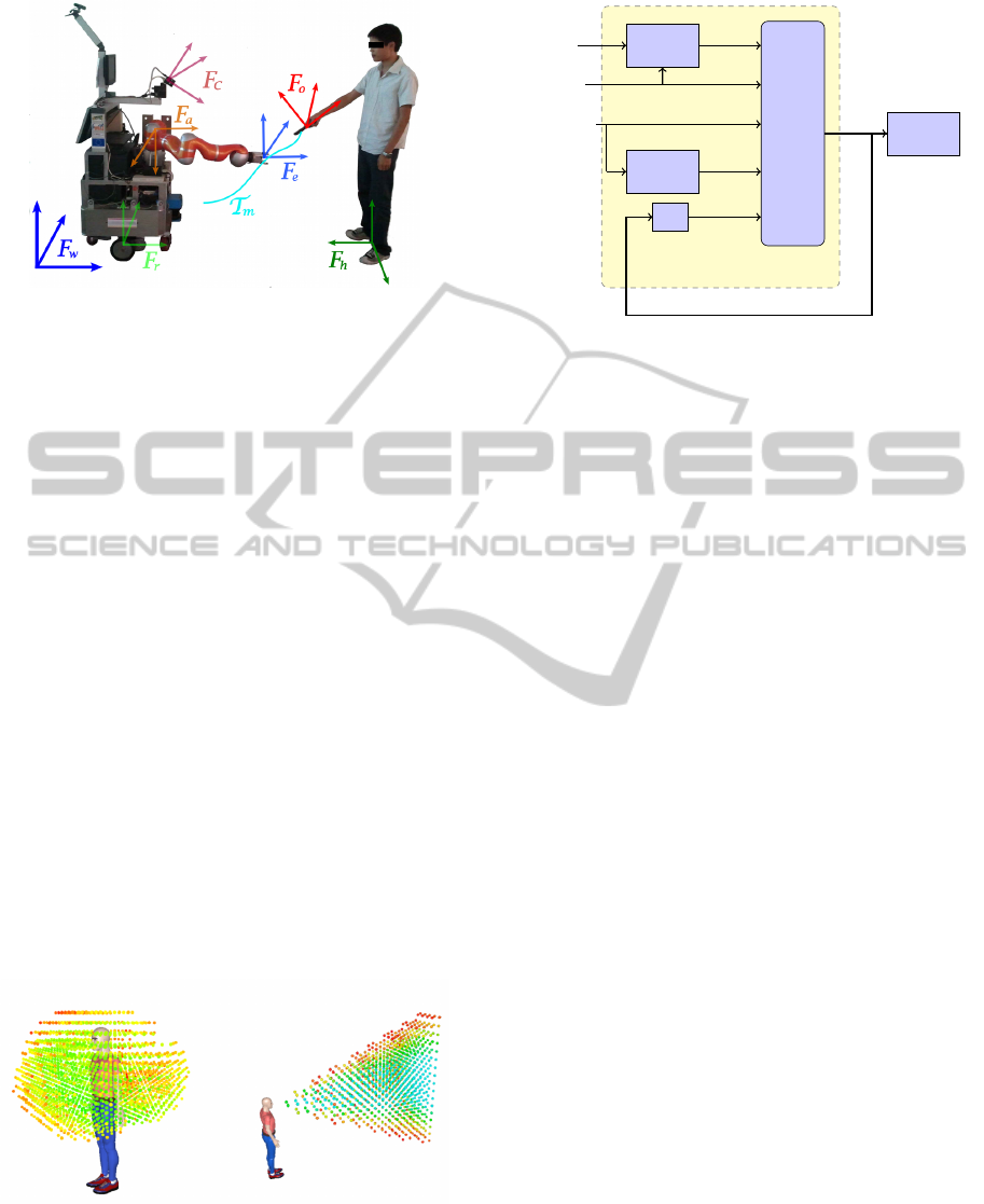
Figure 2: Frames for object exchange manipulation: F
w
:
world frame; F
r
: robot frame; F
c
: camera frame; F
e
: end
effector frame; F
o
: object frame; F
h
: human frame. The
trajectory realizing a manipulation should be controlled in
different task frames.
Figure 2 shows the basic frames needed to define
a task. The trajectory T
m
defines the move that allows
the robot to do the task of grasping an object handed
by the human.
Based on the cost values associated to each point
of the trajectory, the trajectory is divided into seg-
ments associated to a control strategy. The 3D cost
maps used are of different types: collision risk map
calculated based on the minimum distance between
trajectory and the obstacles; visibility and reachabil-
ity map of a human (Sisbot et al., 2011) and safety
and comfort 3D map of a human, Figure 3 shows two
examples of cost maps. For example, when the risk
of collision with the robot base is high, the trajectory
can be controlled in robot the frame. Similarly, in
the case where the human is handing an object to the
robot, the grasping must be controlled in the object
frame. (Sidobre et al., 2012) details other aspects of
the use of cost maps to plan manipulation tasks.
To simplify the presentation, in the reminder of
the paper we focus on the manipulation tasks where
Figure 3: Left: 3D reachability map for a human. Green
points have low cost, meaning that it is easier for the human
to reach, while the red ones, having high cost, are difficult to
reach. One application is that when the robot plans to give
an object to a human, an exchange point must be planned
in the green zone. Right: 3D visibility map. Based on vis-
ibility cost, the controller can suspend the execution if the
human is not looking at the robot.
Trajectory Control Modes
Traj Seg
MHP
Robot
Collison
Checker
SPARK
Perception
C P (t)
T
m
R
C (t)
Controller
M
t+T
z
−1
M
t
Figure 4: Input and output of the controller. T
m
is the tra-
jectory computed by MHP, it is then segmented into control
primitives (C P (t)). Traj Seg represents trajectory segmen-
tation. C (t) are the cost values. R represents the tranfor-
mation matrices, giving the position of the target and of the
robot. M
t
is the current state of the robot, M
t+T
is desired
motion condition for the next control cycle. z
−1
represents
delay of a control cycle.
a human hands over an object to the robot. During
the manipulations, the human moves and the differ-
ent frames defining the task move accordingly. Based
on the change of cost values, we divide the trajectory
T
m
in Figure 2 into three segments, as illustrated in
the configuration space in the left part of Figure 7.
In the figure, the points connecting the trajectory seg-
ments are depicted by red dots. The first segment T
1
,
which is defined in the robot frame, has a high risk
of auto-collision. When human or object moves, the
cost value of collision risk stays the same. Segment
T
2
has a lower collision cost value, so modifying the
trajectory inside this zone does not introduce high col-
lision risk. The end part, segment for grasping move-
ment T
g
, has a high collision cost value. To ensure
the grasping succeeds without collision this segment
of trajectory should be controlled in the moving ob-
ject frame.
We name task frame the frame in which the trajec-
tory must be controlled. We define a control primitive
C P by the combination of five elements: a segment
of trajectory, a cost function, a task frame, a control
mode, and a stop condition.
C P (t) = (T
seg
(t), C (t), F , O, S)
T
(3)
In which, T
seg
(t) is the trajectory segment, C (t)
is the cost value associated to the trajectory which is
monitored during the execution of a control primitive,
F is the task frame, O is the control mode which we
will define in next section, and S is the stop condition
of the control primitive. For example, the grasping
movement includes five elements: the trajectory seg-
ment T
g
, the high collision risk cost value C (t), the
ICINCO2013-10thInternationalConferenceonInformaticsinControl,AutomationandRobotics
22

Figure 5: A simple case of grasp. Left: a planned grasp de-
fines contact points between the end effector and the object.
Right: To finish the grasping, the manipulator must follow
the blue trajectory P
1
- P
c
, and then close the gripper. This
movement must be controlled in the object frame F
o
.
task frame F
o
, the control mode as trajectery tracking,
and the stop condition S as a predefined threshold for
the distance between the robot end effector and the
end point of T
g
. In the literature, Manipulation Prim-
itives or Skill Primitives are often the concept for the
intermediate level between planning and control and
have been discussed in numerous works, as in (Kr
¨
oger
et al., 2011).
Using the definition of control primitives (CP (t))
and Motion Condition: M(t) = (X(t),V (t), A(t)), the
different components of the trajectory controller and
the input and output are presented in Figure 4. The
initial trajectory T
m
is segmented into a series of
C P (t). The cost values C (t) are used during the seg-
mentation, they are also monitored by the controller
during execution of a control primitive. The collision
checker integrates data from vision, human percep-
tion and encoder of the robot. It prevents collision
risk by slowing down or suspending the task execu-
tion. With all the data and the current Motion Con-
dition M
t
of the robot, different control modes can
compute Motion Condition for the next control cycle,
which are the input for the robot sorvo system.
Figure 5 shows the last control primitive of grasp-
ing an object. It is similar to the end part, T
g
, of the
trajectory in Figure 2. The grasp position, the contact
points and the final trajectory are planned by the grasp
planner. More details on the grasp planner are given
in (Bounab et al., 2008) and (Saut and Sidobre, 2012).
When the object moves, the object frame F
o
and the
path of the trajectory moves also. So to avoid col-
lision, the trajectory of these control primitives must
be controlled in the object frame F
o
.
3 REACTIVE TRAJECTORY
CONTROL
At the control level, a task is defined by a series of
control primitives, each defined by a quintuplet. The
first level of the proposed trajectory controller is a
state machine, which controls the succession of the
control modes, the collision managing and other spe-
cial situations. Target tracking and trajectory tracking
are parts of the control modes presented after the state
machine.
3.1 Execution Monitoring
A state machine controls the switching between the
different control modes associated to each control
primitive and monitors the execution. Due to human
presence, the robot environment is moving and the
control task must be adapted accordingly. The state
machine can also suspend or stop the control of a con-
trol primitive like depicted in Figure 6.
Suspend Events: When the visual system fails or
the target becomes unavailable, or because of some
specific human activities based on the monitoring of
cost value C (t), the trajectory controller should sus-
pend the task.
Stop Events: Whatever the control mode chosen,
unpredictable collisions can occur and they must stop
the robot. Our controller uses two modules to detect
these situations. The first one based on (De Luca and
Ferrajoli, 2008) monitors the external torques. The
second is a geometric collision checker based on re-
sults from (Larsen et al., 1999), it updates a 3D model
of the workspace of the robot, and runs at the same
frequency as the trajectory controller.
Slow Down On Trajectory: Based on the input
cost function, the controller can slow down on the
main trajectory by changing the time function s(t).
Imagine that a fast movement could cause some peo-
ple anxiety when the robot is close to them, for exam-
ple. Details about this specific situation can be found
in (Broqu
`
ere, 2011). In this situation, the controller is
still executing the task but only at a slower speed.
Each elementary controller based on online trajec-
tory controller is implemented with a simple state ma-
chine inside.
Figure 6: In the left, each circle represents the controller
of a control primitive. The system can suspend or stop the
execution of a control primitive.
AReactiveTrajectoryControllerforObjectManipulationinHumanRobotInteraction
23

obstacle
obstacle
obstacle
obstacle
Object
v
Object
Figure 7: Left: trajectories of the control primitives. Right:
trajectory switching for the controller due to the movement
of an obstacle.
3.2 Trajectory Control Modes
Depending on the context defined by the control prim-
itives, different control strategies must be developed.
Online trajectory generator gives a flexible solution
to build these controllers, which can easily react to
unforeseen sensor events and adapt the kinematic pa-
rameters, mainly velocity, to the environment context.
Switching to a new trajectory or a new frame in which
the trajectory is controlled is also possible.
The main idea of the controller is to compute and
follow a trajectory while joining up the target trajec-
tory or a target point from the current state. Several
control modes are defined to solve the reactive HRI
manipulation problem.
Control Mode 1: Target Tracking. If we suppose the
robot is in an area without risk of collision, the sys-
tem can track the end point of the trajectory. In this
case, the controller generates iteratively a trajectory
to reach the end point and send the first step of this
trajectory to a low-level controller. In the special case
where the controller does target tracking with visual
system, it does visual servoing.
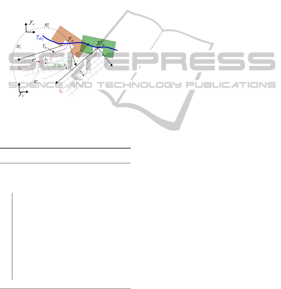
Figure 8 shows the details of the trajectory con-
trol mode for Target Tracking. The object is at posi-
tion O at current time, and moves following the curve
T
ob j
. This curve is obtained by a simple Kalman fil-
ter, building a movement model from the results of
3D vision system. F
r
is the robot base frame, F
c
and
F
o
are camera frame and object frame, respectively.
Also, R
c
r
is the 4 ×4 transformation matrix from F
r
to
F
c
and R
o
c
the transformation matrix from F
c
to F
o
.
They are all in dashed line and they change with time
when the humans or objects move. Initially, the robot
is at point P
e
, since there is no risk of collision, the
controller can simply track point P
2
, which is the end
point of the segment. It is also possible for the robot
to join up the trajectory at another point P
joint
defined
Figure 8: Control Mode 1. The robot tracks a point. The
object moves to the right, it is drawn at two times: firstly in
brown for time t
1
and then in green at time t
2
. In both cases,
the entry point P
2
of the trajectory T
g
is drawn relatively to
the object frame F
o
.
in the object frame which is the task frame. The de-
tails of the algorithm is given in Algorithm 1 where:
T : duration of one control cycle.
M
r
: current motion condition of the robot, so M
r
=
(X
r
,V
r
,A
r
).
δ: distance threshold to stop the tracking process.
M
g
(t): motion conditions at time t on trajectory T
g
.
M
P
2
: motion conditions of the target P
2
on the main
trajectory, which is calculated by the planner.
MaxLoop: the maximum times the loop repeats for
the controller to track the target or the trajectory.
Once the time exceeds the value, the trajectory
controller is suspended and a signal is sent to the
supervisor, requiring the replanning of new task
or a new path to realize the task.
X,Q: input signal in Cartesian space and in joint
space for low-level controller.
Algorithm 1: Control for target tracking (Control
Mode 1).
input : Target point P
2
;
while
(distance(P
2
,M
r
) > δ) ∧ (Loop < MaxLoop)
do
system time t = t + T , Loop = Loop + 1;
Update perception data;
if Collision Detected then Emergency stop;
if Suspend Events Occur then Suspend
task;
Coordinates transformations;
Generate Type V control trajectory T (t),
for which: IC = M
r
, FC = M
P
2
;
X = getMotion(t + T, T (t));
Inverse kinematics: X → Q;
Q to the position servo system;
end
ICINCO2013-10thInternationalConferenceonInformaticsinControl,AutomationandRobotics
24
Control Mode 2: Trajectory tracking in Task Frame.
Once robot reaches point P
2
, it starts the grasping
movement, which corresponds to T
g
in Figure 7. The
object is still moving, but as the robot is in the high
cost zone, it should track the main trajectory in the
task frame. The details of the control mode is given
in Algorithm 2.
Figure 9 shows the details of the control mode, all
the frames and object movements are the same as in
Figure 8, but the robot is at point P
0
e
. The robot tracks
T
g
in the frame F
o
, and will end up executing T
0
(t)
in the robot frame.
O
O'
Figure 9: Control Mode 2. Control mode. Object at time
t
1
is colored in light brown, and green at time t
2
. It follows
a movement model given as the blue trajectory T
ob j
. The
purple trajectory for grasping T
g
stays unchanged in the ob-
ject frame. The robot tracks the trajectory T
g
as it does the
grasping movement.
Algorithm 2: Control for trajectory tracking in a
moving work frame (Control Mode 2).
input : Trajectory segment T
g
;
while
(distance(P
c
,M
r
) > δ) ∧ (Loop < MaxLoop))
do
system time t = t + T , Loop = Loop + 1;
Update perception data and object
movement model;
if Collision Detected then Emergency stop;
if Suspend Events Occur then Suspend
task;
Coordinates transformations;
M
T
g
= getMotion(t + T, T
g
);
M
ob ject
= getMotion((t + T, T
ob j
);
X = M
T
g
+ M
ob ject
;
Inverse kinematics: X → Q;
Q to the position servo system;
end
Control Mode 3: Path re-planning and trajectory
switch: during the execution, a path can be re-
planned, for example when an obstacle moves (see
Fig. 7). A new trajectory is computed and given
to the controller that switches to the new trajectory.
While the controller is following the trajectory T
m
,
an obstacle moves and invalidates the initial trajec-
tory. Then the system provides the controller with a
new trajectory T
0
m
beginning at time t
1
in the future.
The controller anticipates the switch, and when the
robot reaches P
t
1
at time t
1
, the robot switches to the
new trajectory T
0
m
. Because the new trajectory T
0
m
is calculated using the state of the robot at time t
1
as
its initial condition, the trajectory is switched without
problem. The controller keeps the possibility of path
re-planning. In some cases, a new path is needed to
accomplish the task.
In this paper, we essentially solved the problem
of the task of grasping a moving object held by the
human counterpart. For other tasks, like picking an
object, giving an object to human or putting an object
on the table, the same functionalities can also be used.
For example, putting an object on a moving platform
would require the end segment of the main trajectory
to be controlled in the frame of the platform, which
moves in the robot frame. Likewise giving an ob-
ject to a moving human hand will require the manip-
ulator to track the exchange point, normally planned
by a human-aware motion planner till the detection
that human grasps the object successfully. Although
a general algorithm to decompose the tasks into con-
trol primitives is still to develop, the basic HRI tasks
can all be controlled by the control modes discussed
above.
4 MANIPULATION RESULTS
We focus on some results of how the controller is
integrated in a HRI manipulator. For the perfor-
mance of the trajectory generator, readers may refer
to (Broqu
`
ere et al., 2008) and (Broqu
`
ere, 2011).
The controller has been implemented on the robot
Jido at LAAS-CNRS. Jido is a mobile manipulator ,
built up with a Neobotix mobile platform MP-L655
and a Kuka LWR-IV arm. Jido is equipped with one
pair of stereo cameras and an ASUS Xtion depth sen-
sor. The software architecture that we used for Jido
is presented in 1.1. Note that the pan-tilt stereo head
may move during manipulations, then the transforma-
tion matrix from robot frame to camera frame is up-
dated at the same frequency as the controller. The
stereovision system uses marks glued on manipulated
objects for localization. Unfortunately, the localiza-
tion of these marks is highly sensible to lighting con-
ditions and the estimated position of the object O in
the robot frame F
r
is very noisy and unstable. Figure
AReactiveTrajectoryControllerforObjectManipulationinHumanRobotInteraction
25
10 shows the results returned by the 3D-vision sys-
tem in poor lighting conditions and the result given
by a Kalman filter. Even when raw data oscillates,
this filter is capable to reduce the offset at the price of
an acceptable delay. This reduces the oscillations of
the robot arm too.
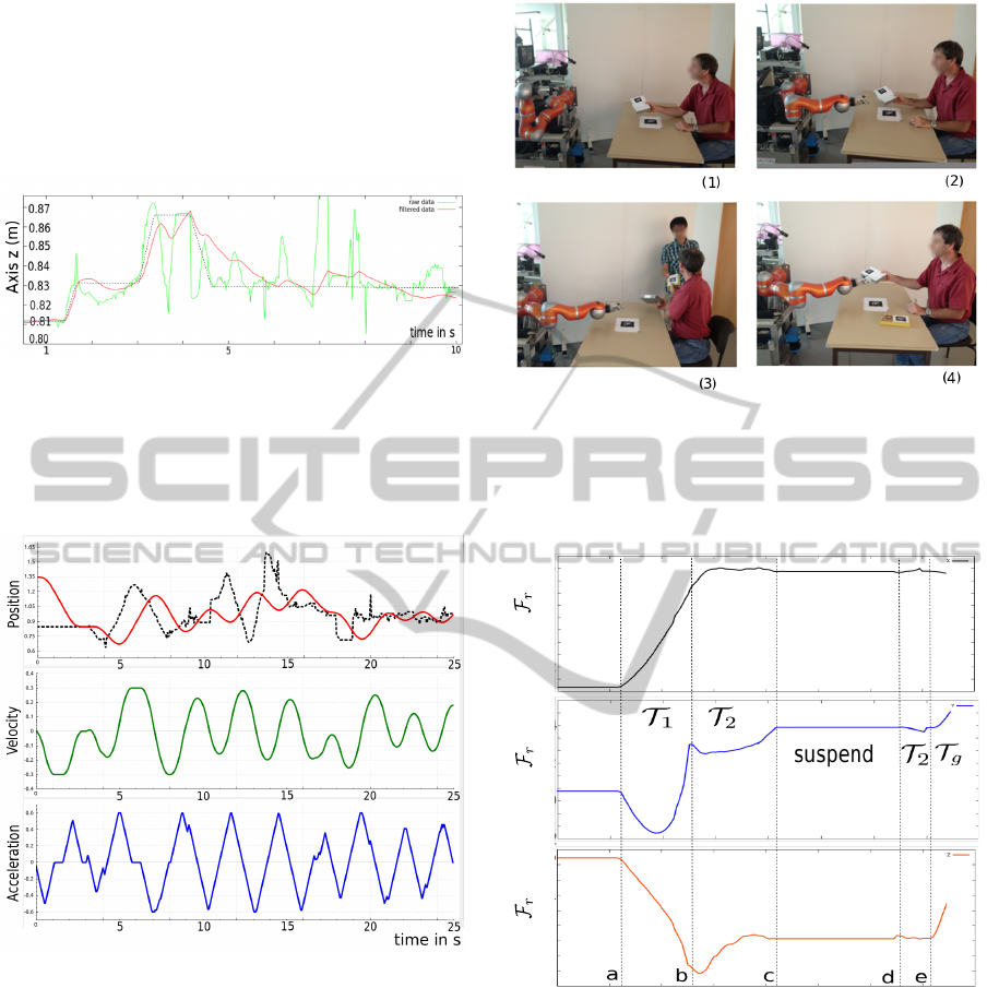
Figure 10: Instability of the 3D vision in poor lighting con-
dition. The green curve shows axis z of the localization
result of an object in the robot frame over 10 seconds and
the red one shows the filtered result. The object was held
by a human that intended to move the object accordingly to
the black dashed curve.
Figure 11: Results of robot tracking a target: position (in
m), velocity (in m/s) and acceleration (in m/s
2
) during the
tracking for 25 seconds. The black dashed line is the tar-
get position, with noise of the 3D vision, and the red line
is the position of the robot, which tracks the target with a
delay. The positions of the robot are calculated from mea-
sured joint values and the kinematic model, while velocity
and acceleration are estimated. The velocity, acceleration
and jerk are always limited, maintaining a smooth tracking
process.
Figure 11 shows the results of the target tracking
by the trajectory controller, as in Case 2, over 25 sec-
onds. For simplicity, only axis X is shown. The black
dashed line is the position of the target, generated by
the 3D vision system. The red line is the position of
the robot. The two bottom diagrams show the veloc-
ity and acceleration of the robot in the same period.
Figure 12: (1): The controller is given the task of receiving
the object from human. It tracks the first segment in the
robot frame. (2): The object is moving and the robot tracks
a target. (3): Human is distracted by another human and the
task is suspended. (4): Human returns to the task, and the
robot resumes the task and grasps the object.
time in s
0 20
40
60
Axis x in
Axis y in
Axis z in
1.0
-0.2
0.0
0.6
10
30
50
0.2
0.4
0.6
0.8
0.4
0.2
0.0
0.2
0.4
(m)
(m)
(m)
0.8
Figure 13: Real position of the robot arm end effector in the
robot frame. The motion starts at time a; Between a and
b: the controller tracks the first trajectory segment T
1
in F
r
;
From b to c and d to e: target tracking; From c to d: the
task is suspended; From e to end: the grasping movement
controlled in F
o
.
Firstly, we can see that the controller produces robust
behavior to the noise in the visual system. Secondly,
the velocity and acceleration of the robot are saturated
as type V trajectories and calculated.
Finally, we show the behavior of the controller for
a complete manipulation task. Figure 12 shows the
scenario of the manipulation and Figure 13 shows the
ICINCO2013-10thInternationalConferenceonInformaticsinControl,AutomationandRobotics
26

real position of the robot end effector in the robot
frame (see figure 2 for the axes assignment of the
robot base). The high-level task planner plans a task
to receive the object. When the robot sees the ob-
ject held by the human, the grasp planner calculates
a valid grasp and the path planner with the trajectory
generator plans the main trajectory for the robot to
take the object.
The trajectory is divided into three segments by
the controller, and different control modes are chosen.
As we as seen above, each control primitive is asso-
ciated to a trajectory segment. In this case, we obtain
three segments, the first one is controlled in the robot
frame, the second is defined as the tracking of the en-
try point of the third segment and the third segment is
a trajectory defined in the object frame.
During the target tracking, human is distracted be-
cause a second human arrives and gives an object to
him. High-level software detects this event by moni-
toring the visibility cost map of the human. Because
of the event, the controller suspends the task. It re-
sumes the tracking when the human look again at the
robot and the object to exchange come back in the
reachable zone. Then, the grasping movement is fin-
ished. Note the performance of the target tracking
process in the time intervals: between b to c, and be-
tween d to e. The controller finished the task reac-
tively without the need of task or path replanning. The
results shows that a reactive controller can be built
based on Online Trajectory Generation, and as it is
more responsive for the human, the robot is easier to
interact with. Before the implementation of the reac-
tive controller, the human needs to hold still the object
for the robot to grasp successfully.
5 CONCLUSIONS
A reactive trajectory controller has been presented
with some results relative to a robot grasping an ob-
ject held by a human. The first results presented il-
lustrate the versatility of the controllers based on on-
line trajectory generation. In the example shown here,
the controller switch between frames and suspend the
control task during the time the human is distracted.
The trajectory controller proposed uses an online
trajectory generator to build a trajectory to join up the
trajectory to follow. It is very simple to use and imple-
ment and gives an efficient solution to follow trajec-
tories and track moving objects in the HRI context.
More precisely, it can adapt kinematic limits to the
changing state of the scene and switch between tra-
jectories and control modes.
The challenge is now to extend this type of trajec-
tory controller and the concept of control primitives to
manage forces, to handle events based on force sens-
ing and to control dual arm manipulators.
ACKNOWLEDGEMENTS
This work has been supported by the European Com-
munity’s Seventh Framework Program FP7/2007-
2013 “SAPHARI” under grant agreement no. 287513
and by the French National Research Agency
project ANR-07-ROBO-0011 “ASSIST” and ANR-
10-CORD-0025 “ICARO”.
REFERENCES
Argall, B. D., Chernova, S., Veloso, M., and Browning, B.
(2009). A survey of robot learning from demonstra-
tion. Robotics and Autonomous Systems, 57(5):469 –
483.
Biagiotti, L. and Melchiorri, C. (2008). Trajectory Planning
for Automatic Machines and Robots. Springer.
Bounab, B., Sidobre, D., and Zaatri, A. (2008). Central axis
approach for computing n-finger force-closure grasps.
Robotics and Automation, 2008. ICRA 2008. IEEE In-
ternational Conference on, pages 1169–1174.
Broqu
`
ere, X. (2011). Planification de trajectoire pour la
manipulation d’objets et l’interaction Homme-robot.
PhD thesis, LAAS-CNRS and Universit
´
e de Toulouse,
Paul Sabatier.
Broqu
`
ere, X. and Sidobre, D. (2010). From motion plan-
ning to trajectory control with bounded jerk for ser-
vice manipulator robots. In IEEE Int. Conf. Robot.
And Autom.
Broqu
`
ere, X., Sidobre, D., and Herrera-Aguilar, I. (2008).
Soft motion trajectory planner for service manipula-
tor robot. Intelligent Robots and Systems, 2008. IROS
2008. IEEE/RSJ International Conference on, pages
2808–2813.
Buttazzo, G., Allotta, B., and Fanizza, F. (1994). Mouse-
buster: A robot for real-time catching. IEEE Control
Systems Magazine, 14(1).
Calinon, S. and Billard, A. (2004). Stochastic gesture pro-
duction and recognition model for a humanoid robot.
In Intelligent Robots and Systems, 2004. (IROS 2004).
Proceedings. 2004 IEEE/RSJ International Confer-
ence on, volume 3, pages 2769 – 2774 vol.3.
Chaumette, F. and Hutchinson, S. (2006). Visual servo con-
trol. part i: Basic approaches. IEEE Robotics and Au-
tomation Magazine, 4(13).
Chaumette, F. and Hutchinson, S. (2007). Visual servo con-
trol. part ii: Advanced approaches. IEEE Robotics and
Automation Magazine, 1(14).
De Luca, A. and Ferrajoli, L. (2008). Exploiting robot
redundancy in collision detection and reaction. In
Intelligent Robots and Systems, 2008. IROS 2008.
AReactiveTrajectoryControllerforObjectManipulationinHumanRobotInteraction
27

IEEE/RSJ International Conference on, pages 3299 –
3305.
De Santis, A., Siciliano, B., De Luca, A., and Bicchi, A.
(2008). An atlas of physical human–robot interaction.
Mechanism and Machine Theory, 43(3):253–270.
Farrokh, J.-S., Lingfeng, D., and William, J. (2011). Com-
parison of basic visual servoing methods. IEEE/ASME
Transactions on Mechatronics, 16(5).
Fleury, S., Herrb, M., and Chatila, R. (1997). Genom: A
tool for the specification and the implementation of
operating modules in a distributed robot architecture.
In IEEE/RSJ Int. Conf. on Intel. Rob. And Sys.
Gosselin, G., Cote, J., and Laurendeau, D. (1993). Inverse
kinematic functions for approach and catching oper-
ations. IEEE Trans. Systems, Man, and Cybernetics,
23(3).
Haschke, R., Weitnauer, E., and Ritter, H. (2008). On-Line
Planning of Time-Optimal, Jerk-Limited Trajectories.
In IEEE/RSJ International Conference on Intelligent
Robots and Systems, 2008. IROS 2008, pages 3248–
3253.
Kr
¨
oger, T. (2010). On-Line Trajectory Generation in
Robotic Systems, volume 58 of Springer Tracts in Ad-
vanced Robotics. Springer, Berlin, Heidelberg, Ger-
many, first edition.
Kr
¨
oger, T., Finkemeyer, B., and Wahl, F. (2011). Manipula-
tion Primitives A Universal Interface between Sensor-
Based Motion Control and Robot Programming, vol-
ume 67 of Springer Tracts in Advanced Robotics.
Springer Berlin Heidelberg.
Kr
¨
oger, T. and Padial, J. (2012). Simple and Robust Vi-
sual Servo Control of Robot Arms Using an On-Line
Trajectory Generator. 2012 IEEE International Con-
ference on Robotics and Automation.
Kr
¨
oger, T., Tomiczek, A., and Wahl, F. (2006). Towards
on-line trajectory computation. In Proceedings of
the IEEE/RSJ International Conference on Intelligent
Robots and Systems, Beijing, China. Citeseer.
Larsen, E., Gottschalk, S., Lin, M., and Manocha, D.
(1999). Fast proximity queries with swept sphere vol-
umes.
Liu, S. (2002). An on-line reference-trajectory genera-
tor for smooth motion of impulse-controlled industrial
manipulators. In 7th International Workshop on Ad-
vanced Motion Control, pages 365–370.
Mainprice, J., Sisbot, E., Jaillet, L., Cort
´
es, J., Sim
´
eon, T.,
and Alami, R. (2011). Planning Human-aware mo-
tions using a sampling-based costmap planner. In
IEEE Int. Conf. Robot. And Autom.
Mainprice, J., Sisbot, E., Sim
´
eon, T., and Alami, R. In IARP
Workshop on Tech. Challenges for Dependable Robots
in Human Environments.
Saut, J.-P. and Sidobre, D. (2012). Efficient models for
grasp planning with a multi-fingered hand. Robotics
and Autonomous Systems, 60.
Sidobre, D., Broqu
`
ere, X., Mainprice, J., Burattini, E.,
Finzi, A., Rossi, S., and Staffa, M. (2012). Human–
robot interaction. Advanced Bimanual Manipulation,
pages 123–172.
Sisbot, E., Ros, R., and Alami, R. (2011). Situation as-
sessment for human-robot interactive object manipu-
lation. 20th IEEE International Symposium on Robot
and Human Interactive Communication.
Sisbot, E. A., Marin-Urias, L. F., Alami, R., and Sim
´
eon,
T. (2007a). Spatial reasoning for human-robot inter-
action. In IEEE/RSJ Int. Conf. on Intel. Rob. And Sys.,
San Diego, CA, USA.
Sisbot, E. A., Urias, L. F. M., Alami, R., and Sim
´
eon, T.
(2007b). Spatial reasoning for human-robot interac-
tion. In IEEE/RSJ International Conference on In-
telligent Robots and Systems, IROS, San Diego, CA,
USA.
Strabala, K. W., Lee, M. K., Dragan, A. D., Forlizzi, J. L.,
Srinivasa, S., Cakmak, M., and Micelli, V. (2013). To-
wards seamless human-robot handovers. Journal of
Human-Robot Interaction, 2(1):112–132.
Vakanski, A., Mantegh, I., Irish, A., and Janabi-Sharifi,
F. (2012). Trajectory learning for robot program-
ming by demonstration using hidden markov model
and dynamic time warping. Systems, Man, and Cy-
bernetics, Part B: Cybernetics, IEEE Transactions on,
42(4):1039 –1052.
ICINCO2013-10thInternationalConferenceonInformaticsinControl,AutomationandRobotics
28
