
CFD Simulation of a Large-diameter Combined Gas Distributor
Xubo Luo
1
, Jinsheng Sun
1
, Jichao Ren
2
, Hong Gao
1
, Linan Li
3
and Chuanxin Pan
4
1
School of Chemical Engineering and Technology, Tianjin University,Tianjin, P.R. of China
2
China Special Equipment Inspection and Research Institute, Beijing, P.R. of China
3
School of Mechanical Engineering, Tianjin University, Tianjin, P.R. of China
4
Tianjin University-Runzhida Joint R&D Center, Tianjin, P.R. of China
Keywords: Combined Gas Distributor, Computational Fluid Dynamics (CFD), Gas Distribution, Mal-distribution
Factor, Pressure Drop.
Abstract: In the chemical and process industries, it is a challenge to achieve a uniform initial gas distribution for the
packed column with super large diameter and large feed pipeline. This paper suggests a novel combined gas
distributor with a large diameter of 6.2m, which integrates a twin-tangential annular flow vapour horn and a
shell vane type inlet device (Schoepentoeter
TM
, Sulzer Ltd., Switzerland). CFD simulations were carried out
to evaluate the performance of the distributor in a column of 6.2m in diameter with a feed pipeline of 3m in
diameter. The uniformity of the gas flow on a horizontal plane over the gas distributor was assessed by
means of pressure drop and the mal-distribution parameter. Several factors that affect gas distribution, such
as the gas inlet velocity, the width of the annular channel,and the split ratio between the radial and annular
channels, were analysed comparatively. The gas distribution was found to be more uniform when the
annular channel width was 500 mm and the split ratio was 4. Several structural improvements were
suggested with their proof simulations showing the superiority of the improved structures over the
prototype.
1 INTRODUCTION
Packed columns have maintained an important role
in process industries, especially in separation
processes. These columns are preferred where a high
separation performance, a low pressure drop and low
liquid loads are required (Olujic et al., 2003b). In a
packed column, the feed gas enters the bottom of the
column through a gas distributor and flows upward
to the top through the packed bed. For most packed
distillation columns the initial gas distribution is
critical to the overall performance of the whole
column. Therefore, many different gas distributors
have been developed to achieve uniform initial
distribution with no excessive pressure drop.
According to mal-function analysis, gas mal-
distribution is one of the main causes of efficiency
loss. Although some researches have focused on the
gas distribution in columns, these studies neglected
the initial gas distribution (Stoter et al., 1993), (Fitz
et al., 1999), (Lockett and Billingham, 2003). The
initial gas distribution becomes more important
when large diameters, shallow packed beds, and
lower pressure drops are simultaneously
encountered.
Recently reported experimental studies and CFD
analysis of gas phase distribution in packed columns
provided evidence of the significant influence that
the initial gas distribution has on the separation
efficiency (Cai et al., 2003), (Olujic et al., 2003a),
(Wehrli et al., 2003).
In the chemical and process industries, there are
some cases of shallow packed bed, super large
column diameter and large feed inlet diameter,
where the uniform initial gas distribution is preferred,
with difficulty and challenge. Aiming at these
situations, such as a Ф6200 column with a Ф3000
gas feeding pipeline, this paper suggests a novel
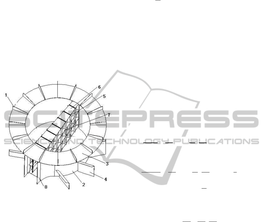
combined gas distributor. Shown in Figure 1, it is an
assembly of a twin-tangential annular flow vapour
horn (TTAF) and a shell vane inlet device (SV),
which was initially conceived to improve the gas
distribution quality of this special situation. A
computational fluid dynamics (CFD) approach was
developed to simulate the gas phase distribution in
431
Luo X., Sun J., Ren J., Gao H., Li L. and Pan C..
CFD Simulation of a Large-diameter Combined Gas Distributor.
DOI: 10.5220/0004427304310437
In Proceedings of the 3rd International Conference on Simulation and Modeling Methodologies, Technologies and Applications (SIMULTECH-2013),
pages 431-437
ISBN: 978-989-8565-69-3
Copyright
c
2013 SCITEPRESS (Science and Technology Publications, Lda.)
such combined gas distributor. Detailed systemic
data, including gas distribution and pressure drop,
was obtained to describe the gas flow that passed
through the combined distributor and the upper
space. The visible outcomes were then harnessed for
structural optimizations.
As to investigate the initial gas distribution and
considering the low liquid load of packed column,
no counter current liquid was considered in this
study. Such method has been also adopted in the
published literature (Fan et al., 1997),
(Haghshenasfard et al., 2007), (Zhang et al., 2004).
Figure 1: Structure of the combined gas distributor. 1 —
web plate; 2 —inside cylinder; 3 —annular channel; 4 —
baffle; 5 —vane; 6 —connecting plate; 7 —joint plate; 8
—flapper.
2 MATHEMATICAL MODEL
AND SOLUTION
2.1 Model Equations
A CFD modelling approach is basically solving
momentum conservation equations for a
computational domain. In this work, under the
condition of uncompressible gas flow and in the case
that user-defined source terms were not considered,
the flow governing equations can be simply written
as follows(Versteeg and Malalasekera, 1995):
Continuity equation:
ρ
0
(1)
Momentum equation:
∂
∂t
ρ
∙
ρ
P
∙μμ
ρ
(2)
where ρ is local fluid density, U is the velocity
vector, P is the pressure, μ is the viscosity, μ
t
is the
turbulent viscosity and g is the gravity acceleration.
The fluid was designated to be air with the density
ρ1.225kg/m
and the viscosityμ1.79895
10
kg/m∙s.
The standard k-ε model has been extensively
used to describe the turbulence in gas distributors
(Dhotre and Joshi, 2007), (Mohammadkhah and
Mostoufi, 2009), (Zhang et al., 2004). Considering
the physics encompassed in the flow, the level of
accuracy required and the time simulation, the
standard k-ε model, which is recognized to be sound
and valid in the range of Reynolds numbers for
turbulences with intensities from low to moderate,
was adopted.
For k
∂ρku
∂x
∂
∂x
μ
μ
σ
∂k
∂x
G
ρε
(3)
For ε
∂ρku
∂x
∂
∂x
μ
μ
σ
∂ε
∂x
C
G
ε
k
C
ρ
ε
k
(4)
The generation of turbulence kinetic energy, G
k
, can
be computed by:
G
μ
∂u
∂x
∂u
∂x
∂u
∂x
(5)
The constants for the standard k-ε model are
assigned as C
1.44,
1.92,
0.09,
1.0,
1.3
2.2 Computational Domain
and Mesh Generation
The CFD simulation was completed for the case of a
Ф6200 mm diameter column with inlet diameter of
Ф3000mm, as illustrated in Figure 2. Considering
the space limit in the packed column in industrial
application, the gas distribution on the horizontal
plane which is 1.2m above the annular plane of the
gas distributor was investigated. For the symmetric
structure of the gas distributor and the column, only
half of the column was simulated.
According to Tu et al. (Tu et al., 2008), the use
of hybrid grids can be provided maximum flexibility
SIMULTECH2013-3rdInternationalConferenceonSimulationandModelingMethodologies,Technologiesand
Applications
432

in the complex flow region. As a result, for our case,
the tetrahedral meshes in the gas distribution region
were created by the pre-processor GAMBIT2.4, and
the hexagonal grids were adopted in the rest
volumes, which are shown in Figure 3. The total
number of cells in the computational domain was
427, 020.
Figure 2: Computational Domain of the CFD simulation.
Figure 3: The grid map of the CFD simulation.
2.3 Boundary Conditions
To solve the equations of continuity and momentum,
appropriate boundary conditions should be specified,
as presented in Figure 2. Velocity-Inlet was adopted
as the gas inlet boundary, and the velocity,
turbulence intensity and hydraulics diameter were
set to 30m/s, 5% and 3m, respectively. The gas
outlet boundary was specified to be the Pressure-
Outlet, and the outlet pressure was set to 101,325Pa.
All walls were specified as no-slip wall boundaries.
The standard wall function method was used to
account for the near regions in the numerical
computation of turbulent flow. In addition, at the
plane of symmetry, the normal velocity is zero and
the gradients of the other variables in the transverse
coordinate direction are taken to be zero.
Some assumptions were used to simplify the
problem. They are as follows(Haghshenasfard et al.,
2007):
–The system is under steady-state conditions.
–The temperature is kept constant.
–The physical properties of the gas flow (air) are
constant throughout the column.
– The gas flow at the inlet section of the gas
distributors is uniform.
– Phenomena such as flow channelling and back
mixing can be neglected in the CFD models.
2.4 Numerical Method
The model in our work was solved by virtue of the
commercial package FLUENT 6.3.26 (Fluent Inc.,
USA). In the case of non-high speed and
incompressible fluid flow, we chose the segregated
solver, which had less memory requirement. The
convective terms in the governing equations were
modelled with the first-order upwind scheme. The
pressure-velocity coupling was obtained by using of
the SIMPLE algorithm with default under-
relaxations factors. During the simulation progress,
the convergence criteria for the residuals, including
x-velocity, y-velocity, z-velocity, k, and ε, were set
to 0.0001. The calculations of this work were
performed on a Dell PC with an Intel Core i7 CPU
and 4GB RAM.
3 RESULTS AND DISCUSSION
3.1 Grid Independence
To confirm that the simulation results are
independent of the grid size, the simulations results
of pressure drop were compared, which were
obtained from cells of 427020, 634809 and 1585497.
The pressure drop, ΔP, was defined as the pressure
difference between the inlet and the outlet.
ΔPP
P
(6)
As shown in Table 1, the pressure drop varies
slightly when the cell number is more than 427,020.
Considering the cost of computation, 427,020 cells
are appropriate for this simulation and the results
can be considered grid independent.
Table 1: Effect of cell number on pressure drop.
Cell number 427,020 634,809 1,585,497
ΔP (Pa) 1053 1089 1099
CFDSimulationofaLarge-diameterCombinedGasDistributor
433

3.2 Pressure Drop
and Mal-distribution
The mal-distribution factor (M
f
) represents the
ability of the distributing device to equalize the gas
flow, which is used as a parameter to estimate the
uniformity of the gas velocity parameter (Petrova et
al., 2003). It is evaluated at a certain horizontal
plane in the column at the height of 1.2m above the
annular channel, with the following equation:
M
1
n
U
U
U
(7)
where n is the total number of the sample points, U
i
is the local gas velocity at every point, and U
0
is the
superficial gas velocity, which is defined as the
average gas velocity of the investigated plane. The
sample points are shown in Figure 4. As the mal-
distribution factor decreases, it leads to a uniform
distribution of gas flow in the columns(Olujic et al.,
2003a).
Figure 4: Distribution of the sample points.
Figure 5: The simulation result of pressure drop at
different inlet velocities.
The pressure drop and mal-distribution at different
inlet velocities are shown in Figure 5 and Figure 6,
respectively. The pressure drop becomes larger as
the inlet velocity increases, whereas the mal-
distribution remains constant as the inlet velocity
varies from 10m/s to 70m/s. This regularity indicates
that the performance of the combined gas distributor
lies in the structure itself rather than in the inlet
velocity in this range.
Figure 6: The simulation result of mal-distribution factor
at different inlet velocities.
3.3 Effect of Width of the Annular
Channel
The width of the annular channel, w, observably
influences the performance of the combined gas
distributor. Figure 7 and Figure 8 show the pressure
drops and mal-distribution factors at different widths
of the annular channel, respectively. Both pressure
drop and mal-distribution, evidently, are small when
the width falls from 400 mm to 800 mm.
Specifically, when the width is less than 400 mm,
the outside flow path is too narrow for the gas flow,
leading to a large pressure loss in the front of the
combined gas distributor, consequently worsening
the distribution. In contrast, when the annular tunnel
is wider than 800 mm, the sectional area of the flow
path is squeezed to increase the gas flow resistance
greatly, worsening the gas distribution as well. By
comparison, 500 mm is considered the optimal
width of the annular channel.
Figure 7: Effect of the width of the annular channel on
pressure drop.
SIMULTECH2013-3rdInternationalConferenceonSimulationandModelingMethodologies,Technologiesand
Applications
434

Figure 8: Effect of the width of the annular channel on
pressure drop and mal-distribution factor.
3.4 Effect of Split Ratio
The two parts of the combined gas distributor, TTAF
and SV, have advantages and disadvantages. TTAF
is not appropriate for large-diameter inlets because
of the abrupt change in the flow cross-sectional area;
SV is also not appropriate because of its narrow
entrance. Thus, the split ratio of the inlet gas flow,
μ
io
, is an important factor that influences the
performance of the distributor.
The split ratio is controlled by the exact position
of the flappers, and the corresponding relation of the
two factors is shown in Table 2.
The effect of the split ratio on pressure drop is
shown in Figure 9 and the effect on mal-distribution
factor is in Figure 10. An unremarkable effect of
split ratio is gained by analysing. However, the
increasing split ratio caused a decreased pressure
drop and the same mal-distribution factor with
respect to widening the annular channel. When the
split ratio was 4, the performance of the gas
distributor was optimal.
Table 2: split ratios at different inlet flapper positions.
Distance between the two
flappers (mm)
Split ratio
1000 0.755
1200 1.047
1400 1.438
1600 1.985
1800 2.790
2000 4.061
2200 6.295
Figure 9: Effect of split ratio on pressure drop.
Figure 10: Effect of split ratio on mal-distribution factors.
4 STRUCTURAL
IMPROVEMENTS
Figure 11 shows the velocity vector in the column.
The low speed regions and vortexes upon the
annular channel, as well as the high speed zone of
the inside path above the distributor, are shown. The
abrupt change in the sectional area on the top of the
distributor is the primary factor that influences the
performance of the distributor.
According to the analysis above, six kinds of
structural improvements were proposed, as shown in
Figure 12.
All types of structural improvements, determined
by CFD analysis, improved the performance of the
distributor. The optimization comparisons of the
pressure drop and the mal-distribution factors for
every type of improvement are listed in Table 3. It
can be recognized that the effects of the six
variations are all positive. The structure patterns of d
and f result in the best mal-distribution factors, while
the f and g patterns have the greatest benefit on the
pressure drop. In summary, the structure f can be
CFDSimulationofaLarge-diameterCombinedGasDistributor
435

considered as the best structure pattern among the
six variations.
Table 3: Pressure drop and Mal-distribution of different
structure patterns.
Structure ΔP(Pa) Fall(%) M
f
(-) Fall(%)
Prototype a 1053 - 1.446 -
Structure b 977 7.2 1.322 8.7
Structure c 834 20.7 0.946 34.6
Structure d 842 20.0 0.831 42.5
Structure e 825 21.6 0.899 37.8
Structure f 782 25.7 0.833 42.6
Structure g 771 26.8 0.863 40.3
Figure 11: Velocity vector in the column (the column
diameter is Ф6200 mm and the inlet diameter is Ф3000
mm).
5 CONCLUSIONS
This work presents a three-dimensional CFD model
based on the novel combined gas distributor of a
large diameter, which integrates of a Twin-
Tangential Annular Deflector Gas Distributor and a
Two-Line Vane Gas Distributor. The gas distributor
was investigated numerically, where the pressure
drop and mal-distribution factor were adopted to
assess the uniformity of the gas distribution in the
columns. According to the CFD analysis, the mal-
distribution factor is hardly affected by the inlet
velocities. In addition, the gas distribution was found
to be the most uniform when the width of annular
channel was 500 mm and the split ratio was 4 for a
Ф6200 mm column.
According to the CFD results, six types of
structural improvements were suggested, which
were able to improve the uniformity of gas flow in
the column, and the type which remove the annular
channel from the prototype has been confirmed as
the best type among the six. These improvements
provide guidance for the further optimization of the
design of gas distributors.
Figure 12: Structural improvements.
SIMULTECH2013-3rdInternationalConferenceonSimulationandModelingMethodologies,Technologiesand
Applications
436

SYMBOLS USED
C
1ε
[-] model constant
C
2ε
[-] model constant
C
μ
[-] model constant
g [m·s
-2
] acceleration of
gravity
G
k
[kg · m
-1
· s
-1
] production of
turbulent kinetic
energy
k [m
2
·s
-2
] turbulent kinetic
energy
M
f
[-] mal-distribution
factor
n [-] number of sample
points
P [Pa] pressure
ΔP [Pa] pressure drop
t [s] time
U [m·s
-1
] interstitial velocity
U
i
[m·s
-1
] local velocity
U
0
[m·s
-1
] superficial velocity
w [mm] width of the annular
channel
Greek symbols
ε [m
2
·s
-3
] turbulent energy
dissipation
ρ [kg·m
3
] density
μ [kg·m
-1
·s
-1
] viscosity
μ
t
[kg·m
-1
·s
-1
] turbulent viscosity
μ
io
[-] split ratio
σ
k
[-] model constant
σ
t
[-] model constant
Ф [mm] diameter
Subscripts
i, j coordinate index
in inlet
out outlet
REFERENCES
Cai, T. J., Chen, G. X., Fitz, C. W. & Kunesh, J. G. 2003.
Effect Of Bed Length And Vapour Maldistribution On
Structured Packing Performance. Chemical
Engineering Research & Design, 81, 85-93.
Dhotre, M. T. & Joshi, J. B. 2007. Design Of A Gas
Distributor: Three-Dimensional Cfd Simulation Of A
Coupled System Consisting Of A Gas Chamber And
A Bubble Column. Chemical Engineering Journal,
125, 149-163.
Fan, L., Chen, G., Constanzo, S. & Lee, A. 1997.
Hydraulic Performance Of Gas Feed Distribution
Devices. Icheme Symp Ser.
Fitz, C. W., King, D. W. & Kunesh, J. G. 1999. Controlled
Liquid Maldistribution Studies On Structured Packing.
Chemical Engineering Research & Design, 77, 482-
486.
Haghshenasfard, M., Zivdar, M., Rahimi, R. & Esfahany,
M. N. 2007. Cfd Simulation Of Gas Distribution
Performance Of Gas Inlet Systems In Packed
Columns. Chemical Engineering & Technology, 30,
1176-1180.
Lockett, M. J. & Billingham, J. F. 2003. The Effect Of
Maldistribution On Separation In Packed Distillation
Columns. Chemical Engineering Research & Design,
81, 131-135.
Mohammadkhah, A. & Mostoufi, N. 2009. Effect Of
Geometry Of The Plenum Chamber On Gas
Distribution In A Fluidized Bed. Industrial &
Engineering Chemistry Research, 48, 7624-7630.
Olujic, Z., Ali, A. M. & Jansens, P. J. 2003a. Effect Of
The Initial Gas Maldistribution On The Pressure Drop
Of Structured Packings. Chemical Engineering And
Processing, 43, 465-476.
Olujic, Z., Kaibel, B., Jansen, H., Rietfort, T., Zich, E. &
Frey, G. 2003b. Distillation Column
Internals/Configurations For Process Intensification.
Chemical And Biochemical Engineering Quarterly,
17, 301-309.
Petrova, T., Semkov, K. & Dodev, C. 2003. Mathematical
Modeling Of Gas Distribution In Packed Columns.
Chemical Engineering And Processing, 42, 931-937.
Stoter, F., Olujić, Ž. & De Graauw, J. 1993. Modelling
And Measurement Of Gas Flow Distribution In
Corrugated Sheet Structured Packings. The Chemical
Engineering Journal And The Biochemical
Engineering Journal.
Tu, J., Yeoh, G. H. & Liu, C. 2008. Computational Fluid
Dynamics -A Practical Approach, Amsterdam,
Elsevier Inc.
Versteeg, H. K. & Malalasekera, W. 1995.
An
Introduction To Computational Fluid Dynamics: The
Finite Volume Method, New York, Wiley.
Wehrli, M., Hirschberg, S. & Schweizer, R. 2003.
Influence Of Vapour Feed Design On The Flow
Distribution Below Packings. Chemical Engineering
Research & Design, 81, 116-121.
Zhang, L. H., Zhou, H. Y., Li, X. G. & Du, Y. P. 2004.
Cfd Analysis Of Gas Distributor In Packed Column -
Prediction Of Gas Flow And Effect Of Tower
Internals Geometry Structure. Transactions Of Tianjin
University, 10, 270-274.
CFDSimulationofaLarge-diameterCombinedGasDistributor
437
