
Inter-module Communications for Rear-end Collision Avoidance
Messaging in an IEEE 802.11p Interface
Juan-Bautista Tomas-Gabarron, Esteban Egea-Lopez and Joan Garcia-Haro
Department of Information and Communication Technologies, Universidad Politecnica de Cartagena
Plaza del Hospital, 1, 30202 Cartagena, Spain
Keywords:
NCTUns, Event-driven, CCA, VANET.
Abstract:
Computer simulation is thepreferred approach when investigating Vehicular Ad-hoc Networks (VANET). Dur-
ing the last years different platforms have emerged, regarding the evaluation of next-generation autonomous
vehicular mobility and car-to-car wireless connectivity. NCTUns (now Estinet) is a relevant networking plat-
form that provides support for IEEE 802.11p-based connectivity between vehicles. This paper describes the
implementation of an inter-module communications’ scheme in NCTUns designed to allow reciprocal mes-
sage transmission and processing between a mobility and a messaging agent in vehicles supporting Coopera-
tive chain Collision Avoidance (CcCA) for improving safety even under rear-end collision risky circumstances.
Contributions hold in the bidirectional inter-module channel that features the management of mobility in these
environments according to the communication’s protocol that implements the CcCA application, and vicev-
ersa. As an additional characteristic of the implementation, a Nakagami-m channel model is implemented to
recreate intervehicular communications more realistically.
1 INTRODUCTION
Network simulators are nowadays essential tools for
the design, development and evaluation of commu-
nication protocols. The importance of simulation is
due primarily to the fact that it allows developers to
carry out experiments using a model-based approach
that saves time and money. It also gives them much
more flexibility than real experiments, since it can be
used for example to evaluate network performance
under different configurations with remarkable easi-
ness. Simulation results are also easier to handle due
to the great simplicity when directly collecting and
processing digital data.
Network simulators, however, have some limita-
tions. A functional network simulator needs to sim-
ulate network devices (eg. routers and hosts) and ap-
plications that generate network traffic. It is also nec-
essary to provide monitoring programs and set up the
configuration parameters for each test. These facts
mean that network simulators work according to a
model of reality whose functionality might not corre-
spond entirely with the real processes that it recreates.
The associated drawbacks are summarized next:
• Network simulator results are not, for obvious
reasons, as realistic as those obtained in real ex-
periments under the same circumstances, since to
limit the complexity and production costs, most
network simulators implement simplified versions
of reality (network protocols), that usually lead to
results that do not necessarily match physical phe-
nomena in most situations.
• Most network simulators do not have the prop-
erty of extensibility because they are exempt from
supporting the UNIX POSIX API
1
. As a result,
existing network applications as well as those yet
to be developed can not be executed properly to
generate traffic for a given simulated network un-
der different OS, nor can evaluate its performance
under different network settings. On the con-
trary, they make use of the API provided by the
own simulator and are compiled with it to build a
unique, modular and quite complex program that
only works in the same computer where compila-
tion takes place.
To avoid these problems, the NCTUns/Estinet
team (Shie-Yuan and Chih-Che, 2008) devised a sim-
1
Family of standards which implements a common
framework of system calls for extensive compatibility be-
tween different operating systems (see reference (Board,
1999)).
82
Tomas-Gabarron J., Egea-Lopez E. and Garcia-Haro J..
Inter-module Communications for Rear-end Collision Avoidance Messaging in an IEEE 802.11p Interface.
DOI: 10.5220/0004427500820089
In Proceedings of the 3rd International Conference on Simulation and Modeling Methodologies, Technologies and Applications (SIMULTECH-2013),
pages 82-89
ISBN: 978-989-8565-69-3
Copyright
c
2013 SCITEPRESS (Science and Technology Publications, Lda.)
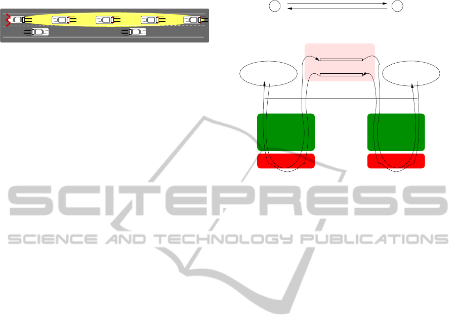
any influence in our scenario
Vehicles 6 and 7 do not have
and sends warning notification messages
Vehicle 5 collides with an obstacle
to vehicles located behind it in the lane
Vehicles 4, 3, 2 and 1 receive
notification messages from vehicle 5
and start to brake
6
7
4 3 2 15
Figure 1: Simulation scenario with 802.11p communication
capabilities.
ulation methodology called kernel reentering, which
was already used in the first version of the simulator,
called Harvard NS. Later, some significant improve-
ments were made to the original methodology to fi-
nally implement the simulator and emulator capabil-
ities that NCTUns currently supports. By using the
technique of kernel reentering, NCTUns provides a
number of advantages over traditional simulators that
will be thoroughly explained in next subsections of
this Introduction.
For a more practical view of the characteristics
of NCTUns and focusing on the particular imple-
mentation of intervehicular connectivity in VANETs,
we describe in the second section of this paper the
core implementation of our inter-module communi-
cations’ scheme, i.e. the specific functionality of our
CcCA application. Since NCTUns addresses mo-
bility and communications as independent processes,
we had to implement a specific two-way communi-
cations’ scheme to allow both of them to work to-
gether in general collision avoidance applications.
This way it is possible to establish safety policies to
reduce the probability of accident in rear-end colli-
sion avoidance scenarios like that of Fig. 1 by al-
lowing information exchange for mobility update, and
viceversa. Furthermore, making use of the WSMP
(WAVE Short Message Protocol) for a more efficient
message transmission methodology, as well as the
Nakagami model for radio signal propagation, we
introduce in depth the main characteristics of our
scheme. Actually, this extension has proved flexi-
ble and has been succesfully used to evaluate VANET
performance in various scenarios (see (Garcia-Costa
et al., 2012), for example). Implementation codes
and installation guides are available on the Internet
at www.juanbatomas.com.
We will finish this paper by making some allu-
sions to the utility of this scheme and possible future
worklines of this implementation.
1.1 Kernel Reentering Methodology
Using a tunnel network interface is the basic approach
that summarizes the functionality offered by the reen-
tering simulation methodology of NCTUns. A tunnel
TCP sender
TCP/IP
stack
TCP/IP
stack
Interface 1 Interface 2
TCP receiver
LINK 1
LINK 2
Simulation Engine
User−level
Kernel
Link 2
Link 1
TCP receiverTCP sender
Host 2Host 1
Figure 2: Kernel reentering methodology of NCTUns.
network interface available on most UNIX machines,
is a pseudo network interface that does not have any
physical network interface assigned to it. However,
the functionality of this interface is not different from
the one offered by the Ethernet network interface, i.e.
an application program to send and receive packets on
this pseudo network interface would offer the same
functionality as if it did through a physical interface.
Each tunnel interface has a special device file as-
signed to it, which any application running on NC-
TUns has access to, basically for writing information
related to packets that are sent to other network en-
tities for the purpose of simulation. From the per-
spective of the kernel module, the packet seems to
come from an external communications network, and
will come trough the TCP/IP protocol stack just like
normal Ethernet packets would do (Shie-Yuan and
Chih-Che, 2008). Moreover, if an application pro-
gram reads a packet from the special device file of the
tunnel interface, the first packet in the output queue
of the kernel tunnel interface will be copied to the ap-
plication program. This situation is interpreted by the
kernel as if a packet had been sent to a real link with-
out knowing if this transmission had taken place with
real Ethernet packets (see Fig. 2).
1.2 Main Characteristics of NCTUns
In the following list we present the most important
features that characterize NCTUns as a network sim-
ulation platform, and the reasons we use to justify its
choice as our simulation environment for implement-
ing the rear-end collision avoidance scheme (CcCA).
• Thanks to the Kernel reentering methodology of
NCTUns, this platform can use the UNIX pro-
tocol stack in its own network interface for the
Inter-moduleCommunicationsforRear-endCollisionAvoidanceMessaginginanIEEE802.11pInterface
83

generation of very realistic results. By the time
we carried out the implementation of our bidi-
rectional module, the WSMP protocol was not
supported by the Linux Kernel yet, so we had
to use the application-layer version of this pro-
tocol that came along with the general API of
the platform. Now that preliminary versions of
the WAVE stack are already supported in differ-
ent linux-based platforms, it is possible to design
applications relying on communication stacks im-
plementing functional versions of the WSMP pro-
tocol (see for example (Hernandez-Jayo et al.,
2012)).
• In NCTUns real UNIX applications can be used
as traffic generators (teletraffic) for network per-
formance evaluation. In our case, we will make
the implementation of a specific application based
on the timely transmission of chain collision alerts
(CcCA).
• It is possible to use configuration tools and real
network monitoring services such as ifconfig, net-
stat, tcpdump, traceroute, etc. available on all
UNIX operating systems. In our case we will use
a diagnostic tool designed exclusively by us, since
our main concern is not to analyze the teletraffic
utilizing the network, but until to which extent ve-
hicle’s safety can be improved.
• NCTUns supports the simulation of a wide vari-
ety of different types of network protocols and
network devices. In our case we simulate a Ve-
hicular Ad-hoc Network for emergencybraking in
CcCA (with the protocol stack architecture WAVE
1609/IEEE 802.11p).
• Due to the discrete event simulation approach of
NCTUns, simulation runs execute very quickly
(in the general case). Also, simulation results are
repeatable, thus bringingus the possibility of eval-
uating network performance under particular sce-
narios that might need further analysis.
Despite the plug-and-play methodology of NC-
TUns for the evaluation of linux-based user services,
this platform also suffers, in our opinion, from some
drawbacks that are mentioned next:
• Although NCTUns is open source, it contains a
proprietary GUI (Guided User Interface) that the
end user can not modify. This somewhat reduces
the flexibility of the programmer to set up com-
plex scenarios and develop new protocols.
• NCTUns does not provide general simulation
scripts for the automatic setup of network config-
uration files. Normally, it is necessary to make
a great effort to program a series of Bash/Python
scripts that were used to set up network parame-
ters in the VANET under consideration.
• The WSMP protocol we use for the transmission
of information in the network layer of the WAVE
architecture is not implemented in the Linux ker-
nel. This implies that the advantage of directly
using the TCP/IP stack from the network interface
(basically, the reentering methodology) is lost due
to the fact that WSMP is simulated as if it was a
process of the application layer.
• The generation of a large number of sockets (for
each virtual interface, each one for each vehicle)
to perform simulations and the deficient memory
release scheme of NCTUns when a simulation
ends, specially after making a remarkable deal
of system simulations, occasionally implies that
the socket creation process takes longer time than
simulating the network under consideration.
• The NCTUns network simulator suffers from a
drawback that could negatively reduce the num-
ber of potential users: the lack of an API (Appli-
cation Project Interface) documenting all the code
generated for the networking platform, greatly in-
creases the programmer’s effort to understand the
functionality offered by the simulator. Actually,
authors had to investigate the details of the code
without having a sufficiently clear description of
the architectural implementation of the NCTUns
modules.
Fortunately, all these issues have already been
solved by offering a commercial version of NCTUns,
renamed Estinet, which provides the same function-
ality of NCTUns, but includes a very useful docu-
mentation of the API that greatly reduces the effort
of the network programmer. Whatsoever, it has be-
come commercial, thus requiring to pay a license that
might decrease the number of potential new users.
NCTUns, on the other hand, can still be found (in
its original open source version) for download in
http://nsl.csie.nctu.edu.tw/nctuns.html.
2 CcCA COMMUNICATIONS
MODULE FOR NCTUns
Once we have presented the most important features
of NCTUns, we describe the main module imple-
mented to support communications in applications for
the transmission of chain collision alerts.
In the present case, we differentiate between two
complementary modules:
• Mobility Module: although NCTUns already in-
cludes the implementation of different types of
SIMULTECH2013-3rdInternationalConferenceonSimulationandModelingMethodologies,Technologiesand
Applications
84

mobility models, in our case we developed our
own motion dynamics for vehicles circulating in
convoy under risk of chain collision. We preferred
to do this because already available mobility man-
agers in NCTUns are designed to govern vehicu-
lar motion on preestablished roads which must be
configured beforehand in the setup files. In our
case, we are not interested in completing a certain
path marked by a road, but analyzing howvehicles
can react when following dynamical routes ac-
cording to the reaction to Cooperative chain Col-
lision Avoidance (CcCA) notifications received in
destination.
• Communications Module: Although not im-
plemented in the Linux kernel (like the TCP/IP
stack), NCTUns allows us to use WSMP (WAVE
Short Message Protocol) as an application service
(instead of a network layer implementation) for
the transmission of safety information between
vehicles. Because of the timing requirements set
by this safety-related application, using this pro-
tocol is advisable in this case. In this context it is
necessary to carry out some internal modifications
of the original WSMP module
2
in order to enable
a bidirectional link between the communications
module and the mobility module, as we will see
next.
In our study, the implementation of two-way com-
munication between the two modules is required,
mainly for the following reasons:
• In a hypothetical situation where a vehicle col-
lides with an obstacle along its path it is necessary
to notify the communications module that it has
the responsibility for sending information to the
following vehicles (in the form of WSMP pack-
ets) in order to warn them about this event.
• In the same situation, if a vehicle receives WSMP
packets, a reaction to this information is foreseen.
This requires informing both the communications
module and the mobility module, so that the lat-
ter can respond to the received information by, for
example, reducing the vehicle speed as appropri-
ate.
All vehicles will contain these two modules,
coded by using the NCTUns APIs and the UNIX
sockets libraries that hold the generic functionality
of the AF
UNIX sockets, available for implementing
communications between different processes on the
same machine.
2
The one that came already installed in the NCTUns dis-
tribution.
Figure 3: System’s state diagram.
2.1 Mobility Module
Due to the enormous complexity of developing mo-
bility models for generic vehicular traffic, we focus
on a particular implementation of a mobility model
that is adapted to the specific situation of emergency
braking for CcCA. Fig. 3 represents the different tran-
sition states that each vehicle can contemplate during
motion, whereas Fig. 4 shows a flowchart with the be-
havior of each vehicle according to the specific traffic
state in which it might be found, and the particular
update of state variables that takes place.
All vehicles will behave according to five possible
states:
1. Basic Circulation: the vehicle moves at a con-
stant speed along its path on the road.
2. Reaction to Brake: in a normal braking situation
(human assistance), the driver will need a small
time interval (between 0.5 and 1 s) to start to slow
down (from the moment the danger is noticed un-
til the brake pedal is pushed).
3. Braking: once the brake pedal is pressed (in hu-
man assisted driving) or due to automatic braking
in an autonomous driving scheme, the vehicle be-
gins to decelerate so as to reach null speed in the
driveway.
Inter-moduleCommunicationsforRear-endCollisionAvoidanceMessaginginanIEEE802.11pInterface
85

4. Vehicle Collided: the vehicle does not stop in
time to avoid a collision with the vehicle ahead.
5. Vehicle Stopped Successfully: the vehicle has
successfully managed to stop and therefore it
avoided the collision.
As can be seen in the flowchart presented in Fig.
4, first we configure a set of parameters that represents
the essential characteristics of mobility of vehicles in
this particular scenario: initial driving direction, ini-
tial position and initial speed. In our implementa-
tion this is achieved by the API implemented in NC-
TUns for developing user-specific mobility agents, by
means of a socket communication scheme that allows
sending mobility management commands to the sim-
ulation engine (which handles mobility).
Then we can observe the logical loop that deter-
mines the mobility patterns of the designed model
(see the corresponding state’s diagram in Fig. 3).
First we evaluate whether the speeds of all vehicles
are equal to zero. In this case, the simulation ends to
avoid consuming more time. Afterwards it calculates
for each vehicle the position of the nearest neighbor
in the direction of transit (either ahead or rear). If the
distance is less than a certain threshold, we consider
this to be a collision, so a variable that stores the state
of the vehicle (specifically colEvent) is set to 1 (0 oth-
erwise). In the following step we analyze the value of
this variable. If it is equal to 1, it means that the ve-
hicle is in a state of collision, thus we tell the process
governing the mobility of the collided vehicle to stop
to save simulation resources. We simply set the vehi-
cle speed to zero and advance the simulation time.
If the vehicle is found in a normal traffic state,
that is, neither stopped (by braking successfully with-
out colliding), nor collided, first we evaluate whether
there is any message in the mobility queue. Because
in our case the only sent message corresponds to alert
emergency braking, there is no problem in terms of
packet prioritization. Particularly, all sudden brake
warning messages in this implementation contain the
following information:
• Position of the collided vehicle that issued the
alert: to be used to check whether it is possible
to stop in time.
• Timestamp at which the message was sent: to
check end to end delay of messages.
• Damaged vehicle identifier: to verify the identity
of the vehicle that was involved in the accident.
Should we find such messages in the mobility
queue, the receiving vehicle automatically calculates
the braking distance that it needs to reach a full stand-
still stop, according to the equation presented below,
obtained from reference (de Fomento., 2011):
Figure 4: Communications’ module flowchart.
D
p
=
v
I
·t
p
3.6
+
v
2
I
254(i+ f
i
)
(1)
Where v
I
denotes the initial speed in km/h, i the
SIMULTECH2013-3rdInternationalConferenceonSimulationandModelingMethodologies,Technologiesand
Applications
86

road slope coefficient, t
p
the sum of the perception
and the reaction time, and f
i
representing the longi-
tudinal friction coefficient. The resulting distance (in
meters) will be the sum of the distance traveled by the
vehicle during the reaction time (first term) and the
distance traveled while braking (second term). In our
case, we skip the first term in the calculation of D
p
,
since we will only consider that the stopping distance
is calculated from the time instant the vehicle starts
to brake (the reaction time is also taken into account,
but not for the calculation of D
p
). As we can see,
the relationship between speed and braking distance
is squared, implying that two times the speed requires
a braking distance multiplied by four. Another im-
portant factor to consider is the road friction, if f
i
is
very low due to poor conditions of wheels or because
of bad weather conditions, the stopping distance may
increase considerably, in fact on a icy pavement (e.g.
f
i
= 0.05, on a plane surface i=0) a car could have a
stopping distance of a mile approximately at an aver-
age speed of 100 km/h.
In the case in which the vehicle finds no queued
messages in the mobility queue, it checks whether
there is any standing obstacle ahead on the road that
could become a potential risk of accident. If a vehi-
cle discovers an obstacle blocking the road along its
path of movement, it will start to brake. If it collides,
it will set the speed to zero, simulating the accident,
and send an alert information to upcoming vehicles.
Now it will transition to the collision status.
The last part of the algorithm corresponds to a sit-
uation where a particular vehicle begins to brake to
avoid colliding with the vehicle directly ahead, ei-
ther because of a too high speed differential, or due
to the reception of accident warning notifications. In
this case, according to our braking model, we as-
sume that the vehicle decelerates with a speed that
decreases linearly with time (constant braking decel-
eration). Due to the specific implementation of the
NCTUns process manager (to switch between differ-
ent machine processes and advance the simulation
time), in our program we have to necessarily set an
idle time (S) that the core engine of NCTUns uses to
advance in the simulation time (during which the mo-
bility/communication processes remain asleep). For
this purpose, we have derived a mathematical equa-
tion that provides the speed of the vehicle at any time
after starting the braking process, regardless of the
time duration of the idle period. The expression is:
v(t
k
) = v(t
k−1
) −
v
2
(t
k−1
)
2D
p
·
t
k−1
+
S
2
− t
stop
ρ
(2)
Where v(t
k
) denotes the speed to be set at the cur-
Assignment points
for the average speed
Speed (m/s)
Position (m/s)
Initial
position
Stopping location
after successfully
Real speed
Computed speed
Initial
speed
braking
process sleeps)
(period while the
(braking distance)
S
D
p
Figure 5: Idle-time period graph for the calculation of speed
during braking.
rent instant k, according to the speed at the previous
instant (k−1) v(t
k−1
), the pre-calculated braking dis-
tance D
p
, the idle time interval of the application (for
advancing the simulation time) S, the time at which
the emergency braking begins t
stop
, and the scaling
factor of the simulation time ρ (t
k
and t
stop
are ex-
pressed in ticks, i.e. simulator time units, with a par-
ticular equivalence in temporal units: in our program
we configure it to be 1 tick = 100 ns).
The derivation of the above expression is ex-
plained below. Due to the linear decrease of speed, it
will become a value at a future instant which is gov-
erned by the expression:
v(t
k
) = v(t
k−1
) − a·t
lapse
(3)
Since the vehicle will need D
p
meters (according
to our mobility model) to fully stop, the followingsys-
tem of equations holds:
v
I
− a· T = 0
v
I
· T − a ·
T
2
2
= D
p
(4)
This system can be understood by realizing that
when braking for a time interval of T s (time required
to fulfill a complete stop), the car will reach zero
speed. Moreover, the second equation expresses the
distance D
p
that is covered during the braking pro-
cess. If we solve the system of equations we obtain a
value for the acceleration that takes the expression:
a =
v
2
I
2D
p
(5)
Substituting in the first term we have:
v(t
k
) = v(t
k−1
) −
v
2
I
2D
p
·t
lapse
(6)
To give value to t
lapse
let us carefully observe Fig.
5, which represents the evolution of the speed from
the moment the vehicle begins to slow down until it
completely stops.
Inter-moduleCommunicationsforRear-endCollisionAvoidanceMessaginginanIEEE802.11pInterface
87

As we can see, the simulation engine will dispatch
the mobility manager every S time units (ticks), in or-
der to advance the simulation time. Each time the mo-
bility agent is awaken the simulation time will have
advanced a time lapse of S ticks, thus needing to con-
veniently update the speed. However, due to the linear
decrease of speed until the vehicle stops, the mobility
manager must establish a constant moving speed dur-
ing the interval when the process sleeps that allows to
cover the same distance as if the speed was updated at
infinitesimal time periods. Because of that, for obvi-
ous reasons we take the speed at the midpoint of each
interval of S ticks. This makes t
lapse
take the value
given by the following expression:
t
lapse
=
t
k
+
S
2
− t
stop
· S (7)
Substituting Eq. (7) in the second equation of the
System (4) we will get the value of the speed for suc-
cessive instants.
All vehicles will start moving at an average speed
that will be one of the representative configuration pa-
rameters in simulations. The intervehicular distance
will also play an important role in the simulation,
since the greater the distance the lower the probability
of incurring in chain accidents. Moreover, the trans-
mission power will be decisive on the behavior of ve-
hicles reacting to the reception of warning messages,
since it will influence on the end to end delay as well
as other performance metrics like throughput.
2.2 WSMP Communications’ Module
The communications module WSMP (WAVE Short
Message Protocol) implements the network layer pro-
tocol of the architecture WAVE, using a simplified
packet format that reduces overhead for a more effi-
cient packet transmission and processing. This mod-
ule is already implemented in the NCTUns 6.0 ver-
sion we used for simulations, although in the context
of our particular application for CcCA, it was nec-
essary to carry out some modifications of the code
to support bidirectional communications between this
protocol and the mobility manager. Particularly, we
have defined logical parallel threads to implement
bidirectional communication between both modules.
As regards functionality, the WSMP module con-
stantly awaits (when control of the simulation engine
is given to the machine processes) the reception of:
• Messages sent by other vehicle reporting a partic-
ular issue about traffic safety (specifically, a colli-
sion ahead).
• Messages from the mobility management module
within the same vehicle, reporting a particular fea-
ture of the nearby traffic, because it might have
found an obstacle ahead. Therefore, it must in-
form the other nodes that come behind to conve-
niently react to this situation.
By implementing these changes in the WSMP
module, the system can support bidirectional com-
munication between both the communication and the
mobility management modules, allowing us to build
our own mobility model supporting active behavior
in CcCA according to the reception of warning mes-
sages.
2.3 Nakagami-m Radio Propagation
Model for the Communication’s
Channel
The propagation model that is used to recreate the
characteristics of the physical layer in a simulation
platform plays a decisive influence on the simulation
speed and the reliability of results. Probabilistic mod-
els usually reproduce more faithfully the features of
the associated signal propagation process in vehicular
environments, even though they require more compu-
tational processing resources compared to determin-
istic models like the Two-Ray Ground or Free Space
(Sizun and de Fornel, 2004). Particularly, the Nak-
agami model is frequently used for modeling such
propagation effects in simulation platforms. Due to
the wide variety of simulation approaches using Nak-
agami as channel model, and thanks to the trade-off
between a great reliability when reproducing real-
world propagationphenomena,and a reasonable com-
puter processing cost of results, the use of this model
in such scenarios is justified. Actually, this model can
be used to model signal propagation in different sce-
narios, by controlling the value of its main design pa-
rameter m, as we will see later. In fact, for the im-
plementation of our design we use the values of m
extracted from the reference (Torrent-Moreno et al.,
2004).
The Nakagami model is highly generic. The re-
ception power follows a gamma distribution, as seen
in Eq. (8):
P
r
(d;m) ∼ γ
m,
P
r
det
(d)
m
(8)
The m parameter specifies the intensity of the at-
tenuation effects on signal transmission process. Its
main purpose is to configure the type of scenario of
operation (low values of m, environments with higher
losses, like urban environments; high values of m,
environments with lower attenuation losses like mo-
torways). P
r
det
corresponds to the calculation of
SIMULTECH2013-3rdInternationalConferenceonSimulationandModelingMethodologies,Technologiesand
Applications
88

the received power value for a deterministic propaga-
tion model like Free Space or Two-Ray Ground (see
(Sizun and de Fornel, 2004)).
3 CONCLUSIONS
AND FUTURE WORK
This work presents the implementation of an
application-layer module for the NCTUns network
platform that supports bidirectional communication
between a mobility and a communications process
working on the same protocol stack (of each vehi-
cle). This characteristic allows us to implement a
scheme where mobility can benefit from communi-
cations and viceversa for improved driving safety, in
particular, for Cooperative chain Collision Avoidance
(CcCA) support in two or more vehicles. In this re-
gard, the mobility module manages the car’s mobil-
ity and also collects information about the vehicle’s
dynamics (speed, position...). This collected informa-
tion is given to the communication’s module, which
according to the specific processing scheme, will de-
liver safety-related notification packets alerting about
a possible risk in the neighboring car traffic. On the
other hand, the communication’s module implements
the functionality as related to the exchange of infor-
mation packets between vehicles. When received at
destination (based on a broadcast approach), packets
are processed to extract interesting information that
could be useful to avoid possible crashes by helping
vehicles execute timely braking maneuvers.
We additionally solve some implementation as-
pects concerning the introduction of the bidirectional
communications scheme between the mobility and
the communications’ modules by fixing the asyn-
chronous distributionof simulation time for the differ-
ent processes (mobility and communications) acting
on top of the communications’ stack of each partici-
pating vehicle. This paves the way for more complex
applications to be implemented in this platform that
may use the bidirectional mobility-communications’
scheme to support road safety enhancements.
As future work, we plan to extend the function-
ality of the supported application in the bidirectional
communications’ scheme by also implementing eva-
sive maneuvering for collision avoidance policies.
Actually, a recently published algorithm for this type
of collision avoidance scenarios has been developed
by the Authors (Tomas-Gabarron et al., 2013), giving
promising results, which now can be structured in an
application in NCTUns in order to assess the perfor-
mance of the communicationprocess in this particular
implementation.
ACKNOWLEDGEMENTS
This work was supported by project grant
MINECO/FEDER TEC2010-21405-C02-02/TCM
(CALM). It was also developed in the framework of
’Programa de Ayudas a Grupos de Excelencia de la
Regi
´
on de Murcia, Fundaci
´
on S
´
eneca’. J. B. Tomas-
Gabarron also thanks the Spanish MICINN for a FPU
(REF AP2008-02244) pre-doctoral fellowship.
REFERENCES
Board, I.-S. S. (1999). Ieee standard for informa-
tion technology-portable operating system interface
(posix)-part 1: System application program interface
(api)- amendment d: Additional real time extensions
[c language].
de Fomento., M. (2011). Trazado. instrucci´on de carreteras.
norma 3.1-ic.
Garcia-Costa, C., Egea-Lopez, E., Tomas-Gabarron, J.,
Garcia-Haro, J., and Haas, Z. (2012). A stochastic
model for chain collisions of vehicles equipped with
vehicular communications. Intelligent Transportation
Systems, IEEE Transactions on, 13(2):503 –518.
Hernandez-Jayo, U., Sainz, N., Iglesias, I., Elejoste, M.,
Jimenez, D., and Zumalde, I. (2012). Ieee802.11p
field operational test implementation and driver as-
sistance services for enhanced driver safety. In Con-
sumer Communications and Networking Conference
(CCNC), 2012 IEEE, pages 305 –310.
Shie-Yuan, W. and Chih-Che, L. (2008). Nctuns 5.0: A
network simulator for ieee 802.11(p) and 1609 wire-
less vehicular network researches. In Vehicular Tech-
nology Conference, 2008. VTC 2008-Fall. IEEE 68th,
pages 1 –2.
Sizun, H. and de Fornel, P. (2004). Radio Wave Propagation
for Telecommunication Applications. Foundations of
Engineering Mechanics Series. Springer.
Tomas-Gabarron, J., Egea-Lopez, E., and Garcia-Haro, J.
(2013). Optimization of vehicular trajectories under
gaussian noise disturbances. Future Internet, MDPI,
(5):1–20.
Torrent-Moreno, M., Jiang, D., and Hartenstein, H. (2004).
Broadcast reception rates and effects of priority access
in 802.11-based vehicular ad-hoc networks. In Pro-
ceedings of the 1st ACM international workshop on
Vehicular ad hoc networks, VANET ’04, pages 10–18,
New York, NY, USA. ACM.
Inter-moduleCommunicationsforRear-endCollisionAvoidanceMessaginginanIEEE802.11pInterface
89
