
A Robust Design for Image-based Visual Servoing
Hajer Abidi
1
, Khaled Kaaniche
1,2
, Hassen Mekki
1,2
and Mohamed Chtourou
1
1
Control and Energies Management Laboratory, University of Sfax, Sfax, Tunisia
2
National School of Engineering of Sousse, University of Sousse, Sousse, Tunisia
Keywords: 2D Visual Servoing, Robust Design, Matching, SURF, PROSAC.
Abstract: In this paper we introduce a new robust visual scheme intended to 2D visual servoing robotic tasks. The
main object is to direct the robot to its desired position. To be able to carry out such a task robustly the
tough and major step is primarily the image processing procedure. We should find good selections of visual
data in order to be correctly matched and interpreted by the visual control law regardless of the different
sorts of errors. The new proposed design combines the speed up robust features (SURF) algorithm and
progressive sample consensus (PROSAC) algorithm to accomplish a good feature extraction and to rapidly
resist the environment constraints while removing the erroneous matches.
1 INTRODUCTION
Vision-based robotic tasks termed visual servoing by
(Hutchinson et al., 1996) has known a prominent
advancement and has been employed in many fields:
from military and medical applications to
automotive areas. The idea of using visual data as an
entry promotes the autonomy of the system.
However many accuracy problems may occur
because of camera calibration errors and
environment uncertainties.
In order to build a stable and a robust control
law, the visual feedback should be the result of a
robust, efficient and real time data processing. Thus,
robust techniques have to be utilized in order to
determine the system references.
Related works in this field have shown the
presence of two sorts of vision description in visual
servoing: global and local description (Abidi et al.,
2012). The global descriptors principle is to consider
the entire image as input for the system. Global
features could be for example the image luminance
(Collewet et al., 2010) or the selection of random
pixel luminance sets (Hammouda et al., 2012) also
the mutual information between a current and a
desired image (Viola and Wells, 1997). Despite their
advantage of discarding the tracking and matching
steps they still suffer from a high computation time
and a definite divergence when considering large
initial displacements. In the other hand local
descriptors came to deal with global techniques
issues.
Lowe, 2004, developed a scale and rotation
invariant algorithm (SIFT) which targets the
characterization of the image interest points by
gathering both a detector and a descriptor. This
algorithm has proved highly-efficient and
outperforming the current state of art in visual
control schemes. The (SIFT) moments (Nierobisch
et al., 2007) have also been used and tested on a 6
DOF KATANA manipulator with an eye-in-hand
camera. The visual servoing scheme relies on
robustly-matched geometric moments which could
resist occlusions and view point changes. Another
derivative of (SIFT) called (PCA-SIFT) (Ke and
Sukthankar, 2004) which seems to be faster than its
predecessor but more sensitive to registration
problems.
The complexity of these techniques has entailed
a high computational time and therefore they seem
to be very slow. SURF algorithm developed by Bay,
2006, came to fill this gap with a greatly- reduced
computing time. This algorithm contains basically a
detector to extract interest points and a descriptor of
64 dimensions to depict each single point. It is also
invariant to image scale and rotation transformations
and deal with many sorts of environment changes.
Melting speed and robustness, (SURF) could
lead to a successful recognition task nevertheless
when talking about robotic tasks with real life issues
like blur, high illumination changes, and occlusions
the mismatching probability increases which may
generate the failure of the visual servoing task.
Therefore, we need a method that guarantees a stable
139
Abidi H., Kaaniche K., Mekki H. and Chtourou M..
A Robust Design for Image-based Visual Servoing.
DOI: 10.5220/0004428301390146
In Proceedings of the 10th International Conference on Informatics in Control, Automation and Robotics (ICINCO-2013), pages 139-146
ISBN: 978-989-8565-70-9
Copyright
c
2013 SCITEPRESS (Science and Technology Publications, Lda.)

and correct matching that can be ensured with
PROSAC (Chum and Matas, 2005). This technique
allows the extraction of good correspondences by
ordering the matched points according to a similarity
function and not randomly in order to show up
features from progressively larger sets. This method
is not so far from the random sample consensus
RANSAC algorithm (Fischler and Bolles, 1981)
considered as a robust matching technique; the only
difference is that RANSAC handles the samples
uniformly and randomly. The progressive behavior
beginning with high ranked matches makes
PROSAC more efficient and a hundred times as fast
as RANSAC.
The contribution of this paper consists on a
robust design to avoid the system failure which is
originally due to the closed loop injected outliers.
Therefore, in this paper we will stress the utility of
SURF in the extraction stage and PROSAC to cope
with the infiltrated matching errors nay in presence
of complex environment constraints. The design
experimented and implemented on a mobile robot
model can provide robust entries to the visual
servoing system and lead to joining successfully and
accurately the desired position.
This paper is organized as follows: section II
provides an explanation of the major constraints
opposing the 2D visual servoing robotic tasks. Due
to the limitation of existing feature extraction
techniques, a robust visual servoing design is
proposed in section III based on a combination of an
efficient image processing and statistics techniques.
As to section IV, it demonstrates the simulation
experiments applied on a 3 DOF eye-in-hand mobile
robot model.
2 THE SYSTEM CONSTRAINTS
A visual servoing task is based at first on a
recognition system to provide useful data for the
control law such as points, lines or more complex
structures. Figure 2 shows the basic steps of
recognition. After being matched, features
considered as inliers are going to be used as input
for the visual servoing system. The control law aims
to reduce a minimization criterion:
e
t
= fp,r
t
- f
*
(1)
Where e is the error between a set of visual features
f
r
captured at each camera pose ′r′ and their
desired position f*. p presents the system parameters
like the intrinsic camera or the object model
parameters. Since f depends on the time variation we
can write:
∂f
∂t
=
∂f
∂x
∂x
∂t
(2)
f
=L
f
V
(3)
V=(v,w) is the camera velocity (v is the linear
velocity and w is the angular velocity). L
f
is the
interaction matrix attached to f that links the time
variation of a set of current features to the camera
motion.
If we consider that the desired position is fixed,
we obtain:
e=L
e
V
(4)
For an exponential decoupling decrease of the error
(Comport, 2006):
e=-λe
(5)
Using (4) and (5), we deduce that the control law
can be defined as follows:
V=-λL
e
+
e
(6)
L
e
+
is the estimation of the pseudo-inverse of the
interaction matrix.
Le=
-
1
Z
0
x
Z
xy -
1+x
2
y
0
-1
Z
y
Z
1+y
2
-xy -x
(7)
Z is an estimation of the depth relative to the camera
frame and V is the robot controller entry.
x=
X
Z
=
u-pu
γF
y=
Y
Z
=
v-pv
γF
(8)
Where (X, Y, Z) are the world coordinates of a point
expressed in the camera frame and (x,y) are the
projected image plan coordinates. (u,v) are the point
coordinates expressed in pixel, (pu,pv) are the
coordinates of the perspective image plan central
point, F is the focal length and γ is the ratio of a
pixel size.
We can see the important number of parameters
that should be estimated at each camera pose.
Besides, we note the projection in the image plane
yielding a significant loss of accuracy. Furthermore,
we should mention the presence of noise, occlusion
(static and dynamic), and natural phenomena such as
shadows, reflections, darkness and illumination
changes.
According to the control law expression, we can
see that the error value could be easily influenced by
ICINCO2013-10thInternationalConferenceonInformaticsinControl,AutomationandRobotics
140

Figure 1: A flowchart of a robust visual design for visual servoing robotic tasks.
Figure 2: Description of the principle stages related to a
recognition process.
these anomalies, that’s why we are trying in this
paper to show how to cope with these problems and
robustly extract our system entries.
3 ROBUST FEATURE
PROCESSING
The proposed architecture is based firstly on fast and
efficient interest cues detection by using SURF
detectors and descriptors. Secondly, a robust
matching verification and outlier elimination is
established through the PROSAC algorithm. A
homography matrix is estimated so that good
matches could be selected in every camera motion.
Afterwards, an interaction matrix called image
Jacobian, is built to create the robot control
translational and angular velocities (Figure 1
illustrates the different steps of the proposed design).
3.1 Feature Extraction with SURF
A study done by (Juan and Gwun, 2009) has proved
the efficiency of the SURF algorithm compared with
other robust algorithms like SIFT and PCA-SIFT.
This algorithm is mainly known for its calculation
speed and its robustness to illumination changes.
SURF has two main steps; the first one is to detect
the image interest points and the second one is to
describe these points. To save time, the captured
image is transformed into an integral image (Viola
and Jones, 2001) because of its fastness to deal with
convolution computations. Next, we seek for the
areas that have high pixel intensity changes. Interest
points are, therefore, located where we find a
maximal Hessian matrix determinant. Since the
Hessian matrix is based on second order partial
derivatives which are going to be computed by a
convolution with Gaussians, an approximation with
a function called the “box filter” seems useful to
guarantee more rapidity for the system.
The Hessian matrix is calculated as follows:
H
x,σ
=
L
xx
x,σ
L
xy
x,σ
L
yx
x,σ
L
yy
x,σ
(9)
Where L
xx
x,σ
, L
yy
x,σ
and L
xy
x,σ
are a
convolution of the Laplacian of Gaussian with the
integral image in x.
A representation to a lower scale levels is
obtained by raising the size of the Gaussian filters.
Eventually, the points with a positive Hessian matrix
determinant, and which are local maxima in a
neighborhood 3 x 3 x 3 (representing x, y and scale)
are kept. Once the interest points are extracted,
descriptors should be assigned.
Visual features
extraction with
SU
RF
PROSAC
robust matching
Robust
Visual
samples
Controller
Mobile Robot + Camera
Error
measure
Data extraction
Robust matching and outlier elimination
Minimisation
criterion
Visual servoing control
Visual data
acquisition
Desired image
coordinates
Current image
coordinates
-
+
ARobustDesignforImage-basedVisualServoing
141
The SURF descriptor describes the intensity of
pixels in a neighborhood around each point. The
response for x and y Haar wavelets (dx anddy) is
calculated in a neighborhood of 6 scales at which an
interest point was found. From these values, the
dominant orientation of each interest point is
calculated by sliding an orientation window. A
descriptor is obtained by extracting a square of size
20 scales directed along the dominant orientation.
This area is also divided into 4x4 squares. For each
of these sub-areas, the Haar wavelets are computed
for 5x5 points.
Finally four values are calculated for each sub-
region (
∑
dx,
∑
dy,
∑|
dy
|
,
∑|
dy
|
) and each extracted
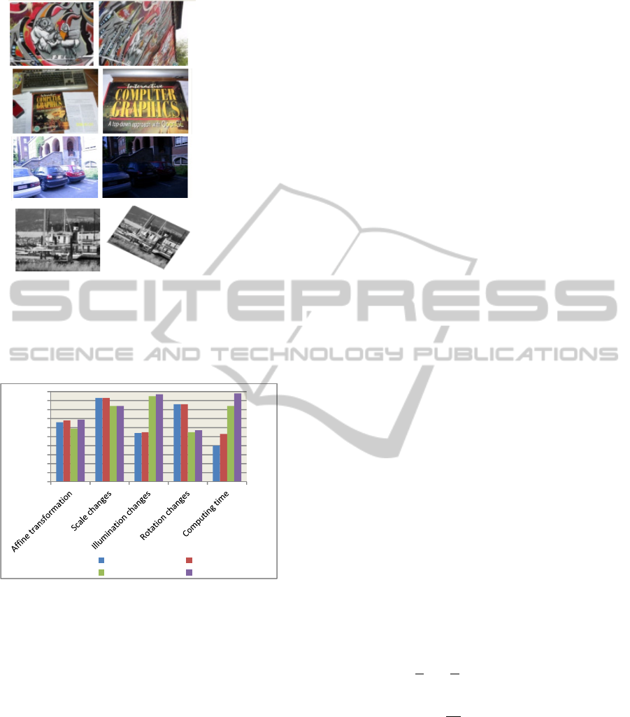
point is described by a 4x4x4 vector (length 64). In
Figure 4, we found an example of feature extraction
using SURF.
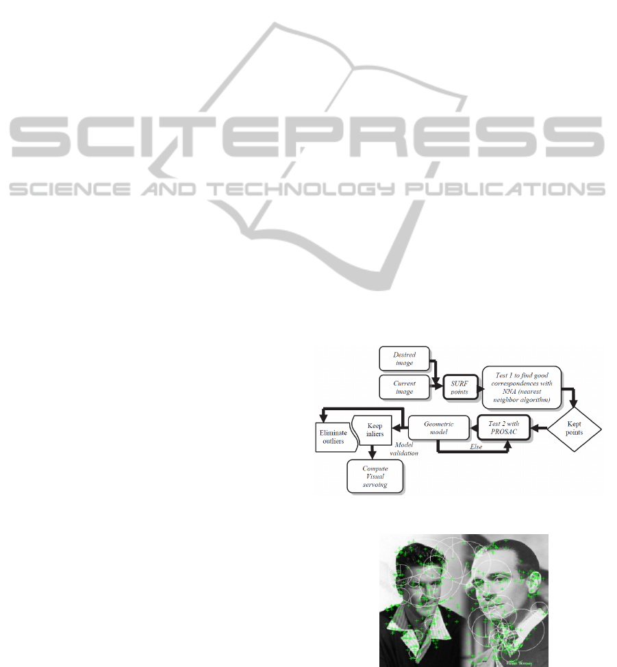
3.2 Matching with PROSAC
In practice, the erroneous matching induces the
divergence of the controlled system. Thus, we can’t
rely only on good descriptors. A powerful outlier
elimination method is necessary so that we can
succeed in moving the robot to its desired position.
In the proposed design (Figure 1) we are looking for
more accuracy by applying a derivative of RANSAC
called PROSAC which is a much more efficient and
rapid. The fact that all matches are not necessarily
equaled, PROSAC gradually progresses toward a
uniform sampling. A thresholding of a similarity
function allows to pick out the ordered samples. The
PROSAC technique is based on progressively larger
subsets of top-ranked correspondences leading to
computational savings (Chum and Matas, 2005).
To outline, PROSAC assesses samples to follow
a quality decreasing order. The lowest quality sets
are treated in a second place. The algorithm can be
summarized in the following steps:
step1/ In order to estimate a geometric model,
PROSAC does not select randomly a set of samples
but an order of magnitude is rather considered.
step2/ It searches for elements called inliers that
may validate the model.
step3/ If there is not enough inliers, the algorithm
returns to 1/, else the model is validated.
step4/ After a fixed number of testing, the algorithm
stops.
According to the proposed design, PROSAC
would estimate the homography matrix using robust
matches in every captured image.
H=
h
11
h
21
h
31
h
12
h
22
h
32
h
13
h
23
h
33
(10)
We suppose:
p
c
=
x
c
y
c
1
p
d
=
x
d
y
d
1
(11)
p
is the coordinate of an interest point in the
desired position and p
depicts the current position
coordinates:
p'=
γx
c
γy
c
γ
=H p
d
(12)
A good model estimation could guarantee an
efficient matching for the entered samples. In Figure
3, we found a more detailed representation of the
new matching system.
3.3 Comparison to other Robust
Techniques
It is obvious that researches dealing with visual
servoing robustness problems head predominately
the powerful algorithms in vision, control and
planning fields. As we are focusing to solve visual
issues, we found in (Marquez-Neila et al, 2008) a
method to locate planar landmarks involving
RANSAC to eliminate outliers.
This technique targets mobile robots navigation.
Also in (Song et al., 2010) RANSAC was
Figure 3: Robust outliers remove technique.
Figure 4: Example of feature extraction using SURF.
ICINCO2013-10thInternationalConferenceonInformaticsinControl,AutomationandRobotics
142
(a)Affine
transformation
(b)Scale
changes
(c)Illumination
changes
(d)Rotation
changes
Figure 5: Evaluation images taken from INRIA database
(Juan, 2009): the first sample (a) presents the affine
transformation of the image, the second one (b) indicates
the scale changes, the third sample (c) is about
illumination changes and the final one (d) points out the
rotation changes.
Figure 6: Matching efficiency percentage of some robust
feature detection techniques.
used to upgrade SIFT visual cues for grasping tasks.
Furthermore, SIFT features mixed with geometric
3D lines were used in (Lee, Kim and Park, 2006) to
enhance certainty in 3D recognition.
After being established, SURF came to defeat
these techniques notably when talking about the
huge computational cost and high illumination
changes. We have used different images sweeping
different environment phenomena (Figure 5). As
seen in Figure 6, we can’t make conclusions about
the entire efficiency of one technique but we can
infer that SURF+PROSAC show a stable behavior
by making a balance between the most visual
constraints with 84% of matching efficiency in
presence of scale changes, 97% when having
changes in illumination and a fast processing speed
with an efficiency percentage of 98%. We notice
that computational time has been improved in all the
cases due to PROSAC. SIFT+RANSAC or
SIFT+PROSAC show also a good performance
especially for rotation changes with 86% and scale
changes with 93% but they still suffer from a very
low computational time ranging between 40 and
53%.
4 EXPERIMENTS AND RESULTS
In this section experiments were applied on a two
wheel eye-in-hand “Koala” mobile robot model with
a CCD camera. In each test case the robot has as
entry a desired pose defined as follows:
∗
∗
∗
(13)
According to this position desired visual cues are
extracted using our visual design from the
corresponding captured image I
∗
. When a
displacement is applied the robot is conducted to a
random position and respectively the new current
features must be defined. Primarily we begin with a
robust identification and description using SURF
algorithm. Second we try to compute similitude
between desired and current references using
Euclidian distance. When correspondences are found
PROSAC establishes a descending matching order
starting with sets of most confident cues. The
considered order yields to a fast successful
matching. To control the robot motion velocities
should be calculated using the control law described
previously in (6). In this case the computed
interaction matrix for each interest point is:
Le=
(14)
=
-
1
Z
x
Z
-
1+x
2
(15)
0
(16)
The elements of
and
correspond to the
translation along x and z axis and the rotation
according to yaxis.
Simulations have been tested with virtual reality
modeling language (VRML). For the first
experiment we took as initial positioning error:
Δ
r
=
11 cm, 13cm, 0.12 rad
in presence of 40%
of illumination changes.
0
10
20
30
40
50
60
70
80
90
100
SIFT+RANSAC SIFT+PROSAC
SURF+RANSAC SURF+PROSAC
ARobustDesignforImage-basedVisualServoing
143

Figure 7(a) and Figure 7(b) show the current and
desired positions captured by the camera. Figure
7(c) presents the initial difference between the two
images. Curves in Figure 7(d) and 7(e) depict a
smooth decreasing to zero of ∆
, ∆
and ∆
even
when illumination conditions were changed. Figures
7(f), 7(g) and 7(h) show that the translational robot
velocities V
x
and V
z
and the rotational velocity Θ
applied to the robot reach zero within only 70
iterations.
The same experiment was remade using
RANSAC instead of PROSAC. Simulation results in
Figure 8(a) and Figure 8(b) show that the
positioning error reached zero in a much longer
time.
(a) (b) (c)
(d) (e)
(mm/s)
(mm/s)
/
(f) (g) (h)
Figure 7: The positioning error variation using our robust
visual servoing design (the abscissa axis indicates the
iteration number): (a) the current camera pose and (b) the
desired camera pose. (d) The translational error (∆
Tx
and
∆
Tz
) expressed in meter (m). (e) The rotational error ∆
Θy
expressed in radian (rad). (f, g and h) The robot velocities.
(a) (b)
Figure 8: The positioning error variation using
SURF+RANSAC during the same experimental
conditions. (a) The translational error ∆
Tx
and ∆
Tz
in meter
(m). (b) The rotational error ∆
Θy
in radian (rad).
The system takes 400 iterations to converge
toward its desired position. Figure 9 emphasizes the
presence of two mismatches during the visual
servoing task when RANSAC has been applied
hereas in this case PROSAC proved a correct match
for the same camera displacements.
In the second experiment we have tested scenes
with different textures and in presence of
illumination, rotation and scale changes. Table 1
presents the variation of the positioning errors
relative to the frame number. We can see that the
translational and rotational errors tend to zero for all
the cases which means that the system converges
robustly to its desired position.
The curve (2.c) of the second case when a
rotation change has been applied shows that the
system takes 700 frames to attain a global error
norm equal to zero. In case of scale variation with a
depth error of 50 cm, 350 frames were needed to
reach the desired position however in the first case
only 80 frames have been captured before
convergence. Thus we notice the efficiency of the
proposed system against many significant changes in
scale, rotation and especially illumination.
(a)
(b)
Figure 9: Example of matching between a current and
desired pose. (a) Matching using RANSAC (presence of
two mismatches in yellow lines). (b) Matching using
PROSAC for the same camera pose.
5 CONCLUSIONS
The melting of the Speed up robust features and
progressive sample consensus algorithms in a visual
servoing design reflected a satisfying behavior. A
notably improvement of the system performance
was obvious with a smooth decreasing of positioning
errors in presence of constraints like illumination,
rotation and scale changes. Experiments with virtual
0 10 20 30 40 50 60 70
-0.02
0
0.02
0.04
0.06
0.08
0.1
0.12
0 10 20 30 40 50 60 70
0
0.02
0.04
0.06
0.08
0.1
0.12
0.14
0.16
0 10 20 30 40 50 60 70
-0.3
-0.2
-0.1
0
0.1
0.2
0.3
0.4
0.5
0.6
0 10 20 30 40 50 60 70
-1.2
-1
-0.8
-0.6
-0.4
-0.2
0
0.2
0 10 20 30 40 50 60 70
-0.8
-0.6
-0.4
-0.2
0
0.2
0.4
0.6
0 50 100 150 200 250 300 350 400 450
-0.0 2
0
0.02
0.04
0.06
0.08
0.1
0.12
0.14
0 50 100 150 200 250 300 350 400 450
0
0.02
0.04
0.06
0.08
0.1
0.12
0.14
∆
∆
∆
∆
∆
∆
ICINCO2013-10thInternationalConferenceonInformaticsinControl,AutomationandRobotics
144

0 10 20 30 40 50 60 70 80 90
0
1
2
3
4
5
6
7
8
x 10
7
0 10 20 30 40 50 60 70 80 90
-0.02
-0.018
-0.016
-0.014
-0.012
-0.01
-0.008
-0.006
-0.004
-0.002
0
0 100 200 300 400 500 600 700 800
-0.15
-0.1
-0.05
0
0.05
0.1
0.15
0.2
0.25
0 10 0 200 300 400 500 600 700 800
0
0.05
0.1
0.15
0.2
0.25
0.3
0.35
0 100 200 300 400 500 600 700 800
0
0.5
1
1.5
2
2.5
3
3.5
4
x 10
7
0 50 100 150 200 250 300 350 400
0
1
2
3
4
5
6
7
8
x 10
7
0 50 100 150 200 250 300 350 400
-0.02
-0.01
0
0.01
0.02
0.03
0.04
0.05
0.06
0 50 100 150 200 250 300 350 400
-0.5
-0.4
-0.3
-0.2
-0.1
0
0.1
0.2
0 10 20 30 40 50 60 70 80 90
-0.05
0
0.05
0.1
0.15
0.2
0.25
0.3
reality modeling environment confirm the
convergence of the control law in many cases and
with diverse image textures. The new proposed
design is able to guide the robot successfully and
robustly to its desired position and ensure an
important time saving. A future work aims to
enhance the existing system in order to defeat all the
external environment constraints and strengthen the
robotic task convergence.
Table 1: Experimental results with different image textures: ((1.a) and (1.b)) translational (cm) and rotational (rad)
positioning errors corresponding to brightness changes. ((2.a) and (2.b)) Translational (cm) and rotational (rad) positioning
errors corresponding to rotation changes. ((3.a) and (3.b)) Translational (cm) and rotational (rad) positioning errors
corresponding to scale changes. ((1, 2 and 3.c) The global error norm.
Case 1: Brightness change
(Positioning error : ∆
Tx
=23 cm, ∆
Tz
=17 cm)
(1.a)
(1.b) (1.c)
Case 2: Rotaion change
(Positioning error : ∆
Tx
=20 cm, ∆
Θy
=0.3 rad)
(2.a)
(2.b) (2.c)
Case 3: Scale change
(Positioning error : ∆
Tx
=5 cm, ∆
Tz
= -50 cm)
(3.a)
(3.b) (3.c)
∆
∆
∆
∆
∆
∆
∆
∆
∆
Global error norm
Global error norm
Global error norm
ARobustDesignforImage-basedVisualServoing
145

REFERENCES
Abidi, H., Mekki, H., Kaâniche, k., Chtourou, M., 2012.
An Overview Of The Robust Approaches Applied For
2D Visual Servoing. In 9th International Multi-
Conference on Signals and Device, pp. 1-6.Bay, H.,
Tuytelaars, T. and Van Gool, L., 2006. SURF:
Speeded Up Robust Features. In 9th European
Conference on Computer Vision, pp. 404-417.
Chum, O., Matas, J., 2005. Matching with PROSAC –
Progressive Sample Consensus. Proceedings of
Computer Vision and Pattern Recognition, pp. 220–
226.
Collewet, C., Marchand, E. and Chaumette, F., 2010.
Luminance: a new visual feature for visual servoing.
In Visual Servoing via Advanced Numerical Methods.
LNCIS 401, Springer-Verlag (Ed), pp. 71-90.
Comport, A. I., Marchand, E., Chaumette, F., 2006.
Statistically robust 2D visual servoing. IEEE
Transactions On Robotics, Vol. 22, pp. 415–421.
Fischler, M. and Bolles, R., 1981. Random Sampling
Consensus: a Paradigm for Model Ftting with
Application to Image Analysis and Automated
Cartography, Commun. Assoc. Compo, vol. 24, pp.
381-395.
Juan, L. and Gwun, O., 2009. A comparison of sift, pca-
sift and surf. International Journal of Image
Processing (IJIP), Vol. 65, pp. 143-152.
Hammouda, L., Kaâniche, K., Mekki, H., Chtourou, M.,
2012. Global visual features based on random
process: Application to visual servoing. Proceedings
of the 9th International Conference on Informatics in
Control, Automation and Robotics, pp. 105-112.
Hutchinson, S., Hager, G. and Corke, P., 1996. A tutorial
on visual servo control. IEEE Transactions on
Robotics and Automation, 12(5), pp. 651–670.
Ke, Y., and Sukthankar, R., 2004. A More Distinctive
Representation for Local Image Descriptors. Proc.
Conf. Computer Vision and Pattern Recognition, pp.
511-517.
Lowe, D., 2004. Distinctive Image Features from Scale-
Invariant Keypoints, IJCV, 60(2), pp. 91–110.
Lee, S., Kim, E. and Park, Y., 2006. 3D Object
Recognition using Multiple Features for Robotic
Manipulation. IEEE International Conference on
Robotics and Automation, pp. 3768–3774.
Marquez-Neila, P., Garcia Miro, J., Buenaposada, J.M.
and Baumela, L., 2008. Improving RANSAC for Fast
Landmark Recognition. In Proc. of Computer Society
Conference on Computer Vision and Pattern
Recognition, Anchorage, AK, pp. 1-8.
Nierobisch, T., Krettek, J., Khan, U. and Hoffmann, F.,
2007. Optimal Large View Visual Servoing with Sets
of SIFT Features. IEEE International Conference on
Robotics and Automation, pp. 10-14.
Song, K., Chang, Ch. and Lin, Ch., 2010. Robust Feature
Extraction and Control Design for Autonomous
Grasping and Mobile Manipulation. International
Conference on System Science and Engineering, pp.
445-450.
Viola, P., Jones, M., 2001. Rapid object detection using a
boosted cascade of simple features.
Proceedings of the
IEEE Computer Society Conference, Computer Vision
and Pattern Recognition, vol. 1, pp. 1-511.
Viola, P., Wells, W.M., 1997. Alignment by maximization
of mutual information. International Journal of
Computer Vision, 24, pp. 137–154.
ICINCO2013-10thInternationalConferenceonInformaticsinControl,AutomationandRobotics
146
