
Multi-Agent Systems for Evasive Maneuvers of Mobile Robots
through Agreements
Ángel Soriano, Enrique J. Bernabeu, Ángel Valera and Marina Vallés
Instituto Universitario de Automática e Informática Industrial, Universitat Politècnica de Valencia,
Camino de Vera s/n, 46022, Valencia, Spain
Keywords: Multi-Agent Systems, Collision Avoidance, Mobile Robot, Robot Control, Intelligent Systems.
Abstract: This paper presents a new methodical approach to the problem of collision avoidance of mobile robots
taking advantages of multi-agents systems to deliver solutions that benefit the whole system. The approach
proposed is based-on the information interchange among the involved agents. The implemented method has
the next phases: collision detection, obstacle identification, negotiation, agreement, and collision avoidance.
In addition of simulations with virtual robots, in order to validate the proposed algorithm, an
implementation with real mobile robots has been developed. The robots are based on Lego NXT, and they
are equipped with a ring of proximity sensors for the collisions detections. The platform for the
implementation and management of the multi-agent system is JADE.
1 INTRODUCTION
The area of artificial intelligence (AI) has expanded
considerably in recent years. It not only dominates
the area of games versus computers, but nowadays it
applies in many sectors like databases management
or web pages. As it is well known, the main topic of
AI is the concept of intelligent agent defined as an
autonomous entity which observes through sensors
and acts upon an environment using actuators
(Russell, 2009). This definition is very close to
services that a robot can provide, so the concept of
agent often is related with robots, (Bruce et al.,
1997), (van Leeuwen, 1995), (Michalewicz, 1996).
On the other hand, detecting and avoiding a
collision is a previous step for overcoming the
motion planning problem. In fact, collision detection
has been inherently connected with the motion-
planning algorithms from the very beginning.
Current planning algorithms require the collision
detection of mobile and nondeterministic obstacles.
Collision-detection techniques for mobile robots
and obstacles can be divided into discrete collision
detection (DCD), and continuous collision detection
(CCD).
The DCD algorithms involve stepping the
motion of both the mobile robot and the mobile
obstacle at a sample time rate. Collision tests are
then checked for such configurations. A recent
example is found in (Urmson et al., 2008).
Nevertheless, the DCD algorithms may miss a
collision between two consecutive configurations.
This problem, termed tunneling, is overcome by
using a dynamic time-step strategy (Schwarzer,
Saha, Latombe, 2005).
The CCD techniques are more effective because
motions are not stepped. CCD algorithms basically
make a return if a collision between the motion of
two given objects is presented or not; and if a
collision is going to occur then, the instant in time of
the first contact is returned (Schwarzer et al., 2005);
(Choi et al., 2006); (Redon et al., 2002); (Cameron,
1990); (Tang et al., 2009); (van den Bergen, 2005),
and (Bernabeu, 2009).
In this paper, local collision detection strategies
of autonomous mobile robots based on (Bernabeu et
al., 2001) are improved with artificial intelligence
and multi-agent coordination strategies to offer a
new method of collision avoiding management.
Two representative local collision-detection
methods are ORCA (van den Berg, et. al., 2011) and
DRCA (Lalish and Morgansen, 2008). These
methods estimate the velocities of the nearby objects
by means of a sensor system. In the presented work,
the information perceived by each agent or robot is
transmitted only to the in-sight agents using wireless
communications. Then, the collision avoidance
140
Soriano Á., J. Bernabeu E., Valera Á. and Vallés M..
Multi-Agent Systems for Evasive Maneuvers of Mobile Robots through Agreements.
DOI: 10.5220/0004430101400147
In Proceedings of the 10th International Conference on Informatics in Control, Automation and Robotics (ICINCO-2013), pages 140-147
ISBN: 978-989-8565-71-6
Copyright
c
2013 SCITEPRESS (Science and Technology Publications, Lda.)

technique in this paper combines local with quasi-
global strategies.
2 METHODOLOGICAL
APPROACH
This paper expects to present a new methodical
approach to the problem of collision avoidance of
mobile robots, taking advantages of multi-agents
systems (MAS) to deliver solutions that benefit the
whole system. The method is divided into three
basic concepts (see Figure 1) which are merged in
this paper: obstacle detection by a mobile robot, the
concept of abstraction robotic agent as a software
agent within MAS, and distributed artificial
intelligence as a method of communication and
negotiation between these software agents.
Figure 1: Diagram of the connection between concepts.
Nowadays, the obstacle detection by mobile
robots is not a new problem. In fact, there are many
sensors on the market that allow, with more or less
certainty, robots to know if there is an obstacle that
stands between them and its trajectory, and where is
that obstacle. This process is local, i.e. it is
performed inside the robot. In the case of two
mobile robots at the same scenario, each one
represents an obstacle to the other, but neither is
aware of it because it is handled as a local process.
Therefore, the concept of robotic agent in a multi-
agent robotic system is proposed as a next level or
upper layer to fix it and to manage a more intelligent
solution.
Multi-agent robot systems (MARS) represent a
complex distributed system, consisting of a large
number of agents-robots cooperating for solving a
common task. Each agent of MARS is an
independent system which manages subsystems like
tasks execution, perception of environment by
sensors, trajectory control, robots communications,
etc. In this case, each agent of MARS represents a
real physical mobile robot that informs its software
agent of all it perceives.
The ability of the MAS to provide intelligent
solutions in a distributed architecture is well known.
The ability of communication, cooperation and
coordination between the agents, allows
conversations, negotiations and deductions that local
system itself could not perform.
When a group of individual agents is involved in
a MAS, it is necessary a mechanism for the agents
coordination and communication. There are two
main coordination mechanisms: one for cases in
which the agents have common objectives and,
therefore, they have to cooperate, and in other cases
for which the agents are competitive and objectives
are conflicting with each other, for which purpose,
negotiation mechanisms are required (Huhns and
Malhotra, 1999); (Singh and Huhns, 1999). Some of
the negotiations mechanisms more used in the
literature are the coalition, market mechanisms,
bargaining theory, voting, auctions and allocation of
tasks between two agents. More specifically, for
automated negotiation techniques (Fatima et al.,
2001), (Rahwan et al., 2004) there are mainly three
ones, based on: game theory, heuristics and
argument.
Communications have a very important role
because negotiations depend directly on an effective
communication. There are different agent
communication languages (Austin, 1962); (Searle,
1969), FIPA-ACL (FIPA Agent Communication
Language) and KQML (Knowledge Query and
Manipulation Language).
In the development of methodologies for the
design of multi-agent systems, researchers have
focused their efforts on extending existing
methodologies. These extensions have been made
mainly on two areas: on the object-oriented
methodologies and on Knowledge Engineering
(Iglesias et al., 1999). A MAS is inherently
multithreaded, each agent has at least one thread of
control (Wooldridge, 2002). These characteristics
make the MAS particularly suitable for the
development of systems that operate in complex,
dynamic and unpredictable environments.
3 AVOIDING COLLISION
METHOD
The aim of this section is showing a review for
obtaining the instant in time when two robots or
agents in motion will be located at their maximum-
approach positions while they are following straight-
line trajectories (Bernabeu et al., 2001).
The mentioned maximum approach is also
calculated. Therefore, if the involved robots do not
collide while they are following their respective
motions, then their minimum separation is returned.
Otherwise, their maximum penetration is computed
Multi-AgentSystemsforEvasiveManeuversofMobileRobotsthroughAgreements
141

as a minimum translational distance (Cameron and
Culley, 1986).
A remarkable aspect is that both the instant in
time and the corresponding minimum separation or
maximum approach are computed without stepping
any involved trajectory.
Some collision avoiding configurations for the
involved robots or agents are directly generated from
the computed instant in time and maximum
penetration. These collision-free configurations are
determined in accordance with a given coordination
between the robots or agents.
3.1 Obtaining the Instant in Time
and the Maximum Approach
Consider two robots or agents in motion each one
enveloped or modeled by a circle. Let A be a circle
in motion whose start position at time t
s
is
A(t
s
)=(c
A
(t
s
),r
A
), where c
A
(t
s
)
2
is the A’s center at
t
s
and r
A
is its radius. A is following a straight-
line trajectory whose final position at t
g
is given by
A(t
g
)=(c
A
(t
g
),r
A
). Let v
A
2
be the A’s velocity for
the time span [t
s
,t
g
].
Let B be a second circle in motion whose start
and goal positions at the respective instants in time t
s
and t
g
are B(t
s
)=(c
B
(t
s
),r
B
) and B(t
g
)=(c
B
(t
g
),r
B
). The
B’s velocity for the
time span [t
s
,t
g
] is v
B
2
.
All the infinite intermediate positions of the
mobile circle A for t[t
s
,t
g
] while A is in motion is
parameterized by with [0,1], as follows:
))()((λ)()λ( :)),λ(()λ(
sAgAsAAAA
tctctccrc
A
(1)
and
. [0,1]λ ; )λ(
sgs
tttt
Note that the positions A() and A(t), with
t=t
s
+(t
g
t
s
), are equal for all t[t
s
,t
g
] and [0,1].
All the infinite intermediate positions of the mobile
circle B are analogously parameterized for [0,1]
as indicated in (1).
Observing equation (1) is easy to conclude that
the maximum approach d
M
between in-motion
circles A and B will be obtained by finding the
parameter
c
[0,1] that minimizes
)(||)λ()λ(||
BABA
rrcc
(2)
Once
c
is obtained, d
M
and the associated instant in
time t
M
are computed as
)(λ
)(||)λ()λ(||
sgcsM
BAcBcAM
tttt
rrccd
(3)
Note that d
M
might be negative. If d
M
is negative,
then d
M
holds a penetration distance and,
consequently A and B will collide and the maximum
penetration d
M
will be given at t
M
. If the maximum
approach, d
M
, is zero, then A and B will be in contact
at t
M
. Finally, if d
M
is strictly greater than zero, A and
B will not collide for t[t
s
,t
g
], being its minimum
separation d
M
at t
M
.
The parameter
c
[0,1] is simply obtained by
minimizing ||c
A
()c
B
()|| for all [0,1], i.e. by
computing the distance from the origin point O to
the straight-line c
A
()c
B
() (Bernabeu, Tornero,
Tomizuka, 2001). Graphically, the previously
explained distance computation is shown in Figure
2, in accordance with equation (1),
A B As Ag As
Bs Bg Bs
c(λ)c(λ)c(t)λ(c (t ) c (t ))
c(t)λ(c (t ) c (t ))
λ [0,1] .
(4)
Operating:
ABAsBs
Ag Bg As Bs
c(λ)c(λ) c (t ) c (t )
λ ((c (t) c (t)) (c (t) c(t))
λ [0,1] .
(5)
Note that c
A
()c
B
() for all [0,1] is really a
segment whose extreme points are respectively
c
A
(t
s
)c
B
(t
s
) and c
A
(t
g
)c
B
(t
g
). These points are now
referred to as c
0
=c
A
(t
s
)c
B
(t
s
) and c
1
=c
A
(t
g
)c
B
(t
g
).
Then, the parameter
c
[0,1] is obtained by
projecting O onto mentioned segment, O
, as
. ]1,0[λ with
||||
)(
λ
2
01
010
cc
cc
ccc
(6)
The projected O
is then
)(λ
010
cccO
c
(7)
If the obtained
c
verifies
c
[0,1], then the instant
in time when A and B will be located at their
maximum approach positions is out of the given
time span [t
s
,t
g
].
In case of collision, the positions where A and B
present their maximum penetration are, as
mentioned, c
A
(
c
) and c
B
(
c
) respectively. One of
these positions can be minimally translated in order
to bring both circles into contact by using the unit
vector
MTD
v
ˆ
, with
1||
ˆ
||
MTD
v
,
.
||||
ˆ
O
O
v
MTD
(8)
ICINCO2013-10thInternationalConferenceonInformaticsinControl,AutomationandRobotics
142
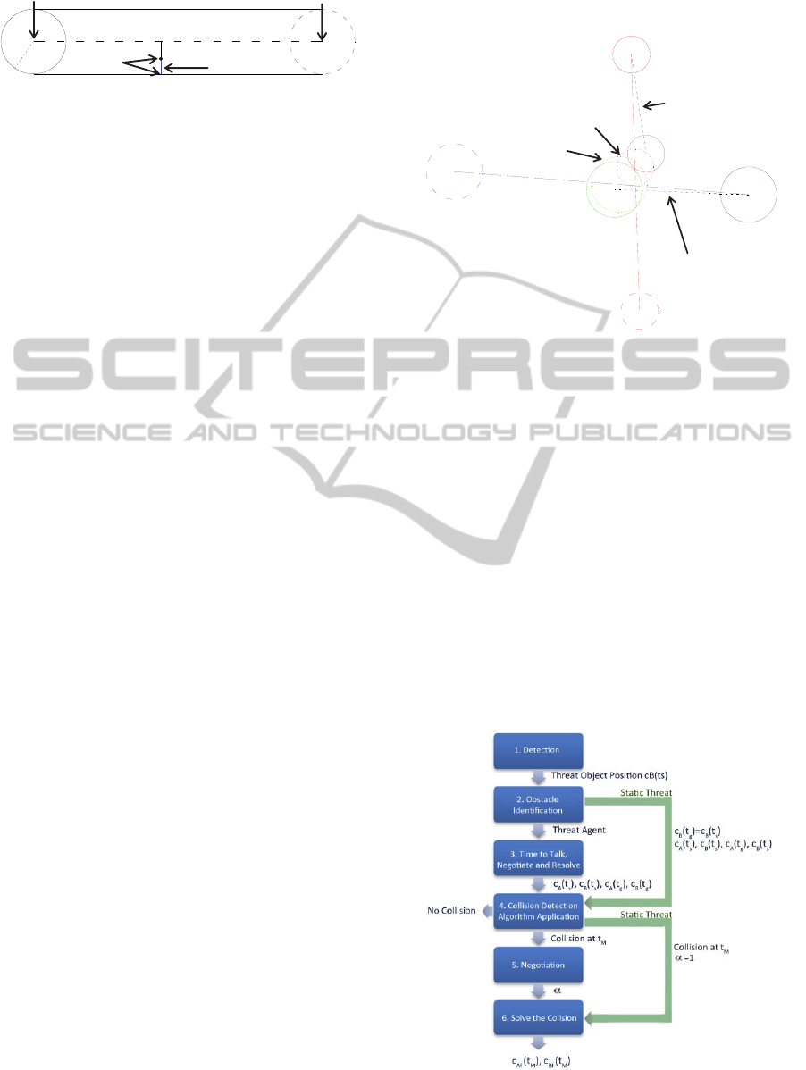
Figure 2: Finding the parameters
c
, d
M
, O
, and
MTD
v
ˆ
.
3.2 Determining Avoiding Collision
Configurations
Let two circles A and B be considered enveloping
two mobile robots or agents, and following the
straight-line trajectories previously shown.
Assuming that the previous distance-computation
technique returns the parameters:
c
[0,1], d
M
<0,
t
M
[t
s
,t
g
], and the unit vector
MTD
v
ˆ
, then a collision
between both mobile robots or agents has been
predicted. The A and B positions where they would
be at their maximum penetration d
M
, are respectively
A(t
M
) and B(t
M
) with
))()((λ)()(
:),()(
))()((λ)()(
:),()(
sBgBcsBMB
BMBM
sAgAcsAMA
AMAM
tctctctc
rtctB
tctctctc
rtctA
(9)
An avoiding-collision configuration (position and
time) for mobile circles A and B are generated by
simple translating A(t
M
) and B(t
M
). Let A
f
(t
M
) and
B
f
(t
M
) be the mention collision-free configurations,
ˆ
α)1(δ)()(
:),()(
ˆ
αδ)()(
:),()(
f
ff
f
ff
MTDMMBMB
BMBM
MTDMMAMA
AMAM
vdtctc
rtctB
vdtctc
rtctA
(10)
where c
A
(t
M
) and c
B
(t
M
) has been defined by (9).
Parameter 1 is a safety threshold. If =1, then
configurations c
Af
(t
M
) and c
Bf
(t
M
) will be in contact.
Finally, parameter
[0,1] configures the degree of
motion modification applied to each mobile robot or
agent. In this way, if =1, then c
B
(t
M
) and c
Bf
(t
M
) are
equal and, consequently, mobile robot or agent B do
not change its current motion. A graphical example
is shown in Figure 3.
The original A and B motions are divided in
order to avoid a predicted collision. Therefore, A’s
first submotion is defined from start position c
A
(t
s
) at
time t
s
to goal position c
Af
(t
M
) at time t
M
. Meanwhile,
A’s second submotion is defined from start position
c
Af
(t
M
) at time t
M
to goal position c
A
(t
g
) at time t
g
. B’s
motion is analogously divided.
Figure 3: Avoiding collision configurations with =0.7
and =1.03.
4 HYBRID CONTROL
COLLISION AVOIDANCE
The implementation of the collision avoidance
proposed methodology has six phases (see Figure 4).
A scenario where multiple robots follow a path
infinite straight line between two target points is
considered. These two points are alternated when
they are achieved. All robots have their
representation as a software agent in the MAS which
encompasses the whole system, so there is no
moving object within the scene that is not a software
agent.
Figure 4: Phases of the proposed methodology.
O
r
A
+r
B
c
A
(t
s
)c
B
(t
s
)
c
A
(t
g
)
c
B
(t
g
)
O
d
M
MTD
v
ˆ
c
A
(t
s
)
c
B
(t
s
)
c
A
(t
g
)
c
B
(t
g
)
c
A
(t
M
)
c
B
(t
M
)
c
Af
(t
M
)
c
Bf
(t
M
)
New motion for A
New motion for B
Multi-AgentSystemsforEvasiveManeuversofMobileRobotsthroughAgreements
143

Observing equation (1) is easy to conclude that
the maximum approach d
M
between in-motion
circles A and B will be obtained by finding the
parameter
c
[0,1] that minimizes
Phase 1: Detection. The local system (each
robot) has defined a detection object area. In the
first phase, the local system of the robot detects
an obstacle that may be a threat of collision at
some point (from now threat-object) and
calculates the position of threat-object in the
global scenario. This position is sent to the agent
who represents the local system in MAS to
manage the threat as is described below.
Phase 2: Obstacle Identification. When an agent
receives the position of a threat-object (from now
threat-position) by the local system, it must
identify what kind of threat it is: a moving object
or a static object. To know this, it adds a distance
(formula) to the threat-position to create a
circular area of position of threat-object. The
agent detects the threat (from now detector-
agent), consults the other agents to know who is
located within that area of threat. If there is not
any agent within that area, then the threat is
identified as a static object threat (static-threat)
and directly the Phase 4 is performed. Otherwise,
the threat-agent is identified through
communication among agents and the Phase 3
starts.
Phase 3: Time to Talk, Negotiate and Resolve.
When the two involved agents in a possible
threat have been identified, the communication
between them is used to obtain the information
needed to apply the detection algorithm
presented in 3.1. As already mentioned, the
inputs of the algorithm are four: the positions of
each of the agents involved in that instant (c
A
(t
s
),
c
B
(t
s
)) and the target positions where they will be
at time t
g
(c
A
(t
g
), c
B
(t
s
)). The problem is that this
time t
g
must be the same for the two robots and
each one may take a different time to reach the
assigned destination. Therefore, to calculate the
time t
g
, the agents communicate to each other to
know which one reaches its destination before.
The agent that plans to take more time to reach
their destination calculates an intermediate
destination from its current trajectory and the
arrived time of the other agent to its destination.
In this way the two agents shared the time it
takes to reach their destination and collision
detection algorithm can be implemented.
Phase 4: Collision Detection Algorithm
Application. As already mentioned, the input
requirements to implement collision detection
algorithm are: current position coordinates of
detector-agent (c
A
(t
s
)), its destination, (c
A
(t
g
)),
current position of threat-object (c
B
(t
s
)) and its
destination (c
B
(t
g
)). If in the Phase 2, the threat-
object was identified as a static-threat, the target
is the same as the initial position (c
B
(t
s
)= c
B
(t
g
)).
Therefore the inputs are applied to the algorithm
and it returns the probability of collision with the
threat-object. In case there is no collision, threat
is discarded and the method ends but if a
collision is detected, the method informs to
detector-agent the time of maximum penetration
(t
M
) to be produced.
The next step is to avoid the collision by the
method described in section 3.2. If the object is a
static-threat, the detector- agent should take over
the entire cost of the collision avoidance (=1)
and jump to Phase 6. Otherwise the negotiations
between the two agents involved are opened to
decide how much charge is allocated to each
Phase 5: Negotiation. To decide the load
percentage (
) that each robot will have in the
collision avoidance, the two agents communicate
with each other and exchange parameters such as
priority, the weight of the transported load, the
difficulty of manoeuvring, speed at which each
one moves, etc. In summary, they exchange a
number of parameters that define the easiness or
availability that each agent offers to change its
trajectory and avoid collision. Once each agent
agreed with the selection of
, the detector-agent
runs the last method described below.
Phase 6: Solve the Collision. The detector-agent,
by the method 3.2, computes the two new
positions that the robot should be achieve at time
t
M
to avoid collision. The threat-agent receives,
from the detector-agent, the avoidance position
(c
Bf
(t
M
)) and the time in which must be achieve.
Both change their trajectories to go to the new
destination partial (c
Af
(t
M
), c
Bf
(t
M
)) at the right
time. Once it’s reached, the collision is resolved,
each robot continues its original path and the
method ends.
In order to test the effectiveness of this method,
different scenarios with mobile robots has been
simulated. Figures 5 and 6 show the executions
obtained in two simulations. In the first one four
robots (circles green, blue, black and pink) are
considered. The robot initial positions are the
corners of the arena, and they must arrive to the
opposite corner (marked by a star). The figure also
shows the detection area (a trapezoid in front of each
ICINCO2013-10thInternationalConferenceonInformaticsinControl,AutomationandRobotics
144
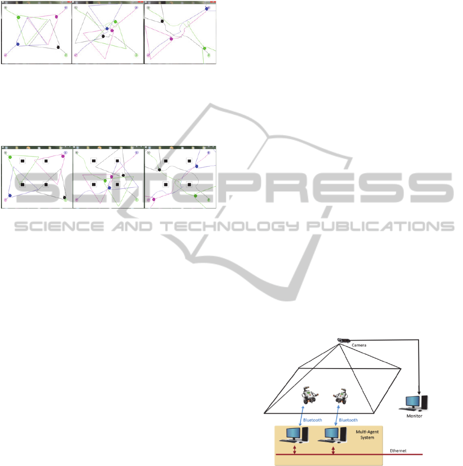
robot), and the final path described by the robot for
the first seconds of the simulation.
Figure 5: Simulation 1: Collision avoidance simulation
with four robots.
Figure 6 shows a similar situation but in this case
there are four static obstacles, marked with black
squares.
Figure 6: Simulation 2: Collision avoidance simulation
with four robots and static obstacles.
5 PRACTICAL
IMPLEMENTATION WITH
MOBILE ROBOTS
A practical implementation with mobile robots has
been developed in order to test the robustness of the
presented algorithm. The mobile robots used are
LEGO Mindstosrms NXT and the platform for the
management of MAS chosen was JADE.
The JADE platform is completely implemented
in JAVA. It supports coordination of multiple agents
according to FIPA specifications and provides a
standard implementation of agent communication
language FIPA-ACL.
JADE (http://jade.tilab.com) was originally
developed by Telecom Italia and is distributed as
free software being completely compatible with Java
Development Kit (JDK) 1.4 or higher, including the
functionality for basic agents, scheduling agents’
behavior, the implementation of FIPA ACL
specification for sending and receiving messages,
classes useful for programming FIPA protocols,
information management using ontologies, etc… In
addition, the platform also provides FIPA (AMS,
directory facilitator and MTS) to run on one or more
Java Virtual Machine (JVM) where each JVM is
seen as an environment where agents can execute
concurrently and exchange messages, organizing
containers.
On the other hand, LEGO Mindstorms NXT
(http://mindstorms.lego.com) was introduced by on
the International Consumer Electronics Show in
2006 and nowadays is often used in the research
community to prove theories and carry out practical
developments. The firmware of the robot chosen to
program this work has been LeJOS
(http://lejos.sourceforge.net) because it offers object-
oriented programming in JAVA.
For the practical experiment, two LEGO
differential wheeled mobile robots have been built
(Campion, Bastin, Dandrea-Novel, 1996). Each
robot has defined two destinations points. In order to
achieve the trajectory, a control strategy based on a
pure pursuit algorithm (Wallace, et. al., 1985) was
implemented in the robots. The LEGO robots have
been equipped with a ring of proximity sensors to
detect possible obstacles. Each ring has four SHARP
IR (www.sharpsma.com) proximity sensors as
peripherals of an I2C multi-master serial single-
ended computer bus. Those sensors provide a
detection range over forty centimeters.
Robots are connected to their software agents
(computers) via Bluetooth and those computers are
part of a network that forms the overall MAS
through JADE. The connection diagram is presented
in Figure 7. Each robot carries a triangle to detect its
position from an overhead camera located at the top
of the scenario. This camera is also used to
monitoring and minimizing odometry problems.
Figure 7: Control architecture for the practical
experiments.
These robots have multiple threads running
different functional modules. Each of them has one
module to control the robot trajectory, a second one
for detection that manages the IR sensors and a third
one for communication that receives and sends
information to the software agent (see Figure 8).
While IR sensors does not detect anything, the
robot follows its fixed trajectory, but when
Multi-AgentSystemsforEvasiveManeuversofMobileRobotsthroughAgreements
145
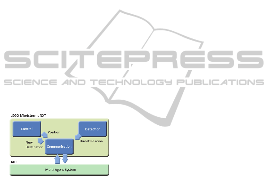
something is detected by IR, the communication
module informs to the software agent and expects a
solution to the possible collision from MAS. If the
solution leads to a new destination for the robot, the
communication module receives the new destination
and sends it to the control module for change the
path.
The management of the agents in JADE is
simple. When a software agent receives the position
of a detected threat, the agent asks everyone if
anyone is located in the threat area. Thus, if other
robot is the threat, it’s identified as the threat agent
and they exchange their destinations and speeds to
verify if there will be a collision or not. If finally
there is it, they negotiate the way to avoid it and
send the new destinations and speeds to their
respective robots.
In http://idecona.ai2.upv.es, a video
demonstration of practical experiment with Lego
robots (Robots Móviles folder, at videos multimedia
gallery) and two compiled versions of the platform
that allow the simulation with robots (Desarrollos de
Software folder, at Results option, Project menu) can
be obtained. The video shows how the robots try to
follow their trajectories but they have to change
them in order to avoid the collisions.
Figure 8: Modules connection scheme between the robot
and the MAS.
6 CONCLUSIONS
A collision avoidance method that takes advantages
and benefits of MAS has been presented in this
work. This method is located one level above the
traditional methods of obstacle avoidance where the
management is performed locally and the possible
communications between the local systems are
solved functionally. The application of techniques
provided by the area of artificial intelligence to the
robotic area opens a wide range of possibilities that
offers more natural results and gives human
characteristics of communication like negotiation
between robots.
This paper also introduces a degree of flexibility
and negotiation between two agents or robots by
means of a parameter, , in the collision avoidance
strategy. This parameter quantifies the percentage of
the original trajectory deviation of an agent while
avoiding a predicted collision. In a future work, this
percentage will be negotiated in accordance with an
optimization of the dynamics and kinematic
properties of the involved agents.
This work has succeeded in unifying concepts of
agent theory with concepts from the area of mobile
robotics, providing more intelligence to robots and
offering solutions that otherwise cannot be provided.
The methodology has been tested both in
simulations and in real executions with mobile
robots.
The kinematic configuration of the used agents is
holonomic, then considering only linear trajectories
might be acceptable. However, as a future work, the
collision detection using another kind of movements,
like natural Splines and Bezier curves are being
considered. In this way, collision detection involving
more than two agents are also being developed.
ACKNOWLEDGEMENTS
This work has been partially funded by the
Ministerio de Ciencia e Innovación (Spain) under
research projects DPI2010-20814-C02-02 and
DPI2011-28507-C02-01.
REFERENCES
Austin, J. L., 1962. How to Do Things With Words.
Oxford University Press: Oxford, England.
Bernabeu E. J., 2009. Fast generation of multiple
collision-free and linear trajectories in dynamic
environments. IEEE Trans. Robotics 25(4), pp. 967-
975.
Bernabeu E. J., Tornero J., Tomizuka M., 2001. Collision
prediction and avoidance amidst moving objects for
trajectory planning applications.
Proceedings of the
IEEE Int. Conf. Robot. Automat.
, pp. 3801-3806.
Bruce, K. B., Cardelli, L., Pierce, B. C., 1997. Comparing
Object Encodings. Theoretical Aspects of Computer
Software. Lecture Notes in Computer Science
, volume
1281. Springer-Verlag, Berlin Heidelberg New York,
pp. 415–438
Cameron S., Culley R. K., 1986. Determining the
minimum translational distance between two convex
polyhedra.
Proceeding of the IEEE Int. Conf. Robot.
Automat.
, pp. 591-596.
Cameron S., 1990. Collision detection by four-
ICINCO2013-10thInternationalConferenceonInformaticsinControl,AutomationandRobotics
146

dimensional intersection testing. IEEE Trans. Robot.
Automat.
, 6(3), pp. 291-302.
Campion, G., Bastin, G., Dandrea-Novel, B. 1996.
Structural properties and classification of kinematic
and dynamic models of wheeled mobile robots.
IEEE
Transactions on Robot. Automat.
, 12(1), pp. 47–62.
Choi Y-K., Wang W., Liu Y., Kim M-S., 2006.Continuous
collision detection for two moving elliptic disks. IEEE
Trans. Robotics,
22(2), pp. 213-224.
Fatima, S., Wooldridge, M., Jennings, N. R., 2001.
Optimal negotiation strategies for agents with
incomplete information.
Intelligent Agent series VIII:
Proceedings of the 8th International Workshop on
Agent Theories, Architectures, and Languages (ATAL-
2001)
of lecture Notes in Computer Science, volume
2333, pages 53-68. Springer Verlag, Berlin, Germany.
Huhns, M. N., Malhotra, A. K., (1999). Negotiating for
Goods and Services.
IEEE Internet Computing, 3(4),
pp. 97-99.
IDEMOV-IDECONA research project web page.
http://idecona.ai2.upv.es/
Iglesias C. A., Garijo M., Gonzales J. C., 1999. Survey of
Agent-Oriented Methodologies
. Intelligent Agents V:
Agents Theories, Architectures, and Languages
Lecture Notes in Computer Science,
volume 1555,
Springer-Verlag Berlin Heidelberg, pp. 317-330.
Java Agent Development Framework. http://jade.tilab.com
Lalish E., Morgansen K. A., 2008. Decentralized reactive
collision avoidance for multivehicle systems.
Proceedings of the
IEEE Int. Conf. on Decision and
Control
, pp 1218-1224.
LEGO home page. http://mindstorms.lego.com.
LeJOS: Java for LEGO Mindstorms.
http://lejos.sourceforge.net.
Michalewicz, Z., 1996. Genetic Algorithms + Data
Structures = Evolution Programs
. Springer-Verlag,
Berlin Heidelberg New York.
Rahwan, I., Sonenberg, L. Dignum, F., 2004. On interest-
based negotiation.
Advances in Agent Communication
Workshop, Lecture Notes in Artificial Intelligence
,
volume 2922, Springer-Verlag, Berlin, pp. 383-197.
Redon S., Kheddar A., Coquillart S. 2002. Fast continuous
collision detection between rigid bodies.
Computer
Graphic Forum
, 21(3), pp. 279-288.
Russell, S. J., Norvig, P., 2009.
Artificial Intelligence: A
modern approach
. Prentice Hall Series in Artificial
Intelligence, Upper Saddle River, New Jersey.
Schwarzer F., Saha M., Latombe J-C., 2005. Adaptive
dynamic collision checking for single and multiple
articulated robots in complex environments.
IEEE
Trans. Robotics,
21(3), pp. 338–353.
Searle, J., 1969. Speech acts:
An essay in the philosophy of
language
. Cambridge, England: Cambridge
University.
SHARP Optoelectonic device GP2y0A21YK.
www.sharpsma.com/webfm_send/1208
Singh, M. P., Huhns, M. N., 1999. Multiagent Systems for
Workflow
, International Journal of Intelligent
Systems in Accounting, Finance and Management
,
volume 8, John Wiley & Sons, Ltd., pp. 105-117.
Tang M., Kim Y. J., Manocha D., 2009. C2A: Controlled
conservative advancement for continuous collision
detection of polygonal models.
Proceedings of the
IEEE Int. Conf. Robot. Automat.
, pp. 849-854.
Urmson, C., Anhalt J., Bagnell D., Baker C., 2008.
Autonomous driving in urban environments: Boss and
the urban challenge.
Journal of Field Robotics, 25(8),
pp. 425-466.
Van den Berg J., Guy S. J., Lin M., Manocha D., 2011.
Reciprocal n-body collision avoidance.
Proceedings of
the 14th Int. Symp. on Robotics Research (ISRR),
Springer Tracts in Advanced Robotics, volume 70,
Springer-Verlag, pp. 3-19.
Van den Bergen G., 2005. Continuous collision detection
of general convex objects under translation. Game
Developers Conf. Morgan Kauffmann Publishers
.
http://www.dtecta.com/interesting.
Van Leeuwen, J. (ed.), 1995. Computer Science Today.
Recent Trends and Developments.
Lecture Notes in
Computer Science
, volume 1000. Springer-Verlag,
Berlin Heidelberg New York.
Wallace, R., Stentz A., Thorpe C., Moravec H., Whittaker
W., Kanade T. 1985. First Results in Robot Road-
Following. Proc. International Joint Conference on
Artificial Intelligence (IJCAI)
, pp.1089-1093.
Wooldridge, M., 2002.
An Introduction to MultiAgent
Systems
. John Wiley & Sons: Chicester, UK.
Multi-AgentSystemsforEvasiveManeuversofMobileRobotsthroughAgreements
147
