
Path Planning Optimization based on B
´
ezier Curves through Open-doors
Way Point
Simon Landrault, Philippe Lucidarme and Nicolas Delanoue
LISA, University of Angers, 62 avenue Notre Dame du Lac, 49000 Angers, France
Keywords:
Mobile Robots, Path-Planning, Vorono
¨
ı Diagrams, B
´
ezier Curves, Way Points.
Abstract:
Generalized Vorono
¨
ı Diagrams has been demonstrated to be a relevant tool for planification in a mobile
robotics context. Therefore, the generated trajectories may suffer of discontinuities and non-optimality. This
paper introduces a reflexion on the use of B
´
ezier curves to solve both of these drawbacks. The key idea of this
paper is to be able to smoothen a trajectory in order to save traveling time and therefore reduce displacement
and overall consumption (in our mobile robotics context: reduction of battery usage and localization errors).
The presented work is firstly detailed and explained on a synthetic map, and experimental results with mobile
robots are presented. Disadvantages and advantages are discussed at the end of the paper.
1 INTRODUCTION
Path planning is a key task in many fields, especially
in mobile robotics. It started in the early 60’ with the
first industrial robot. Nowadays, we can find those ap-
plications everywhere, from the industrial application
with the robotic arms assembling cars, to the personal
house cleaning ”Roomba” robot. However, the solu-
tions are different, the movement is not developed in
the same way. The first one is developed under the
supervision of a human operator, to guarantee a cor-
rect accuracy and be sure of the repeatability of the
placement in a defined universe. In the second case,
the trajectory is studied ”on-line” and completely au-
tonomously. The robot will move in the space and de-
sign a map of the environment to determine the path
to follow (Jagannathan et al., 1994) and (Dierks and
Jagannathan, 2009).
In our context, we had to develop a robot able to
discover and create a map of it on-line. Therefore, it
needed to plan the trajectory and move around effi-
ciently simultaneously. It is in these conditions that
this solution as been submitted as a research work.
The aim of the present work is to improve the cur-
rent planification and to be able to have an efficient
and smooth trajectory. Those two characteristics are
important for different reasons. The first is, of course,
the traveling time. The more direct is the trajectory
and the more time is saved. This result has conse-
quences on other levels. For example, the less the
robot travels and the less energy will be consumed
Figure 1: Map used for the demonstration.
and the fastest it travels the more time remains to in-
crease the exploration.
This paper will now introduce the different opti-
mization and algorithms used to develop the trajec-
tory. Some algorithms are already known. They will
be explained here as a state of the art and why they
are useful in our application.
Note that the demonstration will be supported by
examples applied on a synthetic map. In order to
have comparable results, the same map will be kept
all along and can be seen on the Figure 1.
Let us assume the map is discretized and stored in
156
Landrault S., Lucidarme P. and Delanoue N..
Path Planning Optimization based on Bézier Curves through Open-doors Way Point.
DOI: 10.5220/0004431301560161
In Proceedings of the 10th International Conference on Informatics in Control, Automation and Robotics (ICINCO-2013), pages 156-161
ISBN: 978-989-8565-71-6
Copyright
c
2013 SCITEPRESS (Science and Technology Publications, Lda.)
the computer’s memory as a grid of cells. Each cell
represent an information about the space (typ. obsta-
cle or not). For this study, we will store a Boolean in
each cell meaning the presence of an obstacle (true)
or not (false).
Working straight from the discretized map gener-
ates the first problem : the space size for the research
of the best path. In two dimensions, we will have a
n × m cells. If both dimensions grow by 2, the size
of the research space is then multiplied by four. The
growth is exponential with the dimension.
Another problem with this representation is the
accuracy. A fine representation of the environment
and path needs a high sample rate that increases the
size of the overall grid, memory consumption and
computing time.
A last issue with this representation is the graph of
the connection between each node (generally equiva-
lent to cells). The bigger the space and the bigger
will be the number of connection to pile up in mem-
ory. For a 2 dimensional space, there are different
kinds of connectivity to define links between cells:
4-connectivity (only horizontal and vertical moves)
and 8 connectivity (same as before, moreover diago-
nal moves are allowed). In a mobile robotics context,
none of them, combined with classical approaches
(Dijkstra or A* based algorithms) provides a satisfy-
ing trajectory.
Some other techniques like rrt (LaValle,
2006)(rapidly random explored trees) has also
been proposed in the state of the art. Even if these
techniques has been proven to be very fast and quite
efficient in practice, some drawbacks still remain.
Such algorithms provides non-optimal solutions
without any guaranty of convergence. As these
techniques are based on a random exploration of
the environment, the repeatability is very poor. For
these reasons, our work is mainly focused on a
Vorono
¨
ı Diagram based approach that seems to be an
interesting avenue for research.
Previous works have shown that the use of Gen-
eralized Vorono
¨
ı Diagrams (Fortune, 1987) (Seda and
Pich, 2008) is a big step forward to tackle those prob-
lems. Such diagrams are used to quickly explore the
space and thus reduce it to a graph where nodes are
particular cells. Indeed, each cell of the graph repre-
sents a point which is equidistant to any change in the
space (in our case, a change will be represented by the
configuration of each cell: navigable or not).
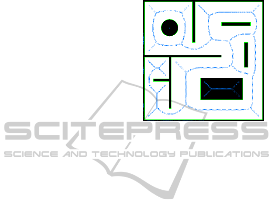
Applying this representation to a standard map
will result in the obtention of a graph with nodes, con-
nected to each other. Nodes are only placed in the
middle of the free space between walls. Such com-
puted diagram is shown on Figure 2.
Figure 2: Vorono
¨
ı graph on a map (the blue circles are the
Vorono
¨
ı cells).
There is still one limit which remains similar to
the one before: the granularity of the space. The
finer the graph will be and bigger memory space will
be used. However, this amount will always be very
smaller than the initial grid representation. Note also
that the computation of the Vorono
¨
ı Diagram has been
proven to have a linear complexity (Fortune, 1987).
2 TRAJECTORY PLANNING
To simplify our presentation, we will consider that the
graph is connected, from one point we can always
reach another one. The input of our path optimiza-
tion algorithm can be obtained by any path planning
algorithms (A*, Dijkstra algorithm, . . . ). On Figure 3,
the path from the top left node of the Vorono
¨
ı graph
to the bottom right was computed using the Dijkstra’s
algorithm.
2.1 Optimization Issue
As seen on the Figure 3, different spots can be op-
timized. For example, the orange circled area is not
optimal. Indeed, to be more efficient, the trajectory
would have to go less high and more straight. In this
way the robot would save energy (less turn and accel-
eration) and use less time to travel.
PathPlanningOptimizationbasedonBézierCurvesthroughOpen-doorsWayPoint
157
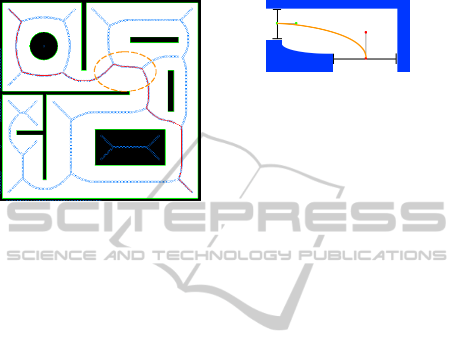
Figure 3: Vorono
¨
ı trajectory with a possible optimization
area.
3 B
´
EZIER CURVE BASED
TRAJECTORY OPTIMIZATION
3.1 B
´
ezier Curve
In order to solve the problem described in the previous
section, the trajectory need to be smoothed. To do
so, the application of a polynomial B
´
ezier (Demengel
and Pouget, 1998) curve can be used. In a simple way,
this curve will use each node from the Vorono
¨
ı graph
which are visited by the path finding algorithm to be
computed. A node will then be considered as a ”way-
point” of the B
´
ezier curve. To draw this curve, each
way-point is pondered by a polynomial coefficient at
a time t. The definition function of this curve will
be:
∑
n
i=0
B
n
i
(t).P
i
with t ∈ [0, 1], B
n
i
are the Bernstein
coefficient and P
i
are the way-points.
The problem with this approach is that the number
of way-point will decrease the smoothing effect of the
curve. In order to counter that, another approach is
followed, using less points and a ”part-to-part” defi-
nition of the curve.
3.2 Gate Way-point
To avoid the lost of the smoothing effect of the B
´
ezier
curve by using too many way-point, a new method
of way-point definition is here proposed. This algo-
rithm is based on the human behavior when going
trough a door. The main idea is that whenever we (hu-
mans) want to go through a door, we will do it with
our shoulder oriented in the perpendicular axis of the
door, and the body centered in the doorway.
Figure 4: B
´
ezier curve (in orange) through doors (green and
red dots are B
´
ezier way-point for each door and blue area
are walls).
Another observation point is that in a space, a door
represent a local minimum in the function defining the
trajectory. Therefore, it is rather easy to detect them.
From this statement, it is decided that the center
of all the ”doors” will be a way-point for the B
´
ezier
curve. To be able to compute a B
´
ezier curve, at least 4
points are needed. From one door to another it makes
only two. Two others will be added upon the direction
and the size of the door. Two way point are defined in
the following way:
• the way-point is placed on a virtual line perpen-
dicular to the axis of the door,
• the wider is the door and the furthest from its cen-
ter can be the way-point.
From this stage, four way-point are defined. The
B
´
ezier curve can be defined using the following ex-
pression:
P(t) = P
0
(1−t)
3
+3P
1
t(1−t)
2
+3P
2
t
2
(1−t)+P
3
t
3
for 0 ≤ t ≤ 1 as seen on Figure 4.
To define a complete path, we just need to define a
trajectory from door to door and then merge all those
path together to obtain the complete navigation. A big
advantage of this method is that the navigation will
always be safe when going through critical places (the
doors, local minimum), as seen on Figure 5. However,
the method is not yet proved to be safe (obstacle-free)
in between. The next part will demonstrate why and
what solutions/tests could be experimented.
3.3 Drawback, Limitation
and Discussion
3.3.1 Size of the Door
As seen on the Figure 5, one of the first limit of this
B
´
ezier smoothing is that the doors are not limited in
width. It means that even in a big space there is going
to be a door to start it and so a way-point for the curve.
The result is that the curve as to make some rather big
detour and so make a lost of time for the robot.
One way to sort out this limit is to use a threshold
on the size of a door. If it’s bigger than this thresh-
old, it is not taken in account to create a way-point.
ICINCO2013-10thInternationalConferenceonInformaticsinControl,AutomationandRobotics
158
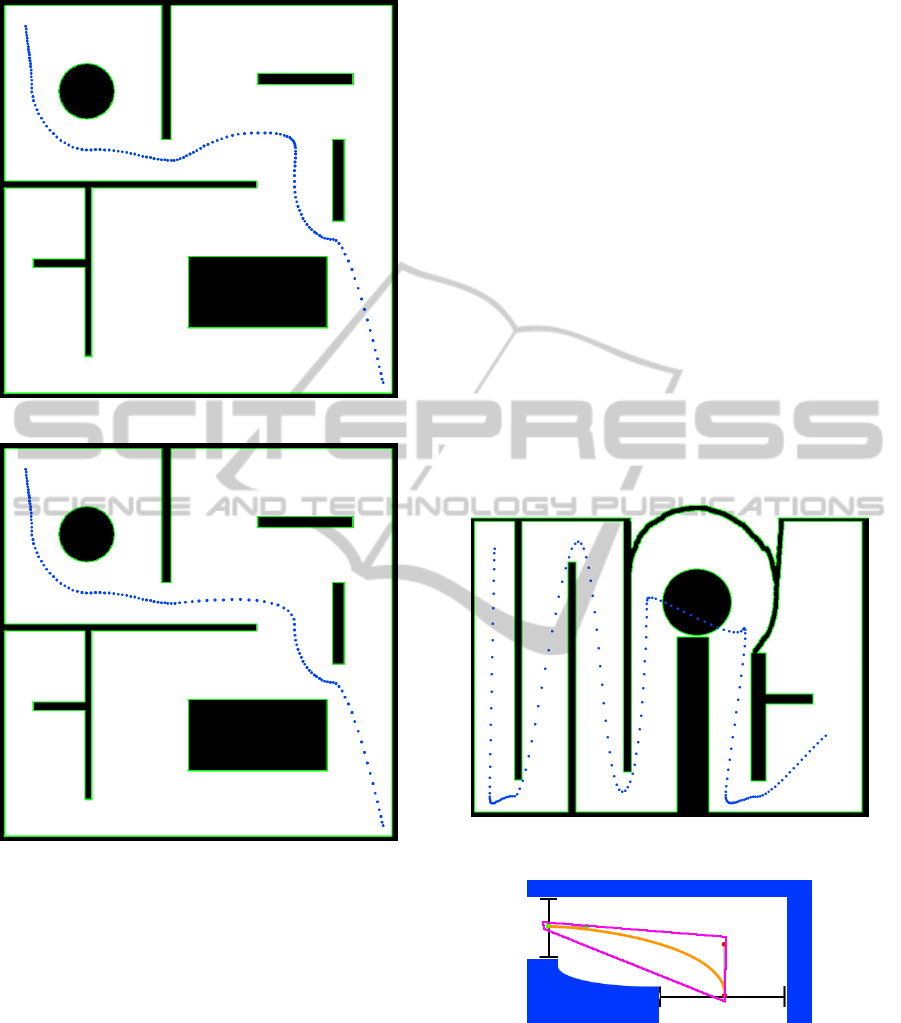
Figure 5: B
´
ezier curve (in blue) through doors.
Figure 6: B
´
ezier curve (in blue) through doors, with a limit
on the ”door width”.
However, this solution depends on the context (size
of the corridor, scale of the map...) and is difficult to
be determined in an autonomous way of decision. A
manual thresholding could give the result seen on the
Figure 6 as opposite to the Figure 5 without it.
3.3.2 Safety of Traveling
As for now, the question of safety of traveling cannot
be answered (as stated in the introduction, it is still
a work in progress). The study is now at this point
of solving the answer of the question: “Is it always
collision-free ?”. In most of the case, the empiric
results show that the computed smooth trajectory is
safe. However, in some particular case (with aligned
circular wall) the path will go through the wall (See
figure 7).
As a perspective of this work, two solutions have
been emitted. First, a property of the B
´
ezier curve
says that the curve is always contained in the convex
hull that defined it (See figure 8). This mean that we
could check if the convex hull intersects a wall or not.
If yes, then the trajectory between those two doors
need to be improved. If no, then this part of the curve
is collision-free.
Another idea is to check if the circumscribing cir-
cle of the envelope is within a corridor defined by the
Vorono
¨
ı graph. The notion of the corridor is given by
the union of all circular spaces between a Vorono
¨
ı site
and the obstacles it refers to (as seen on the Figure 9).
In this circle, no obstacles can be found. Therefore,
testing if the circumscribing circle of the envelope is
in the corridor allows to conclude on the safeness of
the path. The advantage of this solution is the speed
of the computation; it is quite fast to check if a circle
is included in an union of other circles.
Figure 7: Non-obstacle-free trajectory.
Figure 8: Envelope (pink) of a B
´
ezier curve (orange).
4 EXPERIMENTS
This work takes place in a larger project called Cart-
O-matic. Our team was involved in a robotics compe-
tition (D
´
efi-CAROTTE) founded by the French Re-
search Agency (ANR) and the General Delegation
for Armaments (DGA). The aim of this contest was
PathPlanningOptimizationbasedonBézierCurvesthroughOpen-doorsWayPoint
159
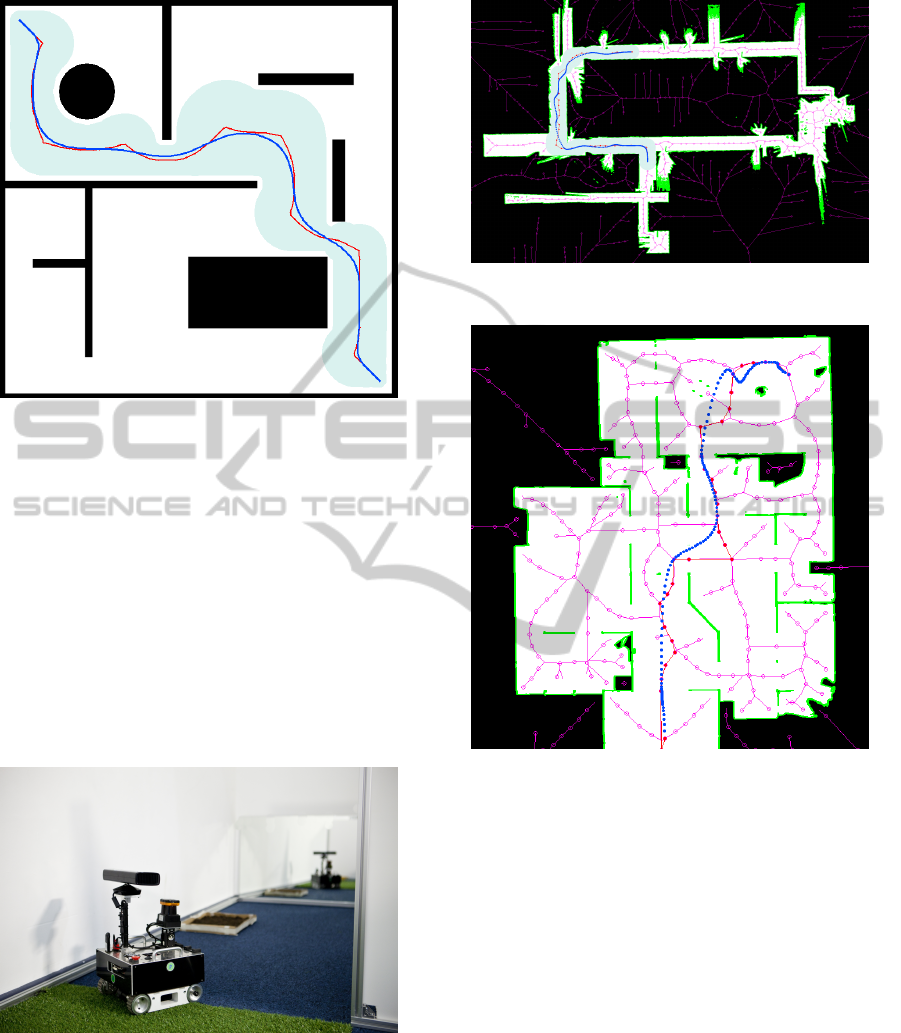
Figure 9: The corridor (Grey) for a path (blue).
to map and locate objects in a structured environ-
ment similar to an apartment. The particularity of
our team was the use of a multi-robot strategy (Shah-
bandi and Lucidarme, 2012) (Bautin et al., 2011). Our
team designed and built seven identical mobile robots
called MiniRex (MINIature Robot for Exploration) il-
lustrated in Fig. 10 . Each robot is composed of an
Embedded PC (proc. Atom 1.6GHz), inclinometer,
ultrasonic sensors for navigation, LIDAR for localiza-
tion and mapping, and an RGB-D sensor (Microsoft
Kinect) for object recognition. Figures 11 and 12 il-
lustrate the proposed algorithm applied on environ-
ments mapped by robots.
Figure 10: The MiniRex robot while exploring its environ-
ment.
5 CONCLUSIONS
As seen in the development, this optimization method
introduces advantages on the path planification prob-
lems. The global idea of reducing the best trajectory
seems to be reached and the ”human-based” behavior
Figure 11: Illustration of a trajectory inside a mapped build-
ing from the university of Angers.
Figure 12: Illustration of a trajectory in a multi-robot
mapped bulding.
tends to give a reliable solution and elegant way of
displacement.
However, even if in most cases the algorithm
seems to work, the lack of a mathematical proof can-
not allow to conclude on the efficiency of the method.
Moreover, as seen on Figure 7, some cases brings a
set of new problem to which solutions are not found
yet.
ACKNOWLEDGMENTS
This work has been partially supported by the French
National Research Agency (ANR) and General Del-
egation for Armaments (DGA) through the Cart-O-
matic project in the CAROTTE challenge.
ICINCO2013-10thInternationalConferenceonInformaticsinControl,AutomationandRobotics
160

REFERENCES
S. Jagannathan, S. Q. Zhu and F. L. Lewis Path planning
and control of a mobile base with nonholonomic con-
straints., Robotica, 1994, Volume 12, Issue 06.
T. Dierks and S. Jagannathan Neural Network Control
of Mobile Robot Formations Using RISE Feedback.,
IEEE Transactions on Systems, Man, and Cybernet-
ics, Part B: Cybernetics, Volume:39 , Issue: 2, April
2009.
M. Seda, V. Pich, Robot motion planning using generalised
voronoi diagrams, ISCGAV’08 Proceedings of the 8th
conference on Signal processing, computational ge-
ometry and artificial vision pp.215-220, 2008.
S. Fortune, A Sweepline Algorithm for Vorono
¨
ı Diagrams,
Algorithmica, vol. 2, pp. 153-174, 1987.
Thomas H. Cormen, Charles E. Leiserson, Ronald L. Rivest
et Clifford Stein, Introduction to Algorithms, MIT
Press et McGraw-Hill section 24.3, pp.595-601, 2001.
P. E. Hart, A Formal Basis for the Heuristic Determination
of Minimum Cost Paths, in IEEE Transactions on Sys-
tems Science and Cybernetics SSC4, vol. 4, no 2, pp.
100-107, 1968.
G. Demengel, J. P. Pouget, Mod
`
eles de B
´
ezier, des B-splines
et des NURBS - Math
´
ematiques des courbes et des
surfaces, ed.Ellipses ISBN: 9782729898069, 1998.
S. M. LaValle, Planning Algorithms,Cambridge University
Press, Cambridge, U.K., 2006.
A. Bautin, O. Simonin and F. Charpillet, Towards a commu-
nication free coordination for multi-robot exploration,
CAR 2011, 6th National Conference Control Archi-
tecture of Robots, May 2011, Grenoble, France.
S. G. Shahbandi and P. Lucidarme Object Recognition
Based on Radial Basis Function Neural Networks:
experiments with RGB-D camera embedded on mo-
bile robots., 1st International Conference on Systems
and Computer Science (ICSCS 2012), IEEE, Lille,
France, August 2012.
PathPlanningOptimizationbasedonBézierCurvesthroughOpen-doorsWayPoint
161
