
Creating Domain-Specific Modeling Languages with OPM/D
A Meta-modeling Approach
Arieh Bibliowicz and Dov Dori
Technion, Israel Institute of Technology, Haifa, Israel
Keywords:
Domain-specific Modeling Languages, Object-process Methodology, Meta-modeling.
Abstract:
Domain-specific languages and model-driven development are two promising approaches for tackling the
complexity of software systems development. However, creating domain-specific modeling languages is a
complex and lengthy task which makes the creation of DSMLs only feasible in large and complex projects. To
alleviate this difficulty, we developed OPM/D, a visual meta-modeling language for the definition of domain-
specific modeling languages. Languages in OPM/D are defined via a static structural meta-model of the
language and a set of validation rules that define the non-structural constraints of the language. The language
editor is created on-the-fly through interpretation of the static structure and validation rules, minimizing the
time between language definition and its use. Our approach has been applied to define a subset of the OPM
modeling language, and a prototype tools is being developed using the Eclipse platform and technologies.
1 INTRODUCTION
Developing and evolving complex software systems
is difficult. A large portion of software-intensive
projects get behind schedule, many of the features
they provide do not correspond to the ones the user
had required, they are not stable after delivery, and
their total costs are well above their initial estimated
ones. Several publications ((United States Govern-
ment Accountability Office, 2008), (White et al.,
2007) and (The Standish Group International, 2009))
show recent examples of these ailments. In the clas-
sical software engineering essay ”No Silver Bullet”
(Brooks, 1987), Fred Brooks noted two kinds of com-
plexity in software: essential and accidental. Since
”essential” complexity cannot be removed from soft-
ware, we must try to reduce the ”accidental” complex-
ity in the development of software systems. Two ad-
vances in software development propose ways to cope
with this ”accidental” complexity: Model Driven De-
velopment (MDD) and Domain-specific Languages
(DSLs). To join these two fields together, there is
need to create Domain-specific Modeling Languages
(DSMLs).
Developing DSLs is not a simple task, and it be-
comes even more complex when developing DSMLs.
To help reduce this complexity barrier, we have cre-
ated and implemented OPM/D, a simple yet powerful
modeling language for defining domain-specific mod-
eling languages. OPM/D is the first step in our goal of
creating fully executable DSMLs in a visual and intu-
itive way. This work is structured a follows: Section
2 surveys related work on the subject of DSML cre-
ation tools. Section 3 describes our approach for cre-
ating new DSMLs through OPM/D using a simplified
version of OPM as the language being defined, and
Section 4 discusses the approach and presents ideas
and plans for future development.
2 RELATED WORK
There are three basic approaches for developing
DSMLs: class frameworks, code generation toolkits
and meta-tool platforms.
Class frameworks (software development com-
ponents) provide the lowest level of abstraction to
the language creator, but allow a very high level of
customization. Developing languages using these
frameworks requires experienced software develop-
ers and long development times. Languages cre-
ated with these frameworks cannot be defined di-
rectly by domain experts (since most of them are
not software developers), neither do they allow lan-
guage prototyping because of their long development
cycles. Some examples of existing graphical class
frameworks are GEF (Eclipse Foundation, 2012a),
Netbeans Visual Library (Netbeans, 2010), JGraphX
473
Bibliowicz A. and Dori D..
Creating Domain-Specific Modeling Languages with OPM/D - A Meta-modeling Approach.
DOI: 10.5220/0004431704730479
In Proceedings of the 8th International Joint Conference on Software Technologies (ICSOFT-PT-2013), pages 473-479
ISBN: 978-989-8565-68-6
Copyright
c
2013 SCITEPRESS (Science and Technology Publications, Lda.)

(JGraph Ltd., 2013), Graphiti (Eclipse Foundation,
2012c), and JUNG (JUNG Framework Development
Team, 2010).
Code generation toolkits provide a higher level of
abstraction to the language creator. In these toolk-
its, the language editor is created by generating code
based on some type of language specification. While
these tools allow for both faster and easier definition
of DSMLs, customizing the code generated by these
tools is usually a complex task. Furthermore, changes
made to the generated code complicate changing the
original language specification and re-generating the
editor code. Some examples of generation toolkits are
GMF (Eclipse Foundation, 2012b), Visual Studio Vi-
sualization and Modeling SDK (Microsoft Corpora-
tion, 2012) and VisualDiaGen (Minas, 2004).
Meta-tool platforms provide a higher level or
flexibility by using meta-model language interpreta-
tion instead of code generation. In these platforms,
the language creator defines the meta-model of the
language using the definitions available in the tool.
When the user wants to create a model for a desired
language, the platform interprets the meta-model and
creates a matching editor for the model. Meta-tool
platforms support better meta-model evolution and in
some cases are able to validate meta-model changes
that may invalidate existing models. Some exam-
ples of meta-tool platforms are MetaEdit+ (MetaCase,
2013), GME (Davis, 2003), and Marama (Grundy
et al., 2013). Version 2 of the UML language (OMG,
2010) provides a mechanism that can be used to de-
scribe DSMLs using the profiles mechanism (Selic,
2007), but the authors are unaware of any systems
that implement the definition of a new DSML using
this mechanism.
OPM/D uses the meta-tool platform approach.
The main differences between OPM/D and existing
meta-tool approaches is that with OPM/D the en-
tire language definition is done visually. This is
in contrast with MetaEdit+, where the language is
defined using dialogs; GME, where language con-
straints are defined using OCL (OMG, 2012); and
Marama, which also uses OCL to define constraints.
3 CREATING DSMLS WITH
OPM/D
OPM/D provides a visual language and a methodol-
ogy to define domain-specific modeling languages.
New DSMLs are defined by creating a language meta-
model, which specifies the syntax of the language be-
ing defined and what operations the modeler can ap-
ply at each point during the model construction pro-
cess. This language meta-model is created using the
OPM/D meta-modeling language, which is a subset
of the graphical language used by the Object-Process
Methodology (OPM) (Dori, 1999). We decided to
use OPM as the basis our meta-modeling language
because of the following reasons:
1. OPM has been used to model real-world prob-
lems from different domains such as biological
systems (Dori and Choder, 2007) (Somekh et al.,
2012), ERP (Soffer, 2003) and Web Applications
(Reinhartz-Berger et al., 2002). This variability in
application domains provides a high level of con-
fidence that the language is rich enough to model
complex systems in general, and DSMLs in par-
ticular.
2. OPM allows for the modeling of both static and
dynamic aspects of a system. When defining a
DSML, both of these traits need to be defined:
static models define the static syntax of the lan-
guage, while dynamic models are used to validate
model changes at run-time.
3. Empirical experiments (Reinhartz-Berger and
Dori, 2005) suggest that OPM is easier to under-
stand than UML when modeling dynamic aspects
of a system, and at least as good as UML when
modeling structural aspects of a system.
An OPM/D language meta-model is composed of
two parts: (1) the static structure of the entities in the
language, and (2) a set of construction rules that vali-
date model construction operations done by the mod-
eler.
3.1 The OPM/D Meta-modeling
Language
An OPM/D language meta-model consist of a static
structure and a set of validation rules, both of which
are defined using Object-Process Diagram (OPD). An
OPD is a directed typed graph (Bibliowicz and Dori,
2011). The nodes of the graph can be Object nodes,
Process nodes, and State nodes, which must be con-
tained inside Object nodes. The links of the graph can
be Structural links and Procedural Links. Structural
links can be Aggregation, Exhibition or Specializa-
tion links. Procedural links can be Instrument, Con-
sumption and Result. The visual representation of the
OPM/D nodes and links is shown in Figures 1 and 2.
The essential semantics of OPM/D nodes and
links are described as follows (Due to lack of space,
it is impossible to formally define them here; a com-
plete and expanded definition of them can be found in
(Dori, 1999)):
ICSOFT2013-8thInternationalJointConferenceonSoftwareTechnologies
474
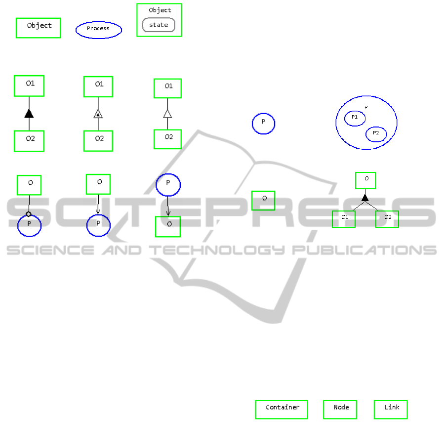
(a) Object (b) Process (c) State
Figure 1: OPM/D nodes.
(a) Aggregation
(b) Exhibition
(c) Specialization
(d) Instrument
(e) Consumption
(f) Result
Figure 2: OPM/D links.
• Object nodes define both data structures and vari-
ables. An object that contains a simple name (i.e.
Container) defines a new type named container
and an anonymous (not named) variable of that
type. An object that contains a name followed by
a colon and then another name (i.e. s : Source)
defines a new variable which named s of type
Source.
• Processes affect objects by consuming, creating or
affecting them.
• State nodes show possible states/values of the
containing object.
• Aggregation links define whole-part relations: the
whole is the source of the link, and the target is a
part of the whole.
• Exhibition links define properties: the target of
the link is a property exhibited by the source of
the link.
• Specialization links are similar to OO inheritance
relations: the target of the relation receives all the
parts and attributes from its parent, and can also
be used in place of its parent type.
• Instrument links denote that the target process
uses the source object, but it doesn’t change it.
• Consumption links show that the process con-
sumes the object, so it may not be used by other
processes occurring later.
• Result links show that a process yields an object.
Following the rules of OPM, nodes in OPM/D can
be in-zoomed or unfolded. In-zooming is used to
show the internal components that compose the node
(mostly used to describe process execution), while
out-zooming is used to show structural decomposition
of the node by placing it at the top of the diagram.
Both operations are shown in Figure 3.
(a) Process
(b) In-Zoomed Process
(c) Object
(d) Un-Folded Object
Figure 3: In-Zooming and UnFolding.
Having defined the basic syntax and semantics of
the OPM/D language, we can now describe how it is
used to graphically define DSMLs. We will do this by
using an example language that is a simplified version
of OPM.
3.2 Defining the Static Structure
Every OPM/D language starts with a basic meta-
model that contains the structure shown in Figure 4.
Figure 4: Initial language structure.
Two basic entities must be defined to create a lan-
guage: the container where language diagrams are
stored, and at least one node that can be added to this
container. In OPM/D, these definitions are done by
unfolding the container and node object.
In OPM/D, the static structure of a DSML is de-
fined via a meta-model that extends three primitive
objects: Container, Node and Link. These three nodes
are abstract nodes that are used as the basis for its
definition, and they cannot be instantiated in the new
language.
The following conventions define how the meta-
model is built. We will use the name ”element” for
the graphical nodes that appear in the new language:
1. All elements must inherit from the Node object.
CreatingDomain-SpecificModelingLanguageswithOPM/D-AMeta-modelingApproach
475
2. If an element can contain other elements, it must
also inherit from the Container object.
3. Non-leaf objects are abstract elements, and cannot
be drawn. Only leaf object elements can be added
to a diagram.
4. There must be at least one object which inher-
its from Container and not from Node. This el-
ement becomes the canvas in which the diagram
is drawn. More than one canvas may be defined
in the meta-model to provide model kinds for the
same language.
5. The Link hierarchy only defines the static hier-
archy of the link without defining how and two
which nodes the link may be connected. This is
done using validation rules, which are described
below.
Based on the above definitions, to start our exam-
ple, we need to define three types of elements: Ob-
ject, Process, and Link. This is done by unfolding the
Node object into a new diagram, as shown in Figure
5. We have added here an abstract node Thing, which
cannot be drawn on the diagram, but will be used later
on in the validation rules.
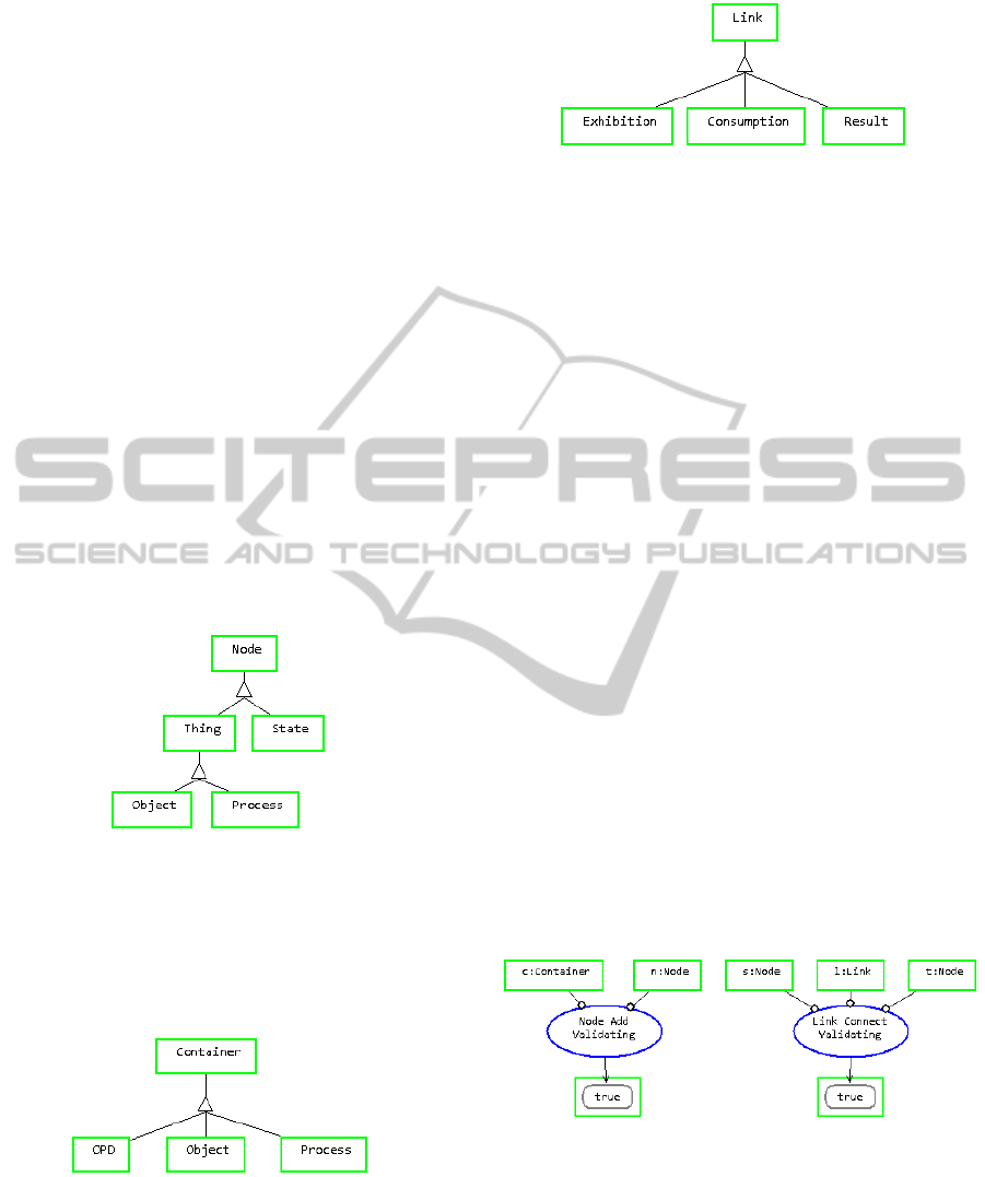
Figure 5: Unfolded Node object.
Having defined the nodes, we define the contain-
ers: OPD, Object, and Process. Notice that OPD is
not defined as a Node, therefore it is interpreted as
a canvas for the language. The definition is done by
unfolding the Container object as shown in Figure 6.
Figure 6: Unfolded Container object.
Finally, we define the links that may occur in the
language: Exhibition, Consumption and Result. The
unfolded Link object is shown in Figure 7.
The language defined above creates a new DSML
with one canvas (OPD), three nodes types (Object,
Process, and State), of which two are also containers
Figure 7: Unfolded Links object.
(Object and Process), and three links type (Exhibi-
tion, Consumption, and Result). We have not defined
validation rules or visual properties yet, therefore all
nodes in the language are drawn as rectangles, links
can connect between any two types of nodes, and con-
tainers can contain any type of nodes.
3.3 Validation Rules
Validation rules are applied when the user adds new
elements (nodes or links) to the diagram. We cur-
rently support only simple validation rules based on
the local context of the diagram. We plan to support
complex validation rules that can query the model to
verify the validity of an operation and validation rules
for other modeling operations, such as deleting ele-
ments. The built-in validation rules are:
1. Node Add Validating: validates whether a node
can be added to a container.
2. Link Connect Validating: validates whether a link
can connect two nodes.
These validation rules are shown in Figure 8. Here
we introduce a new type of notation in the object:
name : type. This notation indicates that the object
instance (data) is named name and that it if of type
is type, where type is one of the types defined in the
static structure of the language or one of the built in
types of OPM/D.
Figure 8: Initial validation rules.
To add new validation rules, we unfold the built-in
validation rules and change their parameter types and
the result of the validation. Continuing our example,
note the following:
1. A state can only be contained inside an object, as
shown in Figure 9. Notice that we first invalidate
the containment for all other containers, and then
validate only for object containers.
ICSOFT2013-8thInternationalJointConferenceonSoftwareTechnologies
476
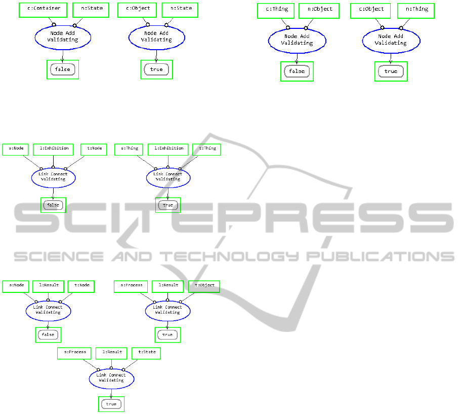
Figure 9: Validation of state containment.
2. Exhibition links can only start or end at things, as
shown in Figure 10.
Figure 10: Validation of exhibition link connection.
3. Result links must start at a process and end at an
object or state, as shown in Figure 11.
Figure 11: Validation of result link connection.
As seen in the examples, validation rules are
matched using the operation type and the types of the
parameters for which the validation rules are called.
For instance, the rule shown on the right-hand side
of Figure 9 is applied when a new node of type State
is added on top of an Object container, making the
operation valid. If another type of container were to
be selected, the rule on the left hand side of Figure 9
would be applied, invalidating the operation.
Not all operations must have a validation rule, in
which case the framework must decide what to do.
This decision is made by searching for the validation
rule that most closely matches the parameters pro-
vided by the applied operation. This may be prob-
lematic because there may be more than one match-
ing rule and it is possible to create contradictory rules.
Take for example the rules defined in Figure 12.
Figure 12: Contradictory validation rules.
If an Object node is added to another Object node,
should the operation be valid or invalid? Both options
can be possible matches. To break this inconsistency,
we determined that invalid rules take precedence over
valid rules. That is, if there is more than one matching
validation rule for an operation, all of the matching
rules must be valid for the operation to be valid.
3.4 Adding Visual and Non-visual
Properties
Visual representation is one of the key features of
DSMLs. Differentiating nodes by their visual prop-
erties makes models easier and faster to understand
(Moody, 2009). Furthermore, a node may have other
properties that are not represented visually but are part
of the information that the node contains. OPM/D
supports this by allowing the definition of visual and
non-visual properties for all meta-model elements.
Each element in the OPM/D meta-model can be
un-folded to define the visual and non-visual proper-
ties that it exhibits. Visual properties affect the visual
representation of the nodes, while non-visual prop-
erties add information which has no visual represen-
tation. We currently allow for the definition of one
visual property: Figure. Since OPM/D is developed
using Eclipse GEF/draw2d, a figure is an implemen-
tation of a draw2d Figure interface. Some built-in
draw2d figures are Rectangle, Ellipse, Polygon, and
Polyline. For non-visual properties, it is possible to
define any number of properties, where each property
must be of one of the basic Java primitive types (int,
boolean, String, etc.) and enumerations (represented
as OPM/D states).
The default figure used for OMP/D nodes is Rect-
angle, and the default figure for links is Polyline.
These can be changed by overriding this definition,
as shown in Figure 13, which shows that an Object
has a Rectangle figure and two non-visual properties:
name of type String, and type of type String.
The visual properties themselves can exhibit more
properties. For example, a figure can exhibit a color
and a size; a Polyline can exhibit a sourceDecoration
and a targetDecoration. The full scope of the possible
properties that can be defined is out of the scope of
CreatingDomain-SpecificModelingLanguageswithOPM/D-AMeta-modelingApproach
477
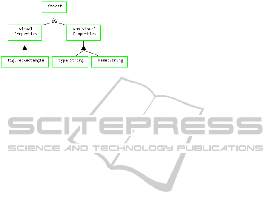
Figure 13: Defining visual and non-visual properties
this work.
4 CONCLUSIONS AND FUTURE
WORK
We have presented the principles of OPM/D, a meta-
modeling language, which is a subset of Object-
Process Methodology (OPM), for defining and creat-
ing DSMLs. The language is based on the graphical
language of OPM. To demonstrate the capabilities of
OPM/D, we have shown how to define a simplified
version of the OPM modeling language.
OPM/D can define not just OPM, but any DSML.
OPM/D allows for the visual definition of DSMLs in
two parts: a static model and a set of validation rules.
The static models define the elements of the language,
while the validation rules control what elements can
be added to the model and how they can be added, en-
suring that the resulting model of the defined DSML
is correct by construction at all times.
A prototype OPM/D based DSML language de-
signer and interpreter has been implemented as a
proof of concept for the idea presented in this paper
(without implementing all concepts). The prototype
is implemented using an open-source plugin on top
of the Eclipse platform, woth Eclipse EMF and GEF
technologies. The source code is available at github:
https://github.com/vainolo/OPClipse.
We plan on improving the stability, usability, and
functionality of the prototype in order to perform
comparative studies of the language and tool. We re-
quire this because using unstable and incomplete tools
in a study can create incomplete or incorrect results.
ACKNOWLEDGEMENTS
This research was supported by EU FP7 Project VI-
SIONAIR, Contract 262044.
We thank the OPClipse team: Eyal Heineman,
Kobi Ravid, Ilan Tchernovitz, Alez Zhitnitsky, and
Nimrod Shenhav for their help in reviewing the
OPM/D language definitions, and for making the im-
plementation possible.
REFERENCES
Bibliowicz, A. and Dori, D. (2011). A graph grammar-
based formal validation of object-process diagrams.
Software & Systems Modeling, 11(2):287–302.
Brooks, F. (1987). No silver bullet: Essence and accidents
of software engineering. IEEE computer, 20(4):10–
19.
Davis, J. (2003). GME: the generic modeling environ-
ment. In Companion of the 18th annual ACM SIG-
PLAN conference on Object-oriented programming,
systems, languages, and applications, OOPSLA ’03,
pages 83–83, New York, NY, USA. ACM.
Dori, D. (1999). Object-Process Methodology: A Holistic
Systems Paradigm. Springer-Verlag New York, Inc.,
Secaucus, NJ, USA.
Dori, D. and Choder, M. (2007). Conceptual modeling in
systems biology fosters empirical findings: the mRNA
lifecycle. PloS one, 2(9):e872.
Eclipse Foundation (2012a). Eclipse Graphical Editing
Framework - Version 3.8.2. http://www.eclipse.
org/gef/.
Eclipse Foundation (2012b). Eclipse Graphical Modeling
Framework - Release 1.6.0. http://www.eclipse.
org/modeling/gmp/.
Eclipse Foundation (2012c). Eclipse Graphiti - Release
0.8.2. http://www.eclipse.org/graphiti/.
Grundy, J. C., Hosking, J., Li, K. N., Ali, N. M., Huh, J.,
and Li, R. L. (2013). Generating Domain-Specific Vi-
sual Language Tools from Abstract Visual Specifica-
tions. IEEE Transactions on Software Engineering,
39(4):487–515.
JGraph Ltd. (2013). JGraphX. http://www.jgraph.com/
jgraph.html.
JUNG Framework Development Team (2010). JUNG -
Release 2.0.1. http://jung.sourceforge.net/
index.html.
MetaCase (2013). MetaEdit+ - Release 5.0. http://www.
metacase.com/.
Microsoft Corporation (2012). Visual Studio Visualization
and Modeling SDK 2012. http://archive.msdn.
microsoft.com/vsvmsdk.
Minas, M. (2004). VisualDiaGen - a tool for visually spec-
ifying and generating visual editors. In Applications
of Graph Transformations with Industrial Relevance,
Lecture Notes in Computer Science 3062, pages 398–
412. Springer Berlin Heidelberg.
Moody, D. (2009). The Physics of Notations: Toward a
Scientific Basis for Constructing Visual Notations in
Software Engineering. IEEE Transactions on Soft-
ware Engineering, 35(6):756–779.
Netbeans (2010). Netbeans Visual library 2.0. http://
platform.netbeans.org/graph/.
ICSOFT2013-8thInternationalJointConferenceonSoftwareTechnologies
478

OMG (2010). OMG Unified Modeling Language (OMG
UML) version 2.3, Superstructure.
OMG (2012). Object Constraint Language (OCL).
Reinhartz-Berger, I. and Dori, D. (2005). OPM vs. UML-
Experimenting with Comprehension and Construction
of Web Application Models. Empirical Software En-
gineering, 10(1):57–80.
Reinhartz-Berger, I., Dori, D., and Katz, S. (2002).
OPM/Webobject-process methodology for developing
web applications. Annals of Software Engineering,
13(1):141–161.
Selic, B. (2007). A Systematic Approach to Domain-
Specific Language Design Using UML. 10th
IEEE International Symposium on Object and
Component-Oriented Real-Time Distributed Comput-
ing (ISORC’07), pages 2–9.
Soffer, P. (2003). ERP modeling: a comprehensive ap-
proach. Information Systems, 28(6):673–690.
Somekh, J., Choder, M., and Dori, D. (2012). Concep-
tual model-based systems biology: mapping knowl-
edge and discovering gaps in the mRNA transcription
cycle. PloS one, 7(12):e51430.
The Standish Group International (2009). CHAOS Sum-
mary 2009 - The 10 Laws of CHAOS. Technical re-
port, The Standish Group International.
United States Government Accountability Office (2008).
Defense Acquisitions - Assessments of Selected
Weapon Programs. Technical report.
White, J., Schmidt, D. C., and Gokhale, A. (2007). Simpli-
fying autonomic enterprise Java Bean applications via
model-driven engineering and simulation. Software &
Systems Modeling, 7(1):3–23.
CreatingDomain-SpecificModelingLanguageswithOPM/D-AMeta-modelingApproach
479
