
EDEX: Entity Preserving Data Exchange
Yoones A. Sekhavat
1
and Jeffrey Parsons
2
1
Department of Computer Science, Memorial University of Newfoundland, St. John’s, Canada
2
Faculty of Business Administration, Memorial University of Newfoundland, St. John’s, Canada
Keywords: Data Exchange, Inherent Classification, Ambiguity Resolution, Ontology.
Abstract: Data Exchange creates an instance of a target schema from an instance of a source such that source data is
reflected in the target instance. The prevailing approach for data exchange is based on generating and using
schema mapping expressions representing high level relations between source and target. We show such
class level schema mappings cannot resolve some ambiguous cases. We propose an Entity Preserving Data
Exchange (EDEX) method that reflects source entities in the target independent of classification of entities.
We show EDEX can reconcile such ambiguities while generates a core solution as an efficient solution.
1 INTRODUCTION
Data exchange is the process of taking data
structured under a source schema, and generating an
instance that adheres to the structure of a target
schema. The prevailing approach for this process is
based on schema mappings – high level
specifications describing relationships between
database schemas (Bonifati et al., 2005); (Popa et
al., 2002). These specifications are usually
represented in a logical formalism capturing
relationships between database schemas independent
of implementations details. Many leading projects,
such as Clio (e.g., Fagin et al., 2009) have adopted
the schema mapping approach. Nevertheless,
because of semantic heterogeneities among data
sources, some ambiguous cases cannot be handled
using schema mappings.
We contend the problems of schema mapping
based approaches emerge from the assumption of
inherent classification (Parsons and Wand, 2000) in
information system design, by which every thing
modelled in a domain of interest is treated as an
instance of a class or entity (e.g., in an object-
oriented model or Entity Relationship model).
Although classification organizes knowledge about
things, real world objects do not inherently belong to
classes. According to ontological foundations about
the nature of things in the real world (Bunge, 1977),
things (specified in terms of a set of properties) exist
prior to and independent of their classification.
At the data level, there has been research on
data-centric heterogeneity reconciliation in data
exchange called entity resolution (Talburt, 2011).
Generally, entity resolution is used to clean data and
create a consistent view of data from heterogeneous
and conflicting representations by identifying
entities referring to the same real world object.
In spite of progress in schema level and data
level approaches for data exchange, semantic
heterogeneities are not completely resolved,
resulting in ambiguous cases in schema mappings
that lead to improper data exchange. Human
intervention is usually required to resolve these
ambiguities. We claim that, as schema mapping
expressions are bounded in class definitions, they do
not convey the whole semantics of data exchange.
Although data exchange based on schema mapping
has advantages in data exchange, neglecting entity
and data level heterogeneities can be problematic.
To address this gap, we suggest an entity preserving
approach that focuses on preserving source entities
in the target independent of classification. More
specifically, given a set of entities in the source, we
search for the best host relations that can reside
source entities as accurately as possible.
In conventional data exchange through schema
mapping, value correspondences as well as integrity
constraints are used to generate schema mapping
expressions. Then, such mappings are used to
generate target instances. However, in the entity
preserving approach, value correspondences are
directly used to find best relations that can reside
source entities without generating schema mappings.
221
Sekhavat Y. and Parsons J..
EDEX: Entity Preserving Data Exchange.
DOI: 10.5220/0004433902210229
In Proceedings of the 2nd International Conference on Data Technologies and Applications (DATA-2013), pages 221-229
ISBN: 978-989-8565-67-9
Copyright
c
2013 SCITEPRESS (Science and Technology Publications, Lda.)
The entity preserving approach proposed here
addresses this problem by considering property
correspondences and data level relations.
Parsons and Wand (2013) proposed a
preliminary schema mapping algorithm in which
conceptual models are used to semantically enhance
schema mappings for the sake of resolving
ambiguity. Although the results of experiments were
promising, the quality of final result depends
strongly on the quality of conceptual models.
However, EDEX does not rely on extra knowledge
to exchange data. In particular, the contributions of
this paper are as follows: (1) we show how data
exchange techniques based on schema mapping are
not capable of handling ambiguous cases; (2) we
propose the entity preserving approach for data
exchange which is a hybrid of data level and schema
level approach; (3) we propose a set of algorithms to
demonstrate the feasibility of implementing this
approach; and (4) we show the proposed approach
generates a core solution (Fagin et al., 2005) in data
exchange as the most efficient solution.
2 CLASS-BASED APPROACH
In practice, usually human intervention is required to
analyze and validate ambiguous schema mappings.
A mapping expression denotes an ambiguous case
when it can be interpreted more than one way, and
as a result, there is no unique way to generate the
target instance based on it (Alexe et al., 2008). One
important ambiguous case in data exchange occurs
when a generalization structure is implemented
using different techniques in source and target
schemas. A generalization can be realized by: 1)
allocating separate tables for super class and
subclasses, 2) allocating a separate table for each
subclass, and repeating the properties of the super
class in each subclass, 3) a single table including all
attributes of subclasses 4) a single table including all
attributes of subclasses by an additional property
indicating the subclass. A generalization relation can
result in ambiguity in data exchange through schema
mapping because other relations including functional
dependencies and self-reference can also realized
through the same technique (i.e., key/foreign key).
One important type of ambiguous schema
mapping occurs when a class in the source
simultaneously refers to more than one class in the
target where only one of them can be acceptable
based on the properties of instances of that class in
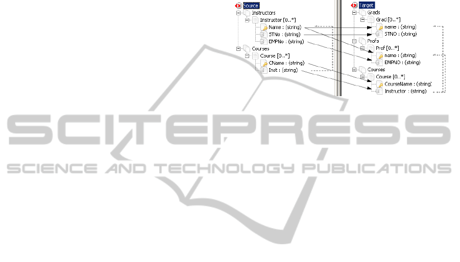
the source. For example, as shown in Figure 1, each
course is taught by an instructor. On the other hand,
in the target, a professor or a graduate student can be
an instructor of a course (arrows represent value
correspondence between properties and dashed lines
show referential integrity constraints). Given the
source and target schemas shown in Figure 1, the
following schema mapping expressions m
1
, m
2
and
m
3
are generated by ++Spicy (Marnette et al., 2011).
Figure 1: An example of a data exchange setting including
source and target schemas in ++Spicy.
m
1
: for each x
1
, x
2
, x
3
: Instructor (Name: x
1
,STNo: x
2
,
EMPNo: x
3
) → Grad (name: x
1
, STNO: x
2
).
m
2
: for each x
1
, x
2
, x
3
: Instructor (Name: x
1
, STNo: x
2
,
EMPNo: x
3
) → Prof (name: x
1
, EMPNO: x
3
).
m
3
: for each x
1
, x
2
, x
3
, x
4
: Instructor (Name: x
4
, STNo: x
2
,
EMPNo: x
3
), Course (CName: x
1
, Inst: x
4
) →
Course (CourseName: x
1
, Instructor: x
4
).
Using these mappings, given a source instance
[Instructor(I
1
,st
1
,null), Instructor(I
2
,null,emp
1
), Course(C
1
,
I
1
), Course(C
2
,I
2
)], ++Spicy generates the target
instance [
Grad(I
1
, st
1
), Grad(I
2
, null), Prof(I
1
, null),
Prof(I
2
, emp
1
), Course(C
1
, I
1
), Course(C
2
, I
2
)]. One
problem is that for each given tuple in Instructor,
two different mappings are generated, but only one
is acceptable according to STNo and EMPNo.
Intuitively, when STNO exists for an instructor in the
source, the corresponding record must be generated
in the Grad table in the target, but when EMPNO
exists for an instructor in the source, the
corresponding record must be generated in the Prof
table in the target. This ambiguity between m
1
and
m
2
generates redundant information in the target
while Grad(I
2
,null) and Prof(I
1
,null) are incorrect.
We next show how EDEX handles such ambiguities.
3 ENTITY PRESERVATION
According to Bunge’s ontology (Bunge, 1977), a
domain of interest includes a set of things each
possessing at least one property. In (Chen, 1976)
“entity” is defined as a “thing” which can be
distinctly identified. A specific person, company, or
event is an example of an entity. In relational
DATA2013-2ndInternationalConferenceonDataManagementTechnologiesandApplications
222
database theory, a tuple (row) of a table can
represent a particular entity where a primary key
uniquely identifies tuples within a relation. In
practice, a thing (physical object or a concept) can
be represented using one or more tuples in the
relational model. For example, characteristics of a
student, his/her department and university can be
stored all in a single student relation, where a tuple
represents student, department and university
entities. On the other hand, in a different database
schema, there may exist three different relations
where each tuple represents a particular entity.
Different configurations of relationships between
tuples and entities are a consequence of different
classification structures used in various schemas.
Such differences add complexity in data integration.
(Parsons and Wand, 2000) attribute such problems
to the assumption of inherent classification, wherein
every thing in the domain is an instance of a class.
To overcome the problem of different
classifications in the source and target, we propose a
solution that preserves entities in the source
regardless of classification. Our technique identifies
existing entities in the source and finds the best
host(s) for these entities, with the goal of maximum
information preservation and minimum redundancy.
Generally, a relational schema can be
represented using a directed graph G=(V, E) where
V={R
1
,…,R
n
} is a set of vertices representing
relations (tables) and E is a set of edges where each
edge shows a directed relation between the
referencing table to the referenced table.
Definition 1 (Schema Graph). Given a schema S, a
schema graph G=(V,E) is a directed graph that
defines relation joinability according to foreign key-
primary key relationships in S. It has a vertex R
i
for
each table R
i
∈
S and an edge from R
i
to R
j
for each
foreign key-primary key relationship from R
i
to R
j
.
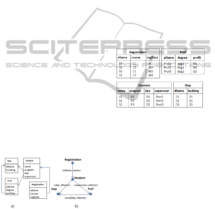
Figure 2: A relational schema (a) and the schema graph of
this relational schema (b).
In a schema graph G, each node has a name
representing a table in S, and a set of properties
specifying that table. Each edge from property p
1
of
R
i
to property p
2
of R
j
is labelled with a pair ‹p
1
, p
2
›
where p
1
references p
2
. An example of a schema
graph for relational schema in Figure 2(a) is shown
in Figure 2(b). Representing a schema using a
directed graph, indirect properties of relation R
i
can
be found in an acyclic graph representing ancestors
of R
i
that we define as a Relation Ancestors Tree.
Definition 2 (Neighbour Relation). We define
neighbours of a relation r denoted N(r) as a set of
relations that are referenced directly by r.
Consequently, there is an edge from r to any relation
in N(r). Accordingly, we define neighbours of a
tuple t as set of tuples referenced by t denoted N(t).
For example, N(Student) is {Dep, Prof}, and
given t as the first tuple of student instance in Figure
3, N(t) = {[(dName: D1), (building: B1)],[(pName:
prof1), (degree: deg1), (profDep:D1)]}.
Figure 3: An instance of the schema shown in Figure 2.
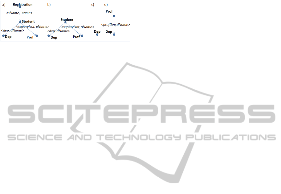
Definition 3 (Relation Ancestor Tree). A Relation
Ancestors Tree (RAT) of relation r denoted RAT(r) is
a sub graph of schema graph G with the root of r and
all paths from r to N(r), all paths from each relation
r
i
in N(r) to N(r
i
), and so on until adding a path does
not result in a cycle.
RAT(r) represents all ancestors of r that can be
extracted using the breath-first-search technique and
traversing from relation r to all ancestors of r where
that node is not already visited. Relation Ancestor
Tree for each relation of the schema and its schema
graph in Figure 2 is shown in Figure 4.
We distinguish between class level (generic) and
instance level (specific) properties. A relation in a
data model is represented in terms of a set of generic
properties while its tuples possess specific properties
represented as a set of property and value pairs (‹p,
v›). Possessing a specific property manifests
possessing a generic property. For example, (gender,
‘male’) and (gender, ‘female’) are two
manifestations of generic property gender. We use
P(r) to show properties of relation r (i.e., a set of
EDEX:EntityPreservingDataExchange
223
generic properties) and P(t) to represent properties
of tuple t (i.e., a set of specific properties ‹p
1
,v
1
›).
Figure 4: RATs for each relation of in Figure 2.
Drilling down a tuple from its foreign key(s) to
corresponding tuples in referenced relations, it is
possible to extract indirect properties in neighbour
relations. For example, given the Student relation in
Figure 3, {(name, s1), (program, p1), (dep, D1),
(supervisor, Prof1)} is the set of properties of the
first tuple of Student. On the other hand Student
references Department through (dep, D1), where
{(dName, D1), (building, B1)} can be considered
indirect properties of this student. Accordingly,
properties of supervisor {(pName, prof1), (degree,
deg1), (profDep, D1)} can also be considered as
indirect properties of this student. In addition, each
professor tuple references a particular department
where properties of that department can be
considered as indirect properties of that professor.
Definition 4 (Tuple Ancestors Tree). A Tuple
Ancestors Tree of a tuple t denoted TAT(t) is a tree
with the root of t and all paths from t to N(t), all
paths from each t
i
in N(t) to N(t
i
) and so on until
adding a path does not result in a cycle.
Using the concept of indirect properties, we
introduce and define the concept of super entity.
Definition 5. A Super Entity of a tuple t from
relation r (i.e., denoted SE(t)) is a set of specific
properties of t as well as all indirect properties of
that t that are accessible from TAT(t). Formally,
SE(t) = P(t) U P(TAT(t)) where P(TAT(t)) is the set
of all specific properties in TAT(t).
Intuitively, if t is a tuple of relation r with no
referring relation, then super entity of t has the same
set of properties as t. A super entity shows complete
information of a tuple including all direct and
indirect properties regardless of the classification in
a schema. Generating super entities can be
considered as a declassification process that shows
information content of a data source regardless of
any structure and only through a set of properties.
We argue that such flat structures can be used for
data exchange without difficulties in handling the
structure of classes in the source.
3.1 Entity-preserving Data Exchange
EDEX is performed in four steps: (1) extract all
super entities in the source schema; (2) prune
redundant entities; (3) select the best host relations
for these entities in target; and (4) move the pruned
super entities to their proper host tables.
Step 1 (Super Entity Generation). The first
step towards data exchange in EDEX is extracting
all super entities, as they hold complete information
regarding source entities independent of
classification. In a schema graph, an edge between
nodes v
1
and v
2
is a foreign key from a column of v
1
to a primary key of v
2
. Each foreign key of a tuple
references at most one tuple of the referenced table
(where more than one foreign key references the
same table, the tree includes more than one edge
with different labels between the nodes).
A super entity regarding a tuple t is a flat
structure that can be defined as a view over all
ancestors of t. The Relation Ancestor Tree RAT(r) is
a structure showing how this view can be built
regarding tuples of relation r. In order to build
RAT(r), node r is selected as the root. Then using the
schema graph, all outgoing edges from r and their
corresponding nodes R are connected to r. For each
node r
i
in R, their outgoing edges and corresponding
nodes are added to r
i
if they do not already exist in
RAT(r). The process continues until there is no edge
to add or adding an edge results in a loop in RAT(r).
Once Relation Ancestor Trees of all relations in a
schema are extracted, super entities can be extracted
using view statements generated by post-order
traversing these trees. In each step, leaves are joined
with parent nodes. The output of this traverse is a
nested view statement representing how nodes are
joined. A Relation Ancestor Tree is traversed in
post-order manner such that in each step, a join
between a child and its parent is formed. For the four
relational ancestor trees shown in Figure 4, the
following view statements are generated.
Dep: Dep
Prof: Prof
⋈
Dep
Student: (Student
⋈
Dep)
⋈
Prof
Registration: Registration
⋈
((Student
⋈
Dep)
⋈
Prof)
Applying these view statements on the source
instance (shown in Figure 3) results in generating
the set of super entities listed in Figure 5. In addition
to ‹property, value› pairs, the source of each entity is
also indicated for each super entity.
Step 2 (Pruning Redundant Information).
The set of super entities must be pruned to eliminate
repetitive information. To this end, we introduce and
DATA2013-2ndInternationalConferenceonDataManagementTechnologiesandApplications
224

use the concept of distinct super entity. A distinct
super entity is a super entity possessing at least one
property that does not exist in other super entities of
an instance. To extract a list of distinct super
entities, a pruner algorithm is proposed to check if
all elements of a super entity (the set of ‹property,
value› pairs specifying that super entity) exist in at
least one other super entity.
e
1
: {(dName, D1), (building, B1)}, src = {Dep}
e
2
: {(dName, D2), (building, B1)}, src = {Dep}
e
3
: {(dName, D3), (building, B2)}, src = {Dep}
e
4
: {(name, S1), (program, P1), (dep, D1),(dName, D1),
(building, B1), (supervisor, prof1), (pName, Prof1),
(degree, deg1), (profDep, D1)}, src = {Student}
e
5
: {(name, S2), (program, P2), (dep, D2), (dName,
D2),
(building, B1), (supervisor, prof2), (pName, Prof2),
(degree,deg1), (profDep, D1)}, src = {Student}
e
6
: {(name, S3), (program, P3), (dep, D2), (dName,
D2),
(building, B1), (supervisor, prof3), (pName, Prof3),
(degree, deg2), (profDep, D2)}, src = {Student}
e
7
: {(sName, S1), (name, S1), (program, P1), (dep,
D1),(dName, D1),(building, B1), ((supervisor,
prof1),
(pName, Prof1), (degree, deg1), (profDep, D1),
(course,
C1), (regDate, dt1)}, src ={Registration}
e
8
: {(sName, S2), (name, S2), (program, P2), (dep,
D2),(dName, D2), (building, B1), (supervisor,
prof2),
(pName, Prof2), (degree,deg1), (profDep, D1),
(course,
C2), (regDate,dt2)}, src ={Registration}
e
9
: {(sName, S2), (name, S3), (program, P3), (dep,
D2),(dName, D2), (building, B1), (supervisor, prof3),
(pName, Prof3), (degree, deg2), (profDep, D2),
(course,
C1), (regDate,dt3)}, src ={Registration}
e
10
: {(sName, S1), (name, S1),(program, P1), (dep,
D1),(dName, D1), (building, B1), (supervisor, prof1),
(pName, Prof1), (degree, deg1), (profDep,
D1),(course,
C2), (regDate, dt4)}, src ={Registration}
e
11
: {(pName, Prof1), (degree, deg1), (profDep, D1),
(dName, D1), (building, B1)}, src ={Prof}
e
12
: {(pName, Prof2), (degree, deg1), (profDep, D1),
(dName, D1), (building, B1)} , src ={Prof}
e
13
: {(pName, Prof3), (degree, deg2), (profDep, D2),
(dName, D2), (building, B1)} , src ={Prof}
Figure 5: Super entities generated for RATs in Figure 4.
To avoid brute force search, the pruner algorithm
for a given super entity checks only super entities
extracted from neighbours of the source relation of
that super entity. As a result, given a schema graph,
the algorithm searches for inclusion only among
super entities tagged as neighbours of the source of
that super entity. For example, for super entities
extracted from Dep, only instances of Student and
Prof are checked (these are the only relations
referencing Dep). Accordingly, only super entities
extracted from Registration are checked for each
super entity extracted from Student. The order of
checking super entities for inclusion can be
problematic as different checking orders may result
in different output. To address this problem, once an
inclusion is found, instead of physical deleting, the
item is marked as “deleted”. Actual deleting is
performed once all inclusion tests are performed.
In our example, the Super Entity Pruner
algorithm removes super entities e
1
as it is
completely included in e
4
. e
2
is removed because of
inclusion in e
5
(and e
6
). Accordingly, {e
1
, e
2
, e
3
} are
checked for inclusion in {e
4
, e
5
, e
6
, e
11
, e
12
, e
13
}. In
the same way, {e
4
, e
5
, e
6
} are checked for inclusion
in {e
7
, e
8
, e
9
, e
10
, e
12
}. Nothing is checked for e
7
, e
8
,
e
9
, e
10
as their source (i.e., Registration) is not
referenced by a relation in the schema graph.
─────────────────────────────────────
Algorithm 1: Super Entity Pruner.
─────────────────────────────────────
Input: a list of super entities suprEnt
a schema graph regarding a source schema G=(V, E)
Output: a pruned list of super entities
1: foreach super entity e
1
in suprEnt
2: src
1
= the source of e
1
3: refNeighbors = a set of nodes in G referencing src
1
4: // there is no node v
i
in V such that v
i
is referencing src
1
5: If (refNeighbors == null)
6: continue;
7: foreach super entity e
2
in suprEnt
8: src
2
= the source of e
2
9: If (refNeighbors contains src
2
)
10: If (e
1
is included in e
2
)
11: mark e
1
as “deleted”
12: foreach super entity e
1
in suprEnt
13: If (remove e
1
from suprEnt if e
1
is marked as “deleted”)
─────────────────────────────────────
Step 3 (Host Relation Selection). Selecting
target host relations requires considering several
issues. First, the same concepts may be shown using
different representations and as a result, two
different properties can represent the same concept
in the source and target. To connect source and
target, we use property correspondences in form of
‹p
1
, p
2
› representing correspondence between
property p
1
in source and property p
2
in the target.
Each correspondence shows that an attribute of the
target is semantically related to an attribute in the
source. In our approach, value correspondences are
directly used to select best hosts regarding source
EDEX:EntityPreservingDataExchange
225
entities regardless of schema mapping expression.
We consider conditions for selecting best host for
source entities: (1) Completeness means the residing
hosts must be able to recover properties of source
entities in the target as complete as possible; (2)
Non-redundancy means no repetitive information is
transferred to the target. To satisfy these conditions,
we propose a host selection algorithm (Algorithm
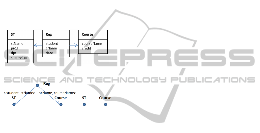
II). We use the target schema in Figure 6 and the
following value correspondences
{name ↔ stName,
program ↔ prog, dName ↔ dpt, supervisor ↔
supervisor, course ↔ courseName, regDate ↔ date}
between this schema and source schema in Figure 2
to explain the host selection algorithm.
Figure 6: The target schema residing the source instance.
Figure 7: RATs constructed for each relation in Figure 5.
To select the best hosts for source entities, we
consider Relation Ancestor Trees in the target as
structures that can reside super entities of the source.
Then, a RAT correspondence to each relation in the
target must be extracted. We need to check which
structure can properly reside super entities of source.
For the target shown in Figure 6, the RATs
constructed for each relation are shown in Figure 7.
We assume existence of a unique property name
for each property (as each property can be named
using the triple (dbName, tableName, proprtyName).
We form a hash table from value correspondences
where, for each correspondence ‹p
1
, p
2
›, the
corresponding property of a given property is
accessible. The best Relation Ancestor Tree to reside
given super entity would be the one that has the
maximum number of properties (class-level
properties) matching the properties (specific
properties) of that super entity. Among those RATs
with maximum number of matching properties, a
RAT with minimum number of total properties is
selected as this RAT holds minimum number of
unrelated properties (see Algorithm II).
─────────────────────────────────────
Algorithm 2: Host RAT selector.
─────────────────────────────────────
Input: A list of source super entities suprEnt
Schema graph regarding the target schema GT=(V
T
, E
T
)
Hash Table htCorr with target properties as keys and
source properties as values
Output: The list of super entities marked with host names
1: tgt_RAT_collection ← the set of RATs for each relation in GT
2: tgt_property_collection = a collection holding a set of
3: properties for each RAT(r)
4: foreach super entity e in suprEnt
5: matchingCount = new HashTable();
6: foreach property p in e
7: foreach RAT r in tgt_RAT_collection
8: If htCorr[p] in tgt_property_collection[r]
9: matchingCnt[r]++; //values are initialized with 0
10: If there is a single maximum value in matchingCnt
11: assign RAT (r) corresponding to this value to e
12: Else If more than one r exists with max matchingCnt
13: select RAT (r) with minimum number of properties and
14: assign it to e
15: return suprEnt
────────────────────────────────────
When no TRV with any matching property is
found, this indicates the target schema is not capable
of hosting this super entity. Otherwise, matching at
least one property ensures residing that super entity.
Given the set of super entities extracted in Step 2,
the following host RATs are selected for each super
entity as follows:
e
3
→ ST, e
4
→ ST, e
5
→ ST, e
6
→ ST,
e
7
→Reg, e
8
→ Reg, e
9
→ Reg, e
10
→ Reg,
e
11
→ ST, e
12
→ ST, e
13
→ ST
Step 4 (Entity Residing). The final step of EDEX
is residing super entities extracted from the source in
host RATs. Although super entities completely
included in other super entities are removed by the
pruner algorithm in step 2, there still may exist super
entities containing information about the same
entity. For example, e
1
and e
2
may contain
information about the same department. In data
exchange, such information should refer to the same
entity in the target to avoid entity redundancy. To
address this problem, we use target egds to encode
primary key constraints in the target. We use these
constraints to avoid inserting the same entities with
different identifications by checking primary keys.
When a request to insert in target relations is made,
the algorithm checks if information about the unique
properties already exists. If so, the insertion is
aborted. Otherwise the insertion is performed.
One issue that must be considered in residing of
super entities is that information regarding each
ancestor must be inserted before information of its
descendants, as each child has at least one property
referring to the primary key of its parent. In
particular, the structure of host RAT can provide the
DATA2013-2ndInternationalConferenceonDataManagementTechnologiesandApplications
226

proper order of information insertion. For this, a
post-order traversal of each host RAT ensures
insertion in ancestors before inserting descendants.
The details of generating insertion statements to
reside a super entity in a host RAT is shown in
Algorithm III. Insertion statements generated by this
algorithm can be easily transformed to SQL
insertion statement as it is performed in our EDEX
prototype. The host RAT is traversed in the post-
order manner and the nested structure for insertion is
created. For example, given a host RAT for Reg
relation, the following expression is generated
representing the order of insertions.
ex
1
:Reg(student (ST: stName, prog, dpt, supervisor),
cName (Course: courseName, credit), date)
This structure shows the order of inserting properties
given properties of a super entity. To generate
insertion statements, we start from greatest
ancestors. In our example, ex
1
prescribes three
insertion statements with the order of ST, Course
and Reg. First, two set of properties P
1
= (stName,
prog, dpt, supervisor) and P
2
= (courseName, credit)
are inserted as two nested set of properties. For
example, for a super entity e
7
(e
7
: {(sName, S1),
(name, S1), (program, P1), (dep, D1),(dName,
D1),(building, B1), ((supervisor, prof1), (pName,
Prof1), (degree, deg1), (profDep, D1), (course, C1),
(regDate, dt1)}) with Reg as a target host, the
algorithm first checks if there is a common property
between properties of e
7
and P
1
. In this case
{stName, prog, dpt, supervisor} are selected as
common properties. Value correspondences are
taken into account in finding common properties
(e.g., dName in source corresponds to dpt in target).
Then, regarding the primary key of the
corresponding target relation ST (i.e., stName), the
ST relation is checked to see if information related to
this student is already inserted in this table. If not, a
tuple covering these properties is inserted and the
primary key of this tuple is returned as a reference.
If this tuple is already inserted, no insertion is
generated and stName is returned as a reference. In
the same way, for the second nested set of properties
(Course: courseName, credit), courseName is
identified as common property between e
7
and ex
1
.
Then, Course table is checked to find if information
regarding cName=C
1
is already inserted to Course.
Finally, since there is no other nested statement, an
insertion statement for Reg is generated.
Applying target egds may result in losing entities
of source because inserting a tuple into a table may
not be possible due to integrity constraints. For
example, since information about students and
departments is stored in the same table with stName
as a primary key, existence of a department depends
on existence of a student. In our example, e
3
cannot
be inserted to ST because there is no student who is
assigned to this department. This is a trade-off
between data consistency and data completeness
where a designer may relax some target egds to gain
complete data exchange. However, the algorithm we
propose prioritises integrity constraints and does not
allow breaking any target egd constraint. An
important benefit of this feature is ensuring
generation of the core solution as the most efficient
solution in data exchange, as discussed next.
─────────────────────────────────────
Algorithm 3: Entity Residing.
─────────────────────────────────────
Input: Super entity e = {‹p
1
, v
1
›‹p
2
, v
2
›,...}
Host Relation Ancestor Tree RAT(r)
1: ex = the nested expression generated from the post-order
2: traversal of RAT(r)
3: Seq = the order of relations from ex for insertion such that
4: inner parentheses come before outer parenthesis
5: HtReferences = null
6: foreach relation r in Seq
7: CP= common properties of e and r
8: If CP is null then
9: continue;
10: Else If information regarding CP is already inserted in r
11: return related reference from HtReferences.
12: Else
13: insert the tuple related to e in r, add the reference to
14: HtReferences, and return this reference
─────────────────────────────────────
4 EDEX AND CORE SOLUTION
(Bonifati et al., 2011) define a desirable target
instance as a legal instance satisfying
correspondences between source and target and
integrity constraints in the target. Such an instance
contains all source information while no information
is reported twice. In the schema mapping based data
exchange, a mapping scenario is denoted M=(S, T,
Σ
st
, Σ
t
) where S is a source schema, T is a target
schema, Σ
st
is a set of s-t tgds (i.e., source-to-target
dependencies) and Σ
t
is a set of target constraints. If
I is an instance of S and J is an instance of T, then J
is called a solution for M and I if I and J satisfy Σ
st
,
and J satisfies Σ
t
. Formally, this is shown in form of
J
∈
Sol(M, I) iff ‹I, J› satisfies dependencies in Σ
st
∪
Σ
t
(i.e., ‹I, J›
⊨
(Σ
st
∪
Σ
t
)). Given M= (S, T, Σ
st
, Σ
t
),
multiple solutions may exist given a source instance
because each tgd only states an inclusion constraint
without indicating the content of a target instance.
In (Fagin et al., 2005) the concept of universal
solution is proposed that has with several good
properties. To formalize the notion of universal
solution, we need to introduce homomorphism
EDEX:EntityPreservingDataExchange
227

among two solutions. Let Const the set of all
constant values that may occur in source instances,
and Var an infinite set of variables (called labeled
nulls) such that Var ∩ Const = ∅. Each element of a
tuple t={a
1
,a
2
,...,a
n
} over a relation from an instance
is a member of Const
∪
Var.
Given K
1
and K
2
two instances over a relational
schema R with values in Const ∪ Var, A
homomorphism h: K
1
→ K
2
is a mapping from
Const
∪
Var (K
1
) to Const
∪
Var (K
2
) such that: (1)
h(c) = c for every c
∈
Const; (2) for every fact R
i
(t)
of K
1
, we have that R
i
(h(t)) is a fact of K
2
where, if t
= (a
1
,...,a
n
), then (t)= (h(a
1
),..., h(a
n
)).
A universal solution for I is a solution J such that
for every solution J´ for I, there exists a
homomorphism h: J → J´. Among universal
solutions, the solution with smallest size is called the
core solutions (Fagin et al., 2005). Because of the
minimality and uniqueness of the core solution
among universal solutions, this solution is
considered as an ideal solution for data exchange.
Formally, a target instance J among universal
solution is called a core solution if there is no proper
subinstance J´
⊆
J such that there is a
homomorphismh: J→J´.We claim that EDEX is a
schema mapping independent technique that
generates the core solution. Theorems 1, 2 and 3
elaborate hypotheses regarding this claim (Proof is
available from authors upon request).
Theorem 1: Given a set of correspondences Σ
st
,
EDEX generates a valid target solution.
Theorem 2: Given a source instance I, EDEX
generates a universal solution in the target.
Theorem 3: EDEX generates the core solution.
5 RELATED WORK
The prevailing approach in data exchange uses
schema mapping to generate the target instance.
Alongside studies on practical tools and algorithms
for schema mapping generation, there have been
theoretical studies on data exchange to provide a
solid foundation for data exchange (Fagin et al.,
2005). Generated by many schema mapping systems
such as Clio (Fagin et al., 2009); (Popa et al., 2002)
and HePToX (Bonifati et al., 2005) universal
solutions are preferred as they are the most general
solution covering the entire space of valid solutions.
On the other hand, generating core solutions as a
minimal universal solution is considered a natural
requirement in data exchange (Gottlob and Nash,
2008); (Fagin et al., 2005). In pre-processing
approaches such as ++Spicy (Marnette et al., 2011),
schema mapping expressions are rewritten such that
refined mappings directly generate the core solution.
To resolve ambiguous mappings, Muse (Alexe et
al., 2008) allows a mapping designer to select
desired mapping among alternative interpretations of
an ambiguous mapping. As an alternative option,
(Qian et al., 2012) proposed a sample-driven schema
mapping based on the technique that automatically
constructs schema mappings from sample target
instances provided by users. In Eirene (Alexe et al.,
2011) data examples are used to refine schema
mappings rather than generating mapping
expressions. (Sekhavat and Parsons, 2013) proposed
a technique in which schema mapping expressions
are enhanced using conceptual models. The main
drawback of this approach is the difficulty of
designing a global conceptual model.
6 CONCLUSIONS
In this paper, we showed that class based mapping
expressions are not capable of handling many
ambiguous cases in data exchange. We attributed
this problem to the assumption of inherent
classification in information systems. To address this
problem, we proposed an entity preserving approach
(EDEX) for data exchange in which the focus is on
preserving source entities in the target no matter to
what class they belong in the source. We introduced
the concept of super entities to capture indirect
properties of entities. We showed unlike many
schema mapping based data exchange systems,
EDEX can resolve ambiguous cases. In addition,
EDEX can directly generate the core solution as the
most efficient and accurate solution for data
exchange. Several interesting issues remain open.
Developing mapping language expressing relations
between source and target independent of
classification is of particular interest.
REFERENCES
Alexe, B., Chiticariu, L., Miller, R. J., & Tan, W., 2008.
Muse: Mapping understanding and design by example.
In ICDE'08, IEEE International Conference on Data
Engineering.
Alexe, B., ten Cate, B., Kolaitis, P. G., & Tan, W., 2011.
Eirene: Interactive design and refinement of schema
mappings via data examples. VLDB Endowment.
Bonifati, A., Mecca, G., Papotti, P., & Velegrakis, Y.,
2011. Discovery and correctness of schema mapping
DATA2013-2ndInternationalConferenceonDataManagementTechnologiesandApplications
228

transformations. Schema Matching and Mapping.
Bonifati, A., Chang, E. Q., Lakshmanan, A. V. S., Ho, T.,
& Pottinger, R., 2005. HePToX: Marrying XML and
heterogeneity in your P2P databases. In VLDB'05,
International Conference on Very Large Data Bases.
Bunge, M., 1977. Treatise on basic philosophy: Vol. 3:
Ontology I: The furniture of the world.
Chen, P. P., 1976. The entity-relationship model-toward a
unified view of data. ACM Transactions on Database
Systems.
Fagin, R., Haas, L. M., Hernández, M., Miller, R. J., Popa,
L., & Velegrakis, Y., 2009. Clio: Schema mapping
creation and data exchange. Conceptual Modeling:
Foundations and Applications.
Fagin, R., Kolaitis, P. G., & Popa, L., 2005. Data
exchange: Getting to the core. ACM Transactions on
Database Systems.
Gottlob, G., & Nash, A., 2008. Efficient core computation
in data exchange. Journal of the ACM.
Haas, L. M., Hentschel, M., Kossmann, D., & Miller, R.
J., 2009. Schema and data: A holistic approach to
mapping, resolution and fusion in information
integration. In ER'09, International Conference on
Conceptual Modeling.
Marnette, B., Mecca, G., Papotti, P., Raunich, S., &
Santoro, D., 2011. ++Spicy: An open-source tool for
second-generation schema mapping and data
exchange. In VLDB'11, International Conference on
Very Large Data Bases.
Parsons, J., & Wand, Y., 2000. Emancipating instances
from the tyranny of classes in information modeling.
ACM Transactions on Database Systems.
Popa, L., Velegrakis, Y., Hernández, M. A., Miller, R. J.,
& Fagin, R., 2002. Translating web data. In VLDB'02,
International Conference on Very Large Data Bases.
Qian, L., Cafarella, M. J., & Jagadish, H., 2012. Sample-
driven schema mapping. In SIDMOD'12, International
Conference on Management of Data.
Sekhavat, Y. A., & Parsons, J., 2013. SESM: Semantic
enrichment of schema mappings. In DESWEB'13,
Data Engineering Meets the Semantic Web.
Talburt, J. R., 2011. Entity resolution and information
quality Morgan Kaufmann.
EDEX:EntityPreservingDataExchange
229
