
Gap Analysis in Enterprise Architecture using Semantic Web
Technologies
Philipp Diefenthaler
1,2
and Bernhard Bauer
2
1
Softplant GmbH, Munich, Germany
2
Institute for Software & Systems Engineering, University of Augsburg, Augsburg, Germany
Keywords:
Enterprise Modelling, Gap Analysis, Semantic Web.
Abstract:
Enterprise architectures (EA) can be used for analyses in different ways and thus can support the decision
making process that has to cope with an increasing number of changes, the clarification of the extent of changes
and the complexity of these changes. A gap analysis is used in the context of EA to identify differences
between two states of an EA. Formal models of an EA allow tool support and the visual representation of
these models. This paper shows how a gap analysis can be performed using semantic web technologies on a
high-level current and target state of an EA. With the results of the gap analysis and a detailed current state it
is possible to show a migration path from the current state of the EA to a plan or target EA.
1 INTRODUCTION
An enterprise architecture (EA) can be used to rep-
resent the enterprise and its underlying information
technology in models that can support decision mak-
ing. Such EA models cover aspects from busi-
ness, processes, integration, software and technology
(Winter and Fischer, 2006). To cope with the inherent
complexity of the elements’ relationships, the num-
ber of stakeholders involved, and the change of in-
ternal and external conditions it is crucial for enter-
prises to use a managed approach to steer and control
the redesign of the EA. In order to be able to plan the
change it is necessary to have a plan basis, i.e. the cur-
rent state of the EA, and to know the goal of planning
activities, i.e. the target state of the EA. According to
Pulkkinen and Hirvonen (2005); Pulkkinen (2006) the
planning activities using an EA take place at differ-
ent decision levels. These levels are named enterprise
level, domain level and system level. Each of them
vary in detail and levels of abstraction seem to be in-
evitable (Pulkkinen, 2006). The need to change and
the resulting moving target (Niemann, 2006) is a chal-
lenge EA planning has to cope with and can be sup-
ported by tools. In practice there exist already several
tools for EA planning. However, none of them pro-
vides the functionality described in this paper. This
paper shows how the gap analysis can be performed
on two high-level EA models representing the current
and target state of an EA using semantic web tech-
nologies. Furthermore, it is shown how successor re-
lationships can be added. Starting with the identified
gaps, successor relationships and a detailed current
EA state at hand it is possible to support the migra-
tion to a detailed target state.
The paper is structured as follows: Section 2 gives
a short overview for using EA models for planning
purposes and shortly introduces semantic web tech-
nologies relevant for this paper. In Section 3 related
work relevant for the gap analysis is presented. The
concept how to detail the target state by using the gap
analysis and semantic web technologies is presented
in Section 4. The paper closes in Section 5 with a
summary and outlook for further research.
2 FOUNDATIONS
This section gives an introduction to the foundations
of enterprise architecture models and their usage for
planning purposes. Furthermore, semantic web tech-
nologies and two of their key technologies relevant
for this paper are presented.
2.1 Enterprise Architecture Models
According to Buckl and Schweda (2011) enterprise
architecture management (EAM) is a management cy-
cle that consists of the phases plan, do, check and act
211
Diefenthaler P. and Bauer B..
Gap Analysis in Enterprise Architecture using Semantic Web Technologies.
DOI: 10.5220/0004439702110220
In Proceedings of the 15th International Conference on Enterprise Information Systems (ICEIS-2013), pages 211-220
ISBN: 978-989-8565-61-7
Copyright
c
2013 SCITEPRESS (Science and Technology Publications, Lda.)

(Deming Cycle (Deming, 1994)). The plan phase is
concerned with developing change proposals that are
implemented in the do phase. Within the check phase
differences between intended and actually achieved
results are controlled. Based upon the results from
the check phase the act phase provides input to the
plan phase by supplying information for the next plan
phase. Models of an enterprise, as an abstraction from
reality, can support the plan phase as part of an en-
terprise architecture management approach (Aier and
Gleichauf, 2010a; Buckl et al., 2009).
A model of an EA can be used to represent the ar-
chitecture of an enterprise at different points in time
(Buckl and Schweda, 2011). The current state of the
architecture is a documented state at the present point
in time and serves as a starting point for defining a
target state. The target state represents a goal state
in the future which can be used to guide the develop-
ment of an enterprise architecture from the current to-
wards a target state. The development of a target state
highly depends on the enterprises’ EA goals. It is in-
fluenced by business requirements, strategic goals and
IT objectives like master data consolidation, improve
the flexibility of IT and drive the coverage of standard
platforms Hanschke (2009). Which factors and how
exactly they influence the target architecture highly
depends on the architecture method applied and how
it is integrated into the enterprise. Between the cur-
rent and target state it is possible to develop planned
states which can represent alternative states, e.g. two
planned states exist for the same point in time, or are
successors of the current and predecessor states of the
target. A gap analysis, sometimes also referred to as
delta analysis, is the comparison between two differ-
ent states of an enterprise architecture that is used to
clarify the differences between those two states. Dif-
ferent states that can be compared are current to tar-
get, current to planned, planned to target and planned
to planned (Buckl and Schweda, 2011).
2.2 Semantic Web Technologies in a
Nutshell
Semantic web technologies can be used to integrate
heterogeneous data sets and formalize the underly-
ing structure of the information to allow a machine
to understand the semantics of it (Shadbolt et al.,
2006). The World Wide Web Consortium (W3C)
provides a set of standards to describe an ontology
and to query it. Two standards are of relevance
for this paper: firstly, the Web Ontology Language
(OWL) (Bechhofer et al., 2004), which is capable of
describing the state of an EA model and secondly,
the SPARQL Query Language for RDF (SPARQL)
(Prud’hommeaux and Seaborne, 2008), which allows
querying these models. The Resource Description
Framework (RDF) (Manola et al., 2004) is a basis for
both standards, as OWL ontologies can be represented
as RDF graphs and can be accessed via SPARQL. A
RDF graph consists of triples of the form ‘subject,
predicate, object’. Every information in an ontology
can be identified by a resource identifier which con-
tains a namespace, which allows for example distin-
guishing between a bank in a financial context and
a bank of a river. Semantic web technologies have
already been applied to several different applications
that range from semantic business process modelling
(Lautenbacher, 2010) to diagnosis of embedded sys-
tems (Grimm et al., 2012). First implementations
based upon semantic web technologies for EA man-
agement already exist from TopQuadrant with its Top-
Braid Composer
1
and Essential Project
2
.
3 RELATED WORK
In this section related work for gap analysis is intro-
duced. As a starting point the technical report ‘On
the State of the Art in Enterprise Architecture Man-
agement Literature’ (Buckl and Schweda, 2011) was
taken, as they consider the gap (delta) analysis as part
of the different approaches. The focus in this paper is
on using the gap analysis as method to detect differ-
ences between a current and a target state. Besides the
listed approaches in the technical report an approach
from the University of Oldenburg was identified as
relevant for the purpose of this paper.
3.1 Gap Analysis - University of
Oldenburg
The Institute for Information Technology of the Uni-
versity of Oldenburg presents a tool supported ap-
proach for performing a gap analysis on a current
and ideal landscape (Postina et al., 2009; Gringel and
Postina, 2010). The approach is tightly coupled to
the Quasar Enterprise (Engels et al., 2008) approach,
which can be used to develop service-oriented appli-
cation landscapes. In order to be able to perform their
gap analysis it is necessary to model the current ap-
plication landscape consisting of current components,
current interfaces, current operations and business ob-
jects. The ideal landscape is modelled with ideal
1
www.topquadrant.com/docs/whitepapers/
WP-BuildingSemanticEASolutions-withTopBraid.pdf
2
http://www.enterprise-architecture.org/
ICEIS2013-15thInternationalConferenceonEnterpriseInformationSystems
212

components, ideal interfaces, ideal operations and do-
mains. Based on these two models the tool is capable
to generate a list of actions that would, if all were ap-
plied, result in the ideal landscape. Within the paper
the suggested procedure for selecting actions is to al-
low an architect to select certain actions that result
in a target. Furthermore, the tool is capable to pro-
vide metrics for quantitative analysis of the applica-
tion landscape. Gringel and Postina state that the gap
analysis needs a “detailed level of description when
it comes to modelling both landscapes” ((Gringel and
Postina, 2010), p. 283) and as a result the “data neces-
sary to perform gap analysis on the entire application
landscape on a detailed level considering operations is
overwhelming” (Gringel and Postina (2010), p. 291).
How the different actions interfere with each other is
not considered and actions can only be provided if an
ideal landscape with all details has been modelled.
3.2 Gap Analysis - University of
St. Gallen
The EAM approach of the University of St. Gallen
uses the gap analysis as a starting point to plan the
transformation by identifying the differences between
two states considering changed elements. Aier and
Gleichauf distinguish between a macro and micro
level of enterprise models, e.g. a current and target
state, whereas on the micro level detailed informa-
tion about successor relationships of the elements is
available (Aier and Gleichauf, 2010b). This informa-
tion is kept in a so called transformation model. Fur-
thermore, information about changed relationships is
part of the transformation model. Aier and Gleichauf
(2010a) suggest to compare the graphs of the differ-
ent architecture states to gain information about nec-
essary changes. Afterwards, it is possible to derive
six different successor relationships between the ele-
ments of the different model states and store this in-
formation in a transformation model. How the succes-
sor relationships are derived or if they are modelled
manually is not described. Furthermore, changed de-
pendencies are not considered as part of the changes.
3.3 Gap Analysis - Strategic IT
Managment by Hanschke
The ‘Strategic IT Management’ (Hanschke, 2009) ap-
proach is intended to serve as a toolkit for EAM by
providing best-practices derived from work experi-
ence. After a target state has been modelled and
agreed upon the gap analysis is used to detect dif-
ferences between the current and target state. The
gap analysis is performed on the basis of process sup-
port maps visualizing which information systems sup-
port which business processes (x-axis) and which cus-
tomer group (y-axis) the information systems are as-
signed to. For a more fine grained gap analysis Han-
schke suggests to additionally add information about
interfaces and information objects of the information
systems. Afterwards, for each gap possible actions
to close the gap are considered. These actions range
from introducing a new information system, adding or
reducing functionality of an existing information sys-
tem, changing or adding interfaces to the shut down
of information systems and interfaces. Based upon
the results of the gap analysis and derivation of ap-
propriate actions it is necessary to clarify dependen-
cies between the actions, bundle the actions and create
planned states as recommendations for change. As far
as we were able to verify the limitations of the tool
and approach it is not possible to create suggestions
for a detailed target state.
4 USING SEMANTIC WEB
TECHNOLOGIES FOR GAP
ANALYSIS
The presented example in this section is similar to the
examples given in (Hanschke, 2009) as these provide
detailed information on the current state and high-
level information of the current and target state. The
goal of the proposed approach is to deliver a more de-
tailed target state by making suggestions to a user how
a detailed target state could look like, derived from the
gaps identified in the high level states and a detailed
current state. The ontology editor Prot
´
eg
´
e
3
was used
to model the information model and the current and
target state.
4.1 Information Model in OWL
Figure 1 shows the classes and object properties, i.e.
the information model, of the ontology which are rel-
evant for modelling the current and target state on a
high- as well as on a detailed level
4
. It consists of the
classes Customer Group, Business Process, Informa-
tion System, Interface and Information Object. Ob-
ject properties are used to relate classes to each other
whereas the arrow indicates the direction to determine
the domain, i.e. source, and range, i.e. target, of an
object property. For example an Information System
3
http://protege.stanford.edu/overview/protege-owl.html
4
Please note that there exists no standard graphical no-
tation for ontologies
GapAnalysisinEnterpriseArchitectureusingSemanticWebTechnologies
213
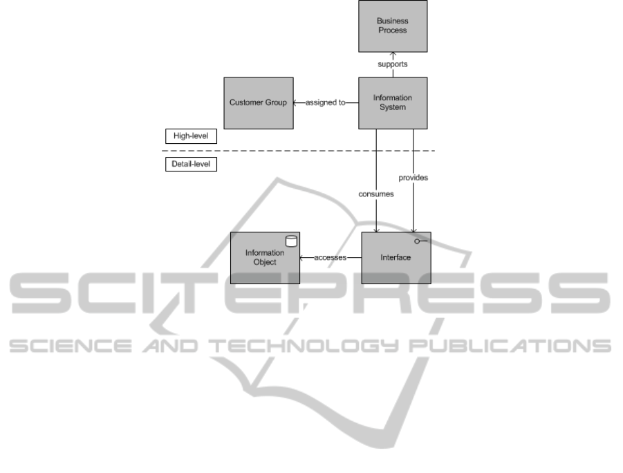
Figure 1: Information Model distinguishing High-level and Detail-level.
(class) supports (object property) a Business Process
(class). Cardinalities of object properties are not rep-
resented in Figure 1 but all object properties are one
to many, as e.g. an Information System may sup-
port several business processes or may be assigned
to several customer groups. Data properties, i.e. at-
tributes of classes, were not modelled. The informa-
tion model in Figure 1 can represent the business sup-
port information systems and their assignment to cus-
tomer groups in a simple way. However, there may
be situations where the presented information model
could not reconstruct the business support of infor-
mation systems in an appropriate way. In this case it
is necessary to introduce a ‘BusinessSupport’ class,
which is connected with exactly one process and one
customer group (c.f. Buckl et al., 2009). For our ex-
amples we use the simpler version, as it can be used
for all examples that have to be modelled. However,
the approach presented in this paper is not limited to
the simpler version of the information model but is
easier to describe and understand.
4.2 Modelling Current and Target State
Figure 2 shows an excerpt of a process support map
representing a current and target state of an enterprise
architecture model. The underlying information in the
ontology for this information is modelled as follows
exemplified with the information system Elcaro CRM
in the current state. Elcaro CRM supports the busi-
ness process Sales Governance and is assigned to En-
terprise and Institutional Clients. In the target state
Elcaro CRM supports the business process Customer
Management and is assigned to Private, Enterprise
and Institutional Clients. The instances of classes,
of the current as well as the target state are based on
the same classes. First, a current state was modelled
as shown in (Hanschke, 2012, Figure C.2, p.7). Af-
terwards, a target state was modelled by reusing the
model of the current state and changing it to the de-
sired target state (Hanschke, 2012, Figure C.3, p.7).
Every information system that is modelled supports
at least one business process and is at least assigned
to one customer group.
Results of the Modelling
The result of this phase are two ontologies:
currentState = modelled ontology of the current state
of the enterprise architecture
targetState = modelled ontology of the target state of
the enterprise architecture
A copy of the current state needs to be kept in order
to be able to perform the gap analysis later on.
4.3 Performing a Gap Analysis
The gap analysis was performed using OWLDiff
(Kremen et al., 2011). It is a plugin for Prot
´
eg
´
e, which
can be used to compare and merge OWL ontologies.
We used OWLDiff to compare the modelled current
and target state. Two result sets onlyCurrentState and
onlyTargetState, which are relevant for the proposed
approach, are produced by OWLDiff. In order to be
able to compare the two ontologies it is necessary that
current and target state have the same namespace.
ICEIS2013-15thInternationalConferenceonEnterpriseInformationSystems
214
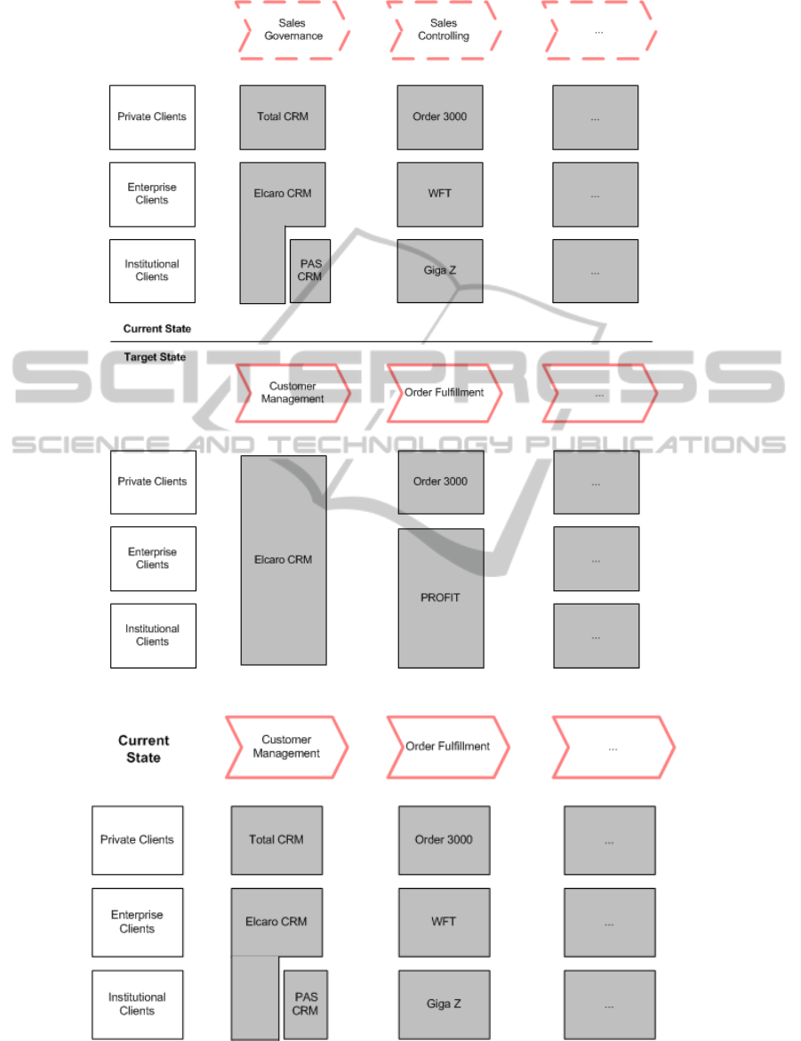
Figure 2: Excerpt of a Process Support Map for Current and Target State.
Figure 3: Current State after Localization.
GapAnalysisinEnterpriseArchitectureusingSemanticWebTechnologies
215

Results of the Gap Analysis
onlyCurrentState is the set of classes, object proper-
ties, data properties and instances that only exist in
the model of the current state.
onlyCurrentState = {x | ∀x : x ∈ currentState
∧x /∈ targetState}
In contrast, onlyTargetState is the set of classes, ob-
ject properties, data properties and assertions that
only exist in the target state.
onlyTargetState = {x | ∀x : x /∈ currentState
∧x ∈ targetState}
Both sets consist only of the changed instances and
their changed object properties, as data properties
were not modelled and the information model, in Fig-
ure 1, remained unchanged between the current and
target state. In accordance to Figure 2 this means
that the information system PAS CRM is part of the
set onlyCurrentState, as it is not present in the target
state. The assertion Elcaro CRM assigned to Private
Clients belongs to the set onlyTargetState as this rela-
tionship is only present in the target state. Order 3000
and its object property assertions are neither part of
onlyCurrentState nor onlyTargetState. The business
processes between the current and target state also
changes and thus Sales Governance and Sales Con-
trolling are also part of onlyCurrentState. Further-
more, the business processes Customer Management
and Order Fulfillment belong to onlyTargetState. The
proposed solution in Hanschke (2009) is to create a
common localization, i.e. the same customer groups
and business processes as in the target state, for the
information systems of the current state. This change
was modelled manually as proposed by Hanschke.
Figure 3 shows the information systems of the cur-
rent state with the same localization as for the infor-
mation systems in the target state. The gap analy-
sis can be performed again and the changed business
processes are no longer part of onlyCurrentState and
onlyTargetState.
4.4 Setting the Successor Relationships
for Information Systems
In order to be able to set the successor relationships
for information systems the ontology of the target
state is transferred to a different namespace than the
current state and a transformation ontology is cre-
ated that contains the information about successor re-
lationships (Aier and Gleichauf, 2010b). Changing
the namespace of an OWL ontology can be done in
Prot
´
eg
´
e. The set of information systems, business
processes and customer groups are defined as follows:
businessProcess = {x | ∀x : x isA Business Process}
informationSystem =
{x | ∀x : x isA Information System}
customerGroup = {x | ∀x : x isA Customer Group}
The successor relationship for information systems is
defined as:
successor (x, y) ≡ x,y ∈ informationSystem
∧x ∈ targetState ∧y ∈ currentState
∧∃b : b ∈ businessProcess ∧ x supports b
∧y supports b ∧ ∃c : c ∈ customerGroup
∧x assigned to c ∧ y assigned to c}
As the target and current state do not have the same
namespace for setting the successor relationships it is
necessary to include information which business pro-
cess in the current state is the same as in the target
state. This was modelled manually in the Prot
´
eg
´
e tool.
An alternative is to relate the information systems of
the target state to the customer groups and business
processes of the current state. We did not use this
alternative as we used a copy and transferred it to a
different namespace. However, we recommend to in-
clude this information as otherwise, the queries on the
models have to include the information which busi-
ness process of the current state is the same business
process in the target state. An automated addition of
this information can be implemented, as the results
from the gap analysis show that there are no changes
in business processes and customer groups.
Setting the successor relationship can be done
with SPARQL queries using the CONTSRUCT com-
mand, which allows to use SPARQL as a simple rule
language. This task cannot be performed in Prot
´
eg
´
e.
In our case the rule is that if an information system
supports a certain business process and is assigned
to a certain customer group the element in the target
state is a successor of the information system that sup-
ports the same business process and is assigned to the
same customer group.
We modelled the information of the same individ-
uals manually. For each information system in the
current state check which information system with the
same localization is in the target state and create a suc-
cessor relationship. With the successor relationships
at hand it is possible to identify the dependency type
for information systems which can be divided into
noSuccessor, noPredecessor, oneToOne, oneToMany,
manyToOne, and manyToMany. All information sys-
tems in onlyCurrentState that do not have a succes-
sor belong to the set noSuccessor whereas all infor-
mation systems that belong to onlyTargetState and do
not have an incoming successor relationship belong
to the set noPredecessor. The set oneToOne consists
of the pairs of information systems that have exactly
one successor and this successor has only one pre-
decessor. oneToMany is the set of information sys-
tems that have several successors in the target state
ICEIS2013-15thInternationalConferenceonEnterpriseInformationSystems
216

whereas the set manyToOne is the set of information
systems which have the same successor in the target
state. manyToMany is the set of information systems
which have several predecessors and successors. To
which set an information system belongs to can also
be determined by SPARQL queries.
A successor relationship is part of exactly one of
the above sets. Please note that within the six differ-
ent sets disjoint subsets exist. From Figure 2 two dis-
joint subsets of the manyToOne set could be derived.
The first subset consisting of Total CRM (successor),
PAS CRM (successor) and Elcaro CRM (predeces-
sor) whereas the other consists of Giga Z (successor),
WFT (successor) and PROFIT (predecessor). For the
noSuccessor and noPredecessor set each information
system represents a disjoint subset. In order to make
suggestions the model of the current state is now de-
tailed considering interfaces and information objects
(c.f. Figure 1). With the detailed information of the
current state and the successor relationships at hand
it is possible to generate suggestions how a detailed
target state could look like.
4.5 Creating Suggestions for a Detailed
Target State
Depending on the successor set an information system
belongs to different suggestions are made and a user
can follow or overrule them. By following a sugges-
tion or not the target is stepwise getting more detailed,
as all sets of successor relationships are getting pro-
cessed. The result is a detailed target state. At first
all provided interfaces are transferred to the detailed
target state. Then the consumes dependencies can be
added to the detailed target state.
4.5.1 Suggestions for Provided Interfaces
1. noSuccessor set: for each provided interface in
the current state check if it is consumed by an in-
formation system that is part of the target state or
the consuming information system has a succes-
sor relationship.
(a) If there are any information systems it is nec-
essary to check if they still can work properly
without consuming the interface.
(b) Otherwise, no information from the current
state is added to the target state.
2. noPredecessor set: it is not possible to suggest a
detail for the target state as there exists no detail in
the current state. A manual addition of provided
interfaces and their information objects in the tar-
get state is necessary.
3. oneToMany set:
(a) If the predecessor is part of onlyCurrentState
all provided interfaces of the predecessor, in-
cluding their information objects, are suggested
to be provided by one of the successor informa-
tion systems.
(b) Otherwise, all provided interfaces and informa-
tion objects of the predecessor are suggested to
be provided by one of the successor informa-
tion systems or the remaining part of the prede-
cessor in the target state.
4. manyToOne set:
(a) If the successor is part of onlyTargetState it is
suggested to provide each interface of its suc-
cessors, but only one per information object.
(b) Otherwise, it is suggested that the successor
provides the interfaces already provided in the
current state, i. e. by itself, and provide all in-
terfaces of the other predecessors, but only one
per information object.
5. manyToMany set: All provided interfaces are sug-
gested to be provided by one of the successors. If
more than one predecessor provides an interface
with the same information object the suggestion
is to provide only one interface in the target state
with such an information object. Further sugges-
tions were not identified as this type represents a
complex type of restructuring. Nevertheless, the
user should be supported with information about
information systems changing business support
and assigned customer groups. Furthermore, in-
formation which information systems belong to
onlyCurrentState and onlyTargetState needs to be
presented to the user.
6. oneToOne set: all interfaces, including their infor-
mation objects, provided by the predecessor are
suggested to be provided by the successor.
7. Furthermore, the user can model additional pro-
vided interfaces or let suggested interfaces be pro-
vided by an information system that is not a suc-
cessor of the information system that provided it
in the current state.
8. For each interface information is stored if it is the
successor of one or more interfaces in the current
state. This is necessary to allow a sound migration
planning (Aier and Gleichauf, 2010a).
As a result all provided interfaces have been mod-
elled in the target state including their information
objects. Furthermore, the information about succes-
sor relationships of the interfaces is available.
GapAnalysisinEnterpriseArchitectureusingSemanticWebTechnologies
217
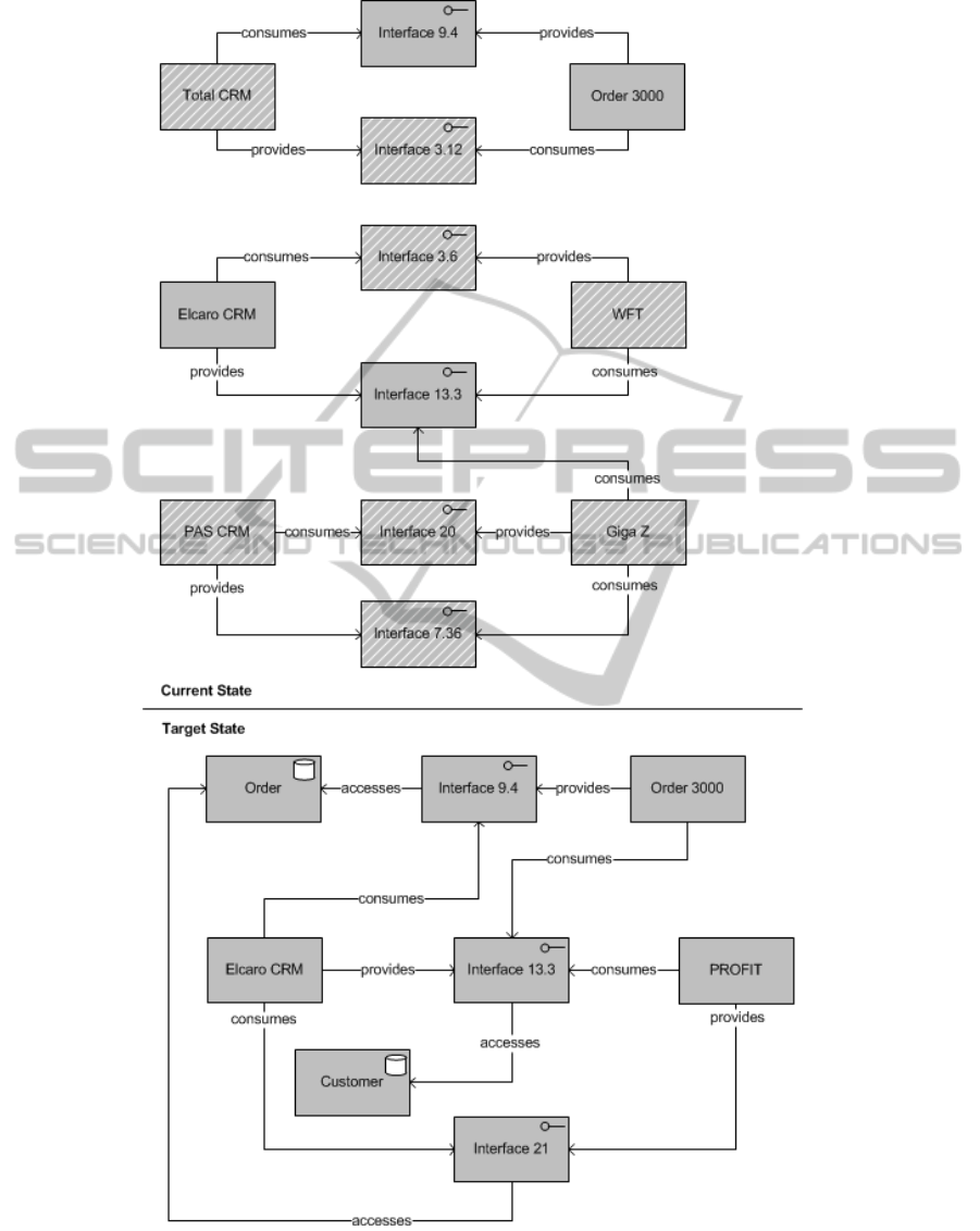
Figure 4: Excerpt of detailed Current and an exemplary Target State.
ICEIS2013-15thInternationalConferenceonEnterpriseInformationSystems
218

4.5.2 Suggestions for Consumed Interfaces
1. manyToMany set: all consumed interfaces of pre-
decessors are suggested to be consumed by at
least one successor. The user can choose if more
than one successor consumes the interface of a
predecessor.
2. oneToOne set: all interfaces consumed by the pre-
decessor are suggested to be consumed by the suc-
cessor.
3. manyToOne set: consumed interfaces of the pre-
decessors are suggested to be also consumed in
the target state.
4. oneToMany set:
(a) If the predecessor is part of onlyCurrentState
all consumed interfaces of the predecessor are
suggested to be consumed by one of the succes-
sor information systems.
(b) Otherwise, all consumed interfaces of the pre-
decessor are suggested to be consumed by one
of the successor information systems or the re-
maining part of the predecessor in the target
state.
5. noPredecessor set: which interfaces are con-
sumed by the information system need to be mod-
elled manually as no information from the current
state is available.
6. noSuccessor set: as the information system does
not exist in the target state no information about
consumed interfaces needs to be added to the tar-
get state.
7. Furthermore, the user can model additionally con-
sumed interfaces for every information system.
4.5.3 Results of the Guided Refinement
The result is a detailed target state including provided
and consumed interfaces with related information ob-
jects. Figure 4 shows an excerpt of a detailed current
and target state. The dashed boxes in the current state
indicate that the information systems belong to the
set onlyCurrentState and their provided interfaces are
suggested to be removed. Consistency checks can be
performed on the target state with SPARQL queries to
check whether interfaces exist which are provided but
no longer consumed by any information system. Af-
terwards, the namespace of the modelled detailed tar-
get state is changed to the namespace of the detailed
current state and the gap analysis can be performed
again. The user gets the detailed gaps between cur-
rent and target state.
With the results of the gap analysis and a detailed
current state it is possible to assist a user in mod-
elling a detailed target state by making suggestions
how to detail it based on the current state. The variety
of suggestions that can be provided is limited to the
information model. For example, technical informa-
tion about the interfaces can be added to allow more
sophisticated suggestions, like to prefer web service
technology for interfaces of information systems that
have to be build. Furthermore, the presented approach
should be evaluated in a real world setting with en-
terprises that use business support maps for planning
purposes. The creation of the OWL ontologies and
the SPARQL queries is also a task that needs expert
knowledge of semantic web technologies. Neverthe-
less, the proposed approach shows the ability of se-
mantic web technologies to assist in the planning pro-
cess without being limited to a certain methodology
or information model regarding the gap analysis. It
was also presented how the creation of successor re-
lationships between information systems of the cur-
rent and target state can be added automatically, us-
ing business support maps. Another advantage of the
proposed solution is the possibility to suggest solu-
tions for the target state only having defined a high
level target state.
5 SUMMARY
It was shown that semantic web technologies are ca-
pable to perform the gap analysis on a current and
target state on a high level as well as on a detail
level. Furthermore, the approach proposed how sug-
gestions for a user can be generated from the cur-
rent state to assist in the modelling of a detailed tar-
get state in detail. Metrics were not taken into ac-
count in the proposed approach. The further elab-
oration of metrics and their relation to the informa-
tion model needs to be considered in order to allow
a quantitative analysis of the current and target state.
Furthermore, Prot
´
eg
´
e requires knowledge of seman-
tic web technologies and is not ready to use for en-
terprise architects. Expert knowledge is necessary for
the OWL ontology creation, maintenance as well as
for the SPARQL queries. To implement the presented
approach in an EA tool, which is ready for production,
is also accompanied with an effort. Nevertheless, the
semantic web technologies offer the capability to per-
form the gap analysis and can be leveraged for plan-
ning support. Future work should also address the ca-
pability of semantic web technologies for automated
documentation of EA models.
GapAnalysisinEnterpriseArchitectureusingSemanticWebTechnologies
219

REFERENCES
Aier, S. and Gleichauf, B. (2010a). Application of enter-
prise models for enginnering enterprise transforma-
tion. Enterprise Modelling and Information Systems
Architectures, 5(1):56–72.
Aier, S. and Gleichauf, B. (2010b). Towards a systematic
approach for capturing dynamic transformation in en-
terprise models. In Sprague, R. H., editor, Proceed-
ings of the 43rd Annual Hawaii International Confer-
ence on System Sciences. IEEE Computer Society.
Bechhofer, S., van Harmelen, F., Hendler, J., Horrocks,
I., McGuiness, D., Patel-Schneider, P. F., and Stein,
L. A. (2004). OWL Web Ontology Language Refer-
ence. World Wide Web Consortium. Retrived Novem-
ber 5, 2012, from http://www.w3.org/TR/owl-ref/.
Buckl, S., Ernst, A. M., Matthes, F., and Schweda, C. M.
(2009). An information model capturing the managed
evolution of application landscapes. Journal of Enter-
prise Architecture, 5(1):12–26.
Buckl, S. and Schweda, C. M. (2011). On the State-of-
the-Art in Enterprise Architecture Management Lit-
erature. Technical Report, Technische Universit
¨
at
M
¨
unchen, Chair for Software Engineering of Business
Information Systems.
Deming, W. E. (1994). Out of the crisis: Quality, produc-
tivity and competitive position. Cambridge University
Press, Cambridge, 19 edition.
Engels, G., Hess, A., Humm, B., Juwig, O., Lohmann,
M., and Richter, J.-P. (2008). Quasar Enterprise:
Anwendungslandschaften serviceorientiert gestalten.
Dpunkt-Verlag, Heidelberg, 1 edition.
Grimm, S., Watzke, M., Hubauer, T., and Cescolini, F.
(2012). Embedded el + reasoning on programmable
logic controllers. In Hutchison, D., Kanade, T., Kit-
tler, J., Kleinberg, J. M., Mattern, F., Mitchell, J. C.,
Naor, M., Nierstrasz, O., Pandu Rangan, C., Stef-
fen, B., Sudan, M., Terzopoulos, D., Tygar, D., Vardi,
M. Y., Weikum, G., Cudr
´
e-Mauroux, P., Heflin, J.,
Sirin, E., Tudorache, T., Euzenat, J., Hauswirth, M.,
Parreira, J. X., Hendler, J., Schreiber, G., Bernstein,
A., and Blomqvist, E., editors, The Semantic Web
– ISWC 2012, Lecture Notes in Computer Science,
pages 66–81. Springer Berlin Heidelberg, Berlin and
Heidelberg.
Gringel, P. and Postina, M. (2010). I-pattern for gap
analysis. In Engels, G., Luckey, M., Pretschner,
A., and Reussner, R., editors, Software engineering
2010, Lecture Notes in Informatics, pages 281–292.
Gesellschaft f
¨
ur Informatik, Bonn.
Hanschke, I. (2009). Strategisches Management der IT-
Landschaft: Ein praktischer Leitfaden f
¨
ur das Enter-
prise Architecture Management. Hanser, M
¨
unchen, 1.
edition.
Hanschke, I. (2012). C planungs-muster: Download-
anhang zum buch strategisches management der it-
landschaft. Retrieved December 5, 2012, from http://
files.hanser.de/hanser/docs/20100621 21621165557-
63 HanschkeDownloadAnh%C3%A4nge final.zip.
Kremen, P., Smid, M., and Kouba, Z. (2011). Owldiff: A
practical tool for comparison and merge of owl ontolo-
gies. In 22nd International Workshop on Database
and Expert Systems Applications, pages 229–233.
IEEE Computer Society.
Lautenbacher, F. (2010). Semantic business process mod-
eling: Principles, design support and realization.
Shaker, Aachen.
Manola, F., Miller, E., and McBride, B. (2004). RDF
Primer. Retrived November 5, 2012, from http://
www.w3.org/TR/rdf-primer/.
Niemann, K. D. (2006). From enterprise architecture to
IT governance: Elements of effective IT management.
Vieweg, Wiesbaden.
Postina, M., Sechyn, I., and Steffens, U. (2009). Gap
analysis of application landscapes. In 2009 13th
Enterprise Distributed Object Computing Conference
Workshops, pages 274–281. IEEE Computer Society.
Prud’hommeaux, E. and Seaborne, A. (2008). SPARQL
Query Language for RDF. Retrived Novem-
ber 5, 2012, from http://www.w3.org/TR/2008/
REC-rdf-sparql-query-20080115/.
Pulkkinen, M. (2006). Systemic management of archi-
tectural decisions in enterprise architecture planning.
four dimensions and three abstraction levels. In Pro-
ceedings of the 39th Annual Hawaii International
Conference on System Sciences (HICSS’06), page
179a. IEEE Computer Society.
Pulkkinen, M. and Hirvonen, A. (2005). Ea planning, de-
velopment and management process for agile enter-
prise development. In Proceedings of the 38th Annual
Hawaii International Conference on System Sciences,
page 223c. IEEE Computer Society.
Shadbolt, N., Berners-Lee, T., and Hall, W. (2006). The
semantic web revisited. IEEE Intelligent Systems,
21(3):96–101.
Winter, R. and Fischer, R. (2006). Essential layers, artifacts,
and dependencies of enterprise architecture. In 2006
10th IEEE International Enterprise Distributed Ob-
ject Computing Conference Workshops (EDOCW’06),
page 30. IEEE Computer Society.
ICEIS2013-15thInternationalConferenceonEnterpriseInformationSystems
220
