
P-UML
A Pattern Design Language with a Formal Semantics
Nadia Bouassida, Hanêne Ben-Abdallah and Moez Ali
Mir@cl Laboratory, University of Sfax, Sfax, Tunisia
Keywords: Design Patterns Language, Formal Specification, Z Formal Language, UML.
Abstract: This paper presents and fine-tunes the P-UML design language which is a UML profile that better
represents the design patterns and guides their instantiation. Then, it focuses on the definition of the formal
semantics of this language in Z. The formal semantics allows a designer to prove the syntactic well-
formedness of a P-UML design. In addition, it allows the verification of a design pattern’s instantiation
thanks to the theorem prover Z/EVES.
1 INTRODUCTION
Design patterns (Gamma et al., 1995) offer solutions
that can be instantiated and composed to produce
software faster and with a good quality. When
presented in UML, a design pattern is a set of classes
with their relationships and their behaviour,
designed to solve a recurring problem. However,
design patterns are in some cases fairly difficult to
understand and reuse especially in complex systems.
These difficulties can be alleviated through a design
language that is expressive, that guides the user in
distinguishing among the variable and fixed parts of
the pattern, and that ensures the correct reuse of the
design patterns.
Numerous UML-based design languages for
patterns have been proposed cf. (Fontoura et al.,
2001), (Dong, 2002), (Dong et al., 2007), (Sanada
and Adams, 2002); (Arnaud et al., 2007). These
languages extend UML in order to support patterns’
specific concepts and to trace their elements when
reused. The fact that these languages are based on
UML increases their potential acceptance by
designers. However, none of these languages relies
on a formal, precise semantics that reinforces the
clarity of the language and provides for the
verification of pattern reuse.
On the other hand, several researchers have
proposed formalizations of patterns. These
propositions formalize either the structural (cf.,
(Taibi T. and Taibi F., 2006), (Kim and Carrington,
2006), (Blazy et al., 2006)) or the behavioural (Dey
and Bhattcharya, 2010) aspect of patterns. In
addition, some of these works rely on the definition
of a new specification language specific for reuse
(cf., (Eden et al., 1998), (Taibi T. and Taibi F.,
2006), (Dey and Bhattcharya, 2010)), while others
use formal languages and methods such as B, Z and
Object-Z (cf., (Blazy et al., 2002), (Kim and
Carrington, 2004)). Furthermore, these works focus
essentially on the formalization of the specific
concepts of patterns, without considering their
“informal/graphical” representation. We believe that
a design language for patterns should: represent
visually, clearly and intuitively patterns; formalize
the specificities of patterns; and provide for the
validation of pattern reuse.
In this paper, we present a formal semantics for
our UML-based language, P-UML (Bouassida et al.,
2006). The pattern design language P-UML with its
precise description facilitates a rigorous reasoning
on patterns and their reuse. It distinguishes visually
among the roles played by the elements of a pattern
and it shows the variability, while guiding potential
reuses of the pattern. Moreover, P-UML
distinguishes hook and template methods from other
methods in a pattern: template methods define
abstract and generic behaviour, while hook methods
provide their implementation (Pree, 1994). The
formal semantics of P-UML is defined in the Z
notation. It facilitates the unambiguous
understanding of a pattern and ensures correct reuse
through the theorem prover Z/EVES.
In the remainder of this paper, we first overview
UML-based notations for design patterns. Secondly,
197
Bouassida N., Ben-Abdallah H. and Ali M..
P-UML - A Pattern Design Language with a Formal Semantics.
DOI: 10.5220/0004440601970205
In Proceedings of the 15th International Conference on Enterprise Information Systems (ICEIS-2013), pages 197-205
ISBN: 978-989-8565-60-0
Copyright
c
2013 SCITEPRESS (Science and Technology Publications, Lda.)

we present briefly the P-UML design language.
Then, we present its well-formedness rules. Finally
we define the P-UML formal semantics by
translating its meta-model to a Z specification.
2 RELATED WORKS
2.1 Pattern Representation Languages
Fontoura et al., (Fontoura et al., 2001) proposed a
UML-based notation whose aim is to facilitate
pattern instantiation. The notation is composed of an
extended class diagram and an adapted activity
diagram (called “instantiation diagram”). The
extended class diagram is enriched with the tagged
values and stereotypes to show the variable parts of
a pattern (called hot-spots). One limit of this
notation is its lack of support for patterns
traceability; it does not keep track of the
correspondence between the elements of a pattern
and the application instantiating it. In addition, it
does not express how to compose patterns
The UML profile of Sanada (Sanada and Adams,
2002) aims to be comprehensive and well-defined. It
defines four stereotypes for design patterns and three
tags. It has the advantage of showing the pattern
participant roles. However, it lacks concepts to
identify the roles played by reused methods. Similar
to the UML profile of Fontoura et al., this notation
also does not facilitate patterns composition.
The notation proposed by Dong et al. (Dong,
2002) (Dong et al., 2007) focuses on design pattern
composition. It defines new tagged values that are
used to hold the pattern name, and the role names of
the classes, the attributes and the operations in the
pattern. Overall, this notation represents the
structure, participant roles and collaborations in a
pattern. However, it focuses more on pattern
composition than on pattern instantiation in a
particular application. For instance, it does not
visually distinguish between the hook and template
methods in a pattern.
The profile proposed by Arnaud et al. (Arnaud et
al., 2007) covers three views: functional, dynamic
and static. The functional view is materialized by a
use case diagram. This diagram begins the
instantiation process and any designer reusing a
pattern has to select a functionality variant from the
use case diagram. The dynamic view is modelled by
the sequence diagram as defined in UML 2.0. The
static view, modelled by a class diagram, is based on
the use of packages. In fact, design patterns are
presented with very elementary separated packages
which contain one or two classes. Each package is
relative to one use case. This may complicate the
diagram and makes its comprehension difficult.
Moreover, the class diagram proposed by Arnaud et
al. does not show the pattern participant roles, nor
does it express hook and template methods.
In summary, none of the proposed languages
shows simultaneously the pattern participants, their
roles, the meta-patterns and the hot-spots. In
addition, none of them has a formal semantics
making the design language clear and non
ambiguous.
2.2 Design Pattern Formalizations
The formalization of design patterns has been treated
either by defining a new language or by translating
them to existing formal languages.
As an example of works that propose the
definition of a new specification language specific
for pattern reuse, we find Taibi (Taibi T. and Taibi
F., 2006) who proposes the formalization of patterns
using a Balanced Pattern Specification Language
(BPSL) that uses both First Order Logic (FOL) and
Temporal Logic of Actions (TLA) in order to
specify the structural as well as behavioural aspects
of patterns. Another example adopting this approach
is the work of Dey (Dey and Bhattcharya, 2010)
who proposes FSDP (Formal Specification of
Design Pattern). The FSDP language formalizes the
textual content of the UML class diagram. Thus, the
classes, methods and attributes are represented, and
the behaviour is represented through relationships,
association and cardinality of the participating
classes. This work combines the work of Taibi
(Taibi T. and Taibi F., 2006) and (Dong, 2002), thus
it formalizes the roles that pattern participants play
in a composition. This formal language represents
only the structure; however the interactions which
are modelled through the sequence diagram and
method calls are ignored.
On the other hand, other researchers used
existing formal languages and methods such as B
and Object-Z to specify patterns (cf., (Blazy et al.,
2002), (Kim and Carrington, 2006)). Among these
works, Kim et al., (Kim and Carrington, 2004)
formalizes patterns using Object-Z. For this, they
rely on the meta-model of patterns, expressed in
UML. Thus, each pattern is considered as a pattern
role model. In fact, the role describes the pattern
participants which could be: a class, an attribute, an
operation and a relationship between classes. Note
that, since the role meta-model is formalized in
Object-Z, then the consistency constraints which
ICEIS2013-15thInternationalConferenceonEnterpriseInformationSystems
198

must be respected are formalized.
This approach was improved in Kim et al. (Kim
and Carrington, 2006) where the authors were
interested in the validation of pattern reuse. For this
purpose, they transform, automatically, the role
meta-model defined in Object-Z to an Ecore model
and then implement it using the Eclipse Modeling
Framework (EMF). Thus, patterns are deployed in a
design model by developing a role binding model
that maps pattern entities to the design model
entities. When a pattern is reused in a design model,
the corresponding constraints must be preserved to
make the pattern deployment valid. These
constraints, defined using Object- Z, are
implemented as a plug-in for Eclipse.
Blazy et al. (Blazy et al., 2002) formalize design
patterns with the B method. Each pattern is specified
with a unique abstract machine that is proved with
the Atelier B. This work is extended in (Blazy et al.,
2006) where an approach for the specification of
instantiations and compositions of design patterns
with others is proposed. The instantiation
mechanism is implemented in B by the inclusion of
machines: the machine corresponding to the pattern
is included in the machine corresponding to the
instantiation of the pattern. The composition is
treated through three levels (juxtaposition,
composition with inter-pattern links and unification)
according to whether or not there exist links between
the composed patterns. In the three cases,
composition is achieved by the inclusion mechanism
of B: all the machines representing the composed
patterns are included in the machine representing the
composition, called the composition machine. One
of the limits of this approach is that a pattern is
specified by a single abstract machine. As a
consequence, one can find big and complicated
machines, which impede their comprehension.
Another limit is that the composition of several
instances of the same pattern was not treated by this
approach.
3 THE PATTERN DESIGN
LANGUAGE: P-UML
The design language P-UML extends UML to enrich
UML diagrams, in order to show pattern participant
roles (e.g., observer, subject) and participant
relationships. The extensions allow us to set apart
core pattern classes from concrete and application
classes. In addition, they identify the methods that
play important roles in the pattern. Moreover, they
put the attention on pattern hot-spots and variations
through the meta-patterns (e.g., hook and template
methods). Finally, they distinguish among the
elements belonging to different design patterns,
when they are combined in a design.
P-UML models a design through a class diagram
that describes the static architecture of a pattern
through the following extensions:
An ellipse in in the bottom of a class indicating the
pattern name and the role through which this class
participates in the pattern.
An association between ellipses joins the elements
of the same pattern to show the participants of a
pattern and their dependencies.
A dashed line joins a hook and a template method.
The classes of the pattern core are highlighted and
stereotyped “core”. Note that a core class is a class
essential for the pattern (the classes subject and
observer are core classes in the Observer pattern.
The other pattern classes which are concrete classes
are not highlighted and they are stereotyped
“concrete” (e.g., The ConcreteSubject and
ConcreteObserver classes in the Observer pattern)
On the other hand, all the application classes are
not stereotyped and thus they can be easily
distinguished from the others.
Each association which is fundamental in the
pattern is drawn with a highlight.
Each fundamental method is tagged with its role in
the pattern.
The tag virtual associated to a circle filled in gray
in front of a method name indicates that the method
code varies from one implementation to another.
The tag extensible inside a class indicates that the
class has an extensible interface, i.e., a reuse may
add attributes and/or methods.
The UML constraint incomplete on a generalization
relation indicates that the pattern provides only a
sample of subclasses and that the user may add
other subclasses to reuse it.
Besides the class diagram, P-UML also proposes an
extension of the UML sequence diagram to describe
possible interactions between various object
instances of the class diagram; the reader is referred
to (Bouassida et al., 2006) for more details.
3.1 P-UML Example
Figure 1 shows the class diagram of an application
(inspired from (Sanada and Adams, 2002)) to
manage courses in a university. This application,
modelled in P-UML through our editor P-UML Tool
(Bouassida et al., 2006), instantiates and It combines
the patterns Strategy and Composite. The classes
P-UML-APatternDesignLanguagewithaFormalSemantics
199
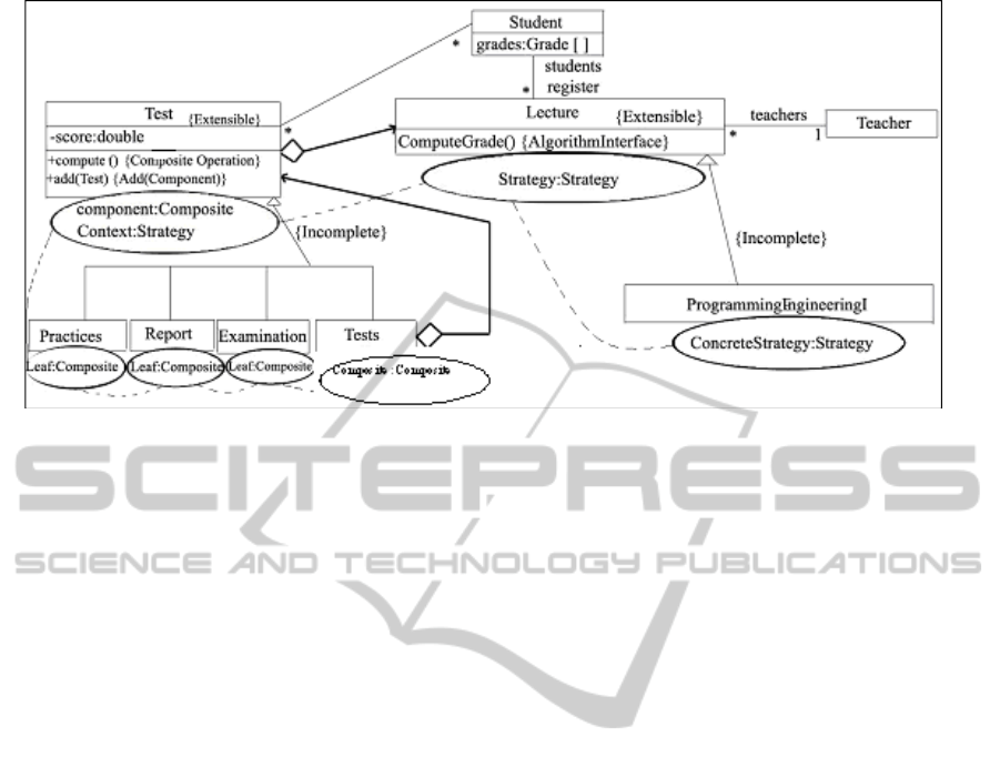
Design example represented with P-UML.
Test, Practices, Report, Examination, and Tests
participate in the Composite pattern. The objective is
to show that a Composite (the class Tests) delegates
its behaviour to its components (the class Test).
Besides playing the role of Component, the class
Test also plays the role of Context in the Strategy
pattern. The classes Practices, Report, Examination
are concrete classes since they play the role of a leaf.
In Figure 1, the roles played by each class are
represented in ellipses attached to the classes. On the
other hand, the pattern participants are linked with
the dashed lines. Note also that the roles played by
each method, which is essential to the pattern are
shown in Figure 1. For example, the method
Add(Test) plays the role of the Add() method; that
is, it adds components to the composite class.
3.2 P-UML Well-Formedness Rules
The P-UML well-formedness rules are syntactic
rules that guarantee the construction of a “correct”
design. These rules are necessary since using new
UML extensions may generate, in some cases,
inconsistencies (e.g., if a concrete class inherits a
core class, since concrete classes can be omitted in a
pattern instantiation).
Rule C1: The fundamental association, which is
highlighted, can join only core classes. Thus,
none of its association ends can be an application
class.
Rule C2: Each class stereotyped “core” must have a
corresponding object in the sequence diagram
also stereotyped “core”. Moreover, each class
stereotyped “concrete” must have a
corresponding object in a sequence diagram also
stereotyped “concrete”.
Rule C3: The fundamental method cannot be
omitted in a pattern instantiation.
Rule C4: The fundamental classes cannot be omitted
but the pattern concrete classes can be omitted.
Note, also, that their number could be extended.
Rule C5: The tag extensible exists only in pattern
classes (core or concrete) and it does not exist in
application classes.
4 P-UML FORMAL SEMANTICS
P-UMLwas initially proposed in (Bouassida et al.,
2006) as a graphical and semi-formal language. It
needed a formal semantics providing for a means to
“reason” about a P-UML specification and to verify
several properties like the correct instantiation of a
pattern.
In order to specify the semantics and syntax of P-
UML, we used the Z language (Meisels, 2004). The
choice of Z is motivated by the intuitive notation of
Z, its expressive power which covers all elements in
P-UML, its maturity as a formal notation, and the
availability of its theorem prover Z-EVES (Meisels,
2004).
To formalize the semantics of P-UML, we first
define a set Name as the domain of the names of all
classes, attributes, operations, parameters and
associations: [Name]. In addition, we define the
visibility of a P-UML attribute (private, public,
protected) through the following type:
Visibilitykind ::= private | public | protected.
A P-UML type has a name and a finite set of
attributes and operations.
PUMLType
ICEIS2013-15thInternationalConferenceonEnterpriseInformationSystems
200

name:Name
attributes:PUMLAttribute
operations:PUMLOperation
PUMLAttribute and PUMLOperation represent,
respectively, attributes and operations of a P-UML class.
Each attribute PUMLAttribute is described with the
following schema:
PUMLAttribute
name: Name
type: Classifier
visibility: VisibilityKind
The PUMLOperation is described by the following
schema:
PUMLOperation
name: Name
parameters: seq PUMLParameter
visibility: VisibilityKind
isAbstract: Boolean
PatInstance: PatName
PatRoleOp: RoleOp
TemplateOp: Boolean
HookOp: Boolean
VirtualOp: Boolean
FundamentalOp: Boolean
p1, p2: ran parameters
p1.name=p2.namep1=p2
This pattern is composed of the following Boolean
attributes: TemplateOp, HookOp, FundamentalOp.
In addition, it contains PatRoleOp to specify the role
played by the fundamental operation in the pattern
instance PatInstance. This latter is drawn from the
PatName free type: listing all design patterns:
PatName ::NONE Composite
Observer
AbstractFactory Builder ...
and the PatRoleOp is drawn from the RoleOp free
type listing all pattern elements’ roles:
RoleOp ::None Operation OperationImp
ADDComponent Construct BuildPart
Factorymethod Clone StaticInstance
...
4.1 P-UML Class Formalization
A P-UML pattern class is described by the following
PUMLClass schema in Z:
PUMLClass
name: Name
PatRoleCl: RoleClass
PatInstance: PatName
attributes: PUMLAttribute
operations: PUMLOperation
extensible: Boolean
isAbstract: Boolean
[C1] a1, a2: attributes a1.name = a2.name a1 = a2
[C2] op1, op2: operations op1 = op2
op1.name = op2.name
op1.visibility = op2.visibility
op1.parameters = op2.parameters
[C3] op: operations op.TemplateOp = True op.HookOp
= False
[C4] op: operations op.HookOp = True op.TemplateOp
= False
[C5] op: operations op.FundamentalOp = True
op.PatInstance = Composite
op.PatRoleOp = Operation op.PatRoleOp =
ADDComponent
op.PatInstance = Observer
op.PatRoleOp = Update op.PatRoleOp = Attach
op.PatRoleOp = Dettach op.PatRoleOp = GetState
op.PatRoleOp = SetState op.PatRoleOp = Notify
op.PatInstance = State
op.PatRoleOp = Request op.PatRoleOp = Handle
op.PatInstance = Adapter
op.PatRoleOp = Request op.PatRoleOp =
SpecificRequest
op.PatInstance = AbstractFactory
op.PatRoleOp = CreateProductA op.PatRoleOp =
CreateProductB
op.PatInstance = Builder
op.PatRoleOp = Construct op.PatRoleOp =
BuildPart
op.PatInstance = FactoryMethod op.PatRoleOp =
Factorymethod
op.PatInstance = Prototype
op.PatRoleOp = Clone op.PatRoleOp = Operation
op.PatInstance = Singleton
op.PatRoleOp = StaticInstance op.PatRoleOp =
SingletonOperation
op.PatInstance = Bridge
op.PatRoleOp = Operation op.PatRoleOp =
OperationImp
op.PatInstance = Decorator op.PatRoleOp = Operation
op.PatInstance = Proxy op.PatRoleOp = Request
op.PatInstance = Flyweight
op.PatRoleOp = Operation op.PatRoleOp =
GetFlyweight
op.PatInstance = ChainOfResponsibility op.PatRoleOp
= HandleRequest
op.PatInstance = Command
op.PatRoleOp = Execute op.PatRoleOp = Action
op.PatInstance = Interpreter op.PatRoleOp = Interpret
op.PatInstance = Iterator op.PatRoleOp =
CreateIterator
op.PatInstance = Mediator op.PatRoleOp = Operation
op.PatInstance = Memento
op.PatRoleOp = SetMemento
op.PatRoleOp =
CreateMemento
op.PatRoleOp = GetState op.PatRoleOp = SetState
op.PatInstance = Strategy
op.PatRoleOp = AlgorithmInterface
op.PatRoleOp = ContextInterface
op.PatInstance = TemplateMethod
P-UML-APatternDesignLanguagewithaFormalSemantics
201

op.PatRoleOp = Templatemethod op.PatRoleOp =
PrimitiveOperation
op.PatInstance = Facade op.PatRoleOp = Operation
op.PatInstance = Visitor
op.PatRoleOp = VisitConcreteElement
op.PatRoleOp = Accept op.PatRoleOp = Operation
[C6] op: operations op.FundamentalOp = False
op.PatRoleOp = None op.PatInstance = NONE
The PUML class has a name, attributes, operations,
and it must verify six invariants: [C1] and [C2]
ensure the attribute and method names in the same
class must be different; [C3] and [C4] ensure that we
can not have the same operation in a certain class
that takes the value Hook and Template at same
time; and [C5] and [C6] ensure that each basic
method in PUML is labeled with its role in the
pattern through the tag {Name-pattern: role-
method}". Note that, this is useful in patterns
instantiation. In fact, it specifies the name of the the
fundamental method of this pattern.
In addition, a P-UML class adds the following
attributes: extensible, PatRoleCl and PatInstance.
They indicate, respectively, the ability to add
attributes or methods to the class labeled
"extensible", the role played by the class
participating in the pattern and the pattern name.
The PatRoleCl is defined as a free type listing all
possible roles:
RoleClass ::Component composite Leaf
Abstractfactory ConcreteFactory1 ...
4.2 P-UML Relationships Formalization
In this section, we give some examples of UML
relationship formalization. Each PUMLAssociation
is described as follows:
PUMLAssociation
name: Name
e1, e2: AssociationEnd
AssocOblig: Boolean
[C7] ae1, ae2: AssociationEnd
ae1 = ae2
ae1.rolename = ae2.rolename
ae1.attachedClass = ae2.attachedClass
ae1.multiplicity = ae2.multiplicity
[C8] e1, e2: AssociationEnd
e1.associationTyp aggregation
composition
e2.associationTyp = none
This schema reuses the UMLAssociation schema as
defined in (Ali, 2010). It defines two invariants:
[C7] ensures the uniqueness of the names of the
association ends; and [C8] ensures, in the case of an
aggregation or a composition, that only one end of
the association has the type aggregation or
composition.
Each PUMLGenralization is described as follows:
PUMLGeneralization
super: PUMLClass
sub: PUMLClass
Incomplete: Boolean
super.attributes sub.attributes super.operations
sub.operations
4.3 PUML Class Diagram Formalization
A PUML class diagram is defined by the schema
PUMLClassDiagram. This schema states
respectively the set of classes and relationships (e.g.,
generalization, association, aggregation ...etc). This
schema is defined as follows:
PUMLClassDiagram
classes: PUMLClass
associations: PUMLAssociation
gen: PUMLGeneralization
[C9] c1, c2: classes c1.name = c2.name c1 = c2
[C10] a1, a2: classes a1.name = a2.name a1 =
a2
[C11] # classes 2 # associations 1
[C12] c: classes
c.PatInstance = Composite
c.PatRoleCl = composite
c.PatRoleCl = Leaf
c.PatRoleCl = Component
c.PatInstance = Strategy
c.PatRoleCl = strategy
c.PatRoleCl = Context
c.PatRoleCl = ConcreteStrategy1
c.PatInstance = Observer
c.PatRoleCl = observer
c.PatRoleCl = Subject
c.PatRoleCl = ConcreteObserver
c.PatRoleCl = ConcreteSubject ….
A PUML class diagram must satisfy four
constraints: [C9] and [C10] ensure uniqueness of
class names and associations (Ali, 2010); [C11]
ensures that a class diagram is composed of at least
two classes linked by an association (Ali, 2010); and
[C12] ensures that each class (participant) is labeled
with its role in the pattern :{Pattern-Name,
Participant- role}. This is useful when instantiating
patterns. It specifies the name of the pattern in which
the class participates and the role of this class.
ICEIS2013-15thInternationalConferenceonEnterpriseInformationSystems
202

5 VERIFICATION OF PATTERN
REUSE
The formal semantics of P-UML allows us to verify
several properties of an application instantiating
patterns. In order to illustrate the verification of
syntactic correctness of a pattern, we next present
the inscription system. In the verification process,
we used the Z/Eves theorem prover (Meisels, 2004).
We have translated the application of Figure 1 to
Z based on a set of instantiation axioms. Next, we
give our verification process composed of three
steps:
Step 1: Instantiation of P-UML elements:
To illustrate this step, we give an extract of the Z
axioms to instantiate a set of elements:
Score: PUMLAttribute
Score.name = score
Score.type = double
Score.visibility = private
Computer: PUMLOperation
Computer.name = computer
Computer.visibility = public
Computer.parameters =
Computer.isAbstract = False
Computer.PatInstance = Composite
Computer.PatRoleOp = Operation
Computer.TemplateOp = True
Computer.HookOp = False
Computer.VirtualOp = False
Computer.FundamentalOp = True
Add_Test: PUMLOperation
Add_Test.name = addTest
Add_Test.visibility = public
Add_Test.parameters =
Add_Test.isAbstract = False
Add_Test.PatInstance = Composite
Add_Test.PatRoleOp = ADDComponent
Add_Test.TemplateOp = True
Add_Test.HookOp = False
Add_Test.VirtualOp = False
Add_Test.FundamentalOp = True
test: PUMLClass
test.name = Test
test.PatRoleCl = Component Context
test.PatInstance = Composite Strategy
test.attributes = Score
test.operations = Computer Add_Test
test.isAbstract = False
test.extensible = True
computegrade: PUMLOperation
computegrade.name = ComputeGrade
computegrade.visibility = public
computegrade.parameters =
computegrade.isAbstract = True
computegrade.PatInstance = Strategy
computegrade.PatRoleOp = AlgorithmInterface
computegrade.TemplateOp = False
computegrade.HookOp = True
computegrade.VirtualOp = False
computegrade.FundamentalOp = True
lecture: PUMLClass
lecture.name = Lecture
lecture.PatRoleCl = strategy
lecture.PatInstance = Strategy
lecture.attributes =
lecture.operations = computegrade
lecture.isAbstract = True
lecture.extensible = True
programIng: PUMLClass
programIng.name = ProgrammingIngineeringI
programIng.PatRoleCl = ConcreteStrategy1
programIng.PatInstance = Strategy
programIng.attributes =
programIng.operations =
programIng.isAbstract = False
programIng.extensible = False
Due to space limitations, the classes Examination,
Report and Tests are not presented, they are similar
to the class Lecture.
g: PUMLGeneralization
g.super = test
g.sub = tests
g.Incomplete = True
a: PUMLAssociation
a.e1.attachedClass = test
a.e2.attachedClass = lecture
a.e1.multiplicity.upper = 0
a.e1.multiplicity.lower = 100
a.e2.multiplicity.upper = 1
a.e2.multiplicity.lower = 100
a.e1.associationTyp = aggregation
a.e2.associationTyp = none
Note that g1, g2, g3 are also generalizations defined
similarly to the generalization g. and a1 is an
association defined similarly to a.
Z/EVES generates automatically a set of axioms.
Each axiom has a goal and defines a theorem. For
example, the axiom $axiom185 defines a new
theorem:
theorem axiom axiom$185
Add_TestHookOp = False
P-UML-APatternDesignLanguagewithaFormalSemantics
203
Step 2: Instantiate the PUML class diagram (Figure
2):
In order to Instantiate the P-UML class diagram, we
use the following schema:
InitPUMLClassDiagram
PUMLClassDiagram
classes = test lecture programIng tests
examination report
associations = a a1
gen = g g1 g2 g3
Classes, associations and gen are the set of elements
of the P-UML example presented in section 3.2.
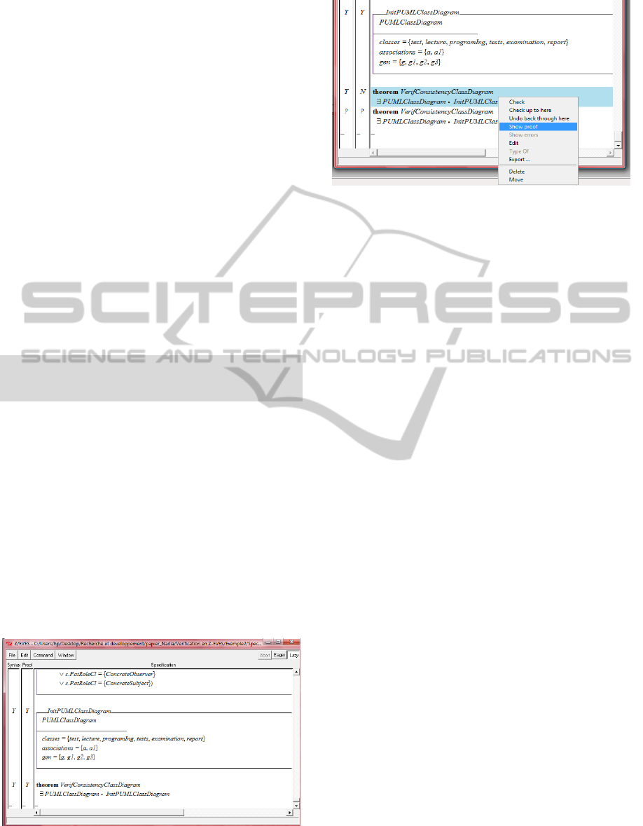
Step 3: Applying initial theorem:
After the instantiation of the P-UML class diagram,
we animate with Z/EVES the theorem
“VerifConsistency ClassDiagram”. It ensures that
the P-UML model is correct and that it is a valid
pattern instantiation.
theorem VerifConsistencyClassDiagram
PUMLClassDiagram
InitPUMLClassDiagram
Using Z/EVES, the proof of this theorem needs
the following commands:
1. Invoke
2. Use the set of generated axioms.
- Use $axiom164
- Use $axiom165
...
3. Rewrite
4. Prove by reduce
Figure 2 shows the theorem to be proven and Figure
3 shows it after the proof was successfully done,
which proves that our example of Figure 1 is a good
instantiation of design patterns.
Figure 1: Theorem before proof.
Figure 2: Theorem after the proof.
6 CONCLUSIONS
This paper overviewed proposed UML-based
notations for design patterns and it proposed a new
notation (P-UML) that distinguishes among the
different parts in the pattern structure. Then, it
defined the formal semantics of the P-UML class
diagram with the formal notation Z.
Our future work includes formalizing the
behaviour of P-UML through the specification of the
P-UML sequence diagram. In addition, we are
looking into testing the formalization of P-UML
through different examples.
REFERENCES
Arnaud N., Front A. and Rieu D., “Expression et usage de
la variabilité dans les patrons de conception”, Revue
des sciences et technologies de l'information, Vol.
12/4, pp. 21-24, 2007.
Ali. M., “Formal verification and validation of UML
models: Approaches and tools”. Editions
Universitaires Europeennes, 2010.
Blazy S., Gervais F., Laleau R., “Reuse of Specification
Patterns with the B Method” , 2006.
http://www.arxiv.org/abs/cs/0610097v1
Blazy, S., Gervais, F., Laleau, R.., “Un exemple de
réutilisation de patterns de spécification avec la
méthode B”. Technical report. 395, CEDRIC
Laboratory, Evry, France, 2002.
Bouassida N., Ben-Abdallah, Ben-Hamadou A.
“Extending UML to guide design pattern reuse”,
fourth ACS/IEEE International Conference on
Computer Systems and Applications, Dubai, 2006.
Dey S, Bhattcharya S., “Formal specification of structural
and behavioral aspects of design patterns”, Journal of
Object Technology, Volume 9, N°6 (November 2010),
pp. 99-126.
Dong J., “UML extensions for design pattern
compositions”, Journal of object technology, Vol. 1,
ICEIS2013-15thInternationalConferenceonEnterpriseInformationSystems
204

N° 5, pp 149-161, 2002.
Dong J., Yang S. and Zhang K., “Visualizing design
patterns in their applications and compositions”,
Proceedings of IEEE transactions on software
engineering, pp. 433-453, 2007.
Eden, A., Hirshfeld, Y., Yehudai, A., “LePUS - a
declarative pattern specification language”. Technical.
report. 326/98, Department of Computer Science, Tel
Aviv University, 1998.
Fontoura. M. F., W. Pree and B. Rumpe, “Extending UML
to improve the representation of design patterns”,
JOOP, Vol. 13, N°11, pp. 12-19, March , 2001.
Gamma E., R. Helm, R. Johnson and J. Vlissides (1995),
Design patterns: Elements of reusable Object
Oriented Software, Addisson-Wesley, Reading, MA.
Kim S. K. and Carrington D., “A tool for a formal pattern
modeling language”. 8
th
International Conference on
Formal Engineering Methods (ICFEM 2006), LNCS
4260, pp. 568-587, China, 2006.
Kim S. K. and Carrington D., “Using Integrated
Metamodeling to Define OO Design Patterns with
Object-Z and UML”. Proceedings of the 11
th
Asia
Pacific Software engineering Conference, 2004.
Marcano, R., Meyer, E., Levy, N., Souquieres, J.,
“Utilisation de patterns dans la construction de
spécifications en UML et B”. Proceeding
AFADL’2000, Technical report., LSR Laboratory,
Grenoble, France, January 26-28, 2000.
Pree W., “Meta-patterns: a means for capturing the
essentials of object-oriented designs”, Proceedings of
the 8
th
European Conference on Object Oriented
Programming, Bologna-Italy, 1994.
Sanada Y., Adams R. (2002) CO, “Representing Design
Patterns and Frameworks in UML-Towards a
Comprehensive Approach”, Journal of Object
Technology, Vol. 1, N°2, July-August.
Taibi T., Taibi F., “Formal specification of design
patterns and their instances”, Fourth ACS/IEEE
International Conference on Computer Systems and
Applications (AICCSA-06), March 8-11, Dubai, 2006.
Meisels I., Software Manual for Windows Z/EVES
Version 2.3. TR-97-5505-04h, ORA Canada, June
2004.
P-UML-APatternDesignLanguagewithaFormalSemantics
205
