
Change Management of BPM-based Software Applications
Mourad Bouneffa and Adeel Ahmad
Universit´e Lille Nord de France, Laboratoire d’Informatique Signal et Image de la Cˆote d’Opale,
50, rue Ferdinand Buisson, BP 719, 62228 Calais Cedex, France
Keywords:
BPM, Software Evolution, Change Impact Propagation, Graph Rewriting Rules, Process Change Management.
Abstract:
Business process models are decision making tools intended to describe operations, constraints, and poli-
cies of an organisation. In this paper, we present an approach to control the evolution of Business Process
Model (BPM) based software applications. We define a BPM change taxonomy and focus on the change af-
fecting the BPMs and its impact propagation, through traceability relationships, to the software applications
implementing them. From a formal point of view, our work consists of specifying a BPM meta-model using
a typed attributed graph and a BPM change operations taxonomy based on graph rewriting rules. The specifi-
cations are then implemented using an integrated software change management platform appearing as a set of
the Eclipse Workbench plug-ins.
1 INTRODUCTION
The communication means and interfaces between
human users and the automated information systems
are rapidly developing for the past decade. Thus,
the idea to automate most of the information system
processes, destined to managing an organization, is
far from being a utopia. It is therefore possible for
an external user of the organization to communicate
with the information system of such an organization
through various types of communication media and
interfaces such as voice systems, applications running
on smart-phones, etc. Moreover, these entry points
to information systems can be provided by the vari-
ous devices of operational systems to facilitate a co-
herent integration of the different organizational ac-
tors, management processes, and software applica-
tions supporting these processes.
This leads to the emergence of new software de-
velopment tools and approaches based on the Busi-
ness Process Model(BPM)(Weske, 2007; Weske,
2012) concept. In these approaches the BPMs
are specified by means of some standard nota-
tions like BPMN (Silver, 2009; Allweyer, 2010) and
XPDL (Van der Aalst, 2003; Haller et al., 2008).
The BPMs are then transformed into executable pro-
grams that are generally deployed as multi-tiered
distributed applications using platforms like J2EE,
.NET, etc. The executable programs are often built
as macro programs implementing the well known
concept of programming in the large(Emig et al.,
2005). These programs contain invocations of web
services(Gottschalk et al., 2002) provided by the var-
ious software applications which have been deployed
inside or sometimes outside the information system
boundaries. The Business Process Execution Lan-
guage(BPEL)(Juric, 2006) is one of the most known
programming in the large language.
In this paper, we precisely consider the study of
this new generation of applications. Our goal is to
demonstrate the feasibility of the implementation of a
process to control the change impact which may af-
fect these applications. For this purpose, we elaborate
a meta-model permitting to represent the most signif-
icant elements of a BPM. The major objective is to
formally construct a structure to express the several
BPM change operations.
The meta-model is formalized using typed and at-
tributed graphs. Our modelling choice of formally
specifying BPM allows to describe change operations
using graph rewriting or transformation rules. Such
rules can, indeed, permit a visual definition of the
effective change operations. These are adapted to
study the software artifact changes which are often
expressed by the graph change operations. A taxon-
omy is then elaborated to define the construction rules
and BPM transformations. The obtained specification
is aimed at defining a change impact not only on BPM
itself but also on concerned components of the BPM
based software applications. Our goal includes the
traceability between software applications, deploy-
ment platforms, software system actors and BPMs.
37
Bouneffa M. and Ahmad A..
Change Management of BPM-based Software Applications.
DOI: 10.5220/0004441400370045
In Proceedings of the 15th International Conference on Enterprise Information Systems (ICEIS-2013), pages 37-45
ISBN: 978-989-8565-60-0
Copyright
c
2013 SCITEPRESS (Science and Technology Publications, Lda.)

The main objectivebeing to control the change impact
propagation through all, or a specified part of such a
software system.
In Section 2 we present, the meta-model for the
BPM formalization and the notions relevant to BPM
and BPM-based software applications. In section 3,
we specify a taxonomy of BPM change operations
and we give the formalization of these operations by
the graph rewriting rules. The section 4 presents
the change impact analysis and propagation process
along with its formalization by the graph rewriting
rules. The section 5 shows the prototype implemen-
tation of our specifications in regard to the integrated
platform to control the software changes(M. O. et al.,
2010). The section 6, summarizes the contribution
by a conclusion with the different perspectives of this
work.
2 BPM FORMALIZATION AND
META-MODELING
Before explaining the formalization and meta-
modeling of BPM, we first explain the concept of
BPM and especially the life cycle of software appli-
cations based on the BPM. As shown in Fig. 1, the de-
velopment, deployment, and evolution of BPM based
software applications obey a life cycle. The phases
of BPM life cycle are described in the following sec-
tions:
Figure 1: The life cycle of BPM based applications.
2.1 The BPM Modeling
This phase involves BPM Modeling in terms of tasks
or activities which are necessary to implement the
process, the order of tasks accomplishment, the hu-
man actors involved in the performance of these tasks,
etc. In recent years, several models or notations have
been defined to model the BPM. At first, designing a
BPM is an activity within the scope of the informa-
tion system cartography. It was most often performed
as a part of BPR (Business Process Re-engineering)
projects (Lee et al., 2011). Thus, many models and
methods have been implemented such as the OS-
SAD method(Dumas et al., 1990), etc. Our present
work is particularly related to the BPM as a means
of specification, development, and deployment of au-
tomated processes. We selected the widely consid-
ered and used notations in this area, particularly the
BPMN(OMG, 2011). Fig. 2 shows an example of
such a process. In this figure, the process is a partial
description of the Sales Chain Management. We first
distinguish two important actors: the Client and the
Process Order. At the beginning, a start event repre-
sent the fact that Place Order is the first task. This
first task performed by the Client consists of the gen-
eration of an order that is sent as a message to the
Check Availability task, which is linked to a gateway
involving the Check Payment task. If the products are
available or the Cancel Order otherwise, etc. The pro-
cess ends by end events linked with Confirm Order
and Cancel Order tasks.
2.2 The Development and the
Deployment of the BPM
The development and the deployment of a BPM are
two separate activities that can be performed manu-
ally, automatically, or usually semi-automatically. In
principle, these activities can be considered as classi-
cal operations for code generation, where the BPM
plays the role of a detailed design and the code is
represented by an application, deployed most often
on a web platform. There exists also software tools
to automate the deployment of such applications al-
most transparently. Some of these tools are Bonita
1
,
Intalio
2
, BizAgi
3
and Barium Live!
4
, etc. In these
tools a web application is generated and is hosted
by a Java servlet engine or in the form of ASP.NET
pages, etc. Without going to the full automation and
complete transparent development and deployment of
BPM based applications, there are intermediate lan-
guages playing the role of orchestrators or macro pro-
grams involving software components already encap-
sulated by web services. BPEL is one of the main
languages of this type and appears like a sort of stan-
dard in the matter. In one perspectiveof Model Driven
Engineering(MDE)(Schmidt, 2006), BPMN can be
considered as a Platform Independent Model (PIM)
and BPEL as a Platform Specific Model(PSM) con-
sisting of implementing BPMN in an environment us-
1
Bonita Open Solution url: http://www.bonitasoft.com/
2
Intalio—BPMS : http://www.intalio.com/
3
Bizagi BPM Suite : http://www.bizagi.com/
4
Barium Live! : http://www.bariumlive.com/
ICEIS2013-15thInternationalConferenceonEnterpriseInformationSystems
38
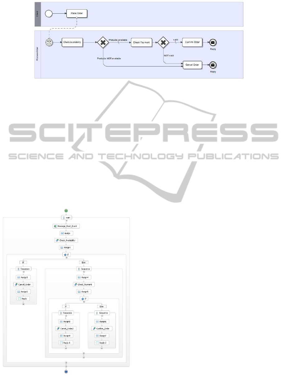
Figure 2: An example of Business Process Model Notation.
ing web services as a means of communication and
interoperability.
Fig. 3 shows an example of BPEL implementing
the BPM shown in Fig. 2. In this figure the BPEL is
a kind of web services orchestration. To do this, the
BPEL contains calls or invocations to web services
like Check Availability, Check Payment and Cancel
Order and flow management nodes like sequence for
a sequential execution of web services invocations or
If for conditional branches. It is useful to remark that
the programming in the large concepts are quite sim-
ilar to the programming in the small (DeRemer and
Kron, 1975) ones. For our example, the tasks or ac-
tivities of the BPMs are implemented by web service
calls while gateways are implemented by If nodes.
Figure 3: An example of Business Process Execution Lan-
guage.
2.3 The Execution and Monitoring of
the BPM
The execution of the application is generally assured
by a web platform which is usually on multi-tiered
architecture etc. The BPM execution provides gener-
ally some interesting data such as response time, re-
source consumption, etc. These data are necessary
for the purpose of analyzing the process quality. In-
deed, business managers define performance indica-
tors (Key Performance Indicator(Parmenter, 2007))
for each process, to measure the performance of ac-
tivities implemented by processes. Some of these in-
formations can be obtained by dynamic analysis by
means of program profiling techniques(Ahmad et al.,
2008b; Ahmad and Basson, 2009; Ahmad et al.,
2009). Other information are exclusively provided
by human experts and will be explicitly taken into
account by some organizational process. They are
generally the derived data from activities within the
framework of customer satisfaction, etc. In (Dadam
et al., 2007), the authors propose, during the execu-
tion of processes, to consider particularly the excep-
tions. In some other areas, such as medical processes,
it is not possible to foresee all possible cases and to
model them through the processes. Thus, the authors
in (Dadam et al., 2007) propose and implement an ex-
ception handler, able to propose an alternative imple-
mentation or implementations of processes on the fly.
A system of corporate knowledge about exceptions
can then eventually propose improvements to the ini-
tial process to take into account the various excep-
tions.
2.4 The BPM Improvement
The process improvement is a generic term that refers
primarily to the evolution of BPM processes. In real-
ity, the improvement is expected but what is actually
done, is an evolution of a process embodied by the
ChangeManagementofBPM-basedSoftwareApplications
39

change affecting the BPM processes. The goal is to
fix certain performance anomalies or simply to com-
plete the automation of processes, a part of which is
manual, etc. In the literature, the improvement is seen
only on the process side and it ignores the software
implementation problems. In our case, we consider
both aspects, analyzing in particular the BPM change
impacts on the software and vice versa.
2.5 A Meta-model of Graph-based BPM
We propose a meta-model to represent the concepts
involved in the definition of BPMs. This meta-model
has been formalized by a typed graph that we im-
plement particularly in the context of the AGG
5
.
The result of this modeling is shown schematically
in the Fig. 4. This figure represents the main con-
cepts emerging from the BPMN. The process concept
represents the processes that contain what is called
flow objects. These objects can be tasks or activi-
ties, sub-processes or macro-tasks, refined by the pro-
cesses, events or gateways. A process has an actor
which is called the owner which may be one user, or
more, who has defined the process and is authorized
to change this process. The process is implemented
by an application which is deployed and which can
host the execution of multiple instances or cases of
this process. Every instance involves actors that are
the users interacting with the various tasks performed
during the instance life cycle.
3 THE TAXONOMY OF CHANGE
OPERATIONS
In the development and the deployment of BPM-
oriented applications, the change seems inevitable. It
enrolls in fact, in the usual life cycle of this kind of ap-
plications. We define it as a taxonomy of change op-
erations that may affect one of the important compo-
nents of these applications to know the BPM. We con-
sider two kind of changes: the atomic change opera-
tions and composite or complex change operations.
3.1 The Atomic Change Operations
The formalization of a BPM as a typed attributed
graph allows us to compile a list of atomic change op-
erations. It is important to notify that, ”each change
operation corresponds to an insertion, deletion or
modification of a node or an edge of this graph”. We
thus obtain the following change operations:
5
http://user.cs.tu-berlin.de/ gragra/agg/
• Insert a process
• Delete a process
• Modify a process(name, description, etc.)
• Insert a new task
• Delete a task
• Modify a task
– Modify an attribute of the task(name, descrip-
tion, etc.)
– Modify the type of a task (automatic, manual,
etc.)
• Insert an event
• Delete an event
• Modify an event(start event to intermediate event,
etc.)
• Insert a gateway
• Delete a gateway
• Modify a gateway(condition of application: OR
to XOR, etc.)
• Insert an edge or link(between two flow objects)
• Delete an edge between two flow objects
• Et cetera.
Each defined atomic change operation is then for-
malized by graph rewriting rules. A graph rewriting
rule is in fact a production rule where the left and right
sides of the rule are graphs. In other words, a pro-
duction rule that transform a part of the graph which
match or corresponds to the left hand side (LHS) of
the production by another subgraph represented by
the right hand side(RHS) of the production. There
are also preconditions called negative or NAC, which
specify the need for non existence of certain sub-
graph for the rule to run.
Visually such a rule can be outlined as in the
Fig. 5. This figure depicts the partial creation or in-
sertion of a new task. It shows the three components
of a rule called InsertTask which represents the inser-
tion of a task in a process. The LHS of the rule states
that there must be a node in the graph of process type.
It would then match a process node of the graph with
that of the rule. This matching can be done manually
by the user or automatically by the graph rewriting
system following many methods that are out of the
scope of this paper. The RHS of the rule shows the
creation of a task called x connected to the process by
the relationship ”contains”. The NAC of the rule pro-
hibits the creation of a task named x if there is already
a task in the process with the same name.
ICEIS2013-15thInternationalConferenceonEnterpriseInformationSystems
40
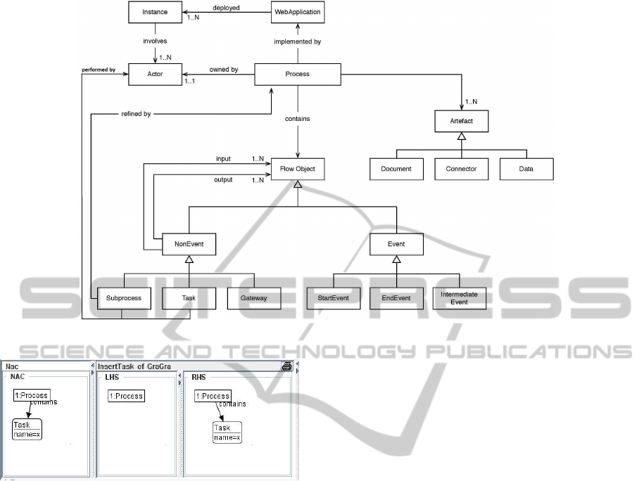
Figure 4: A UML based representation of BPM meta-model.
Figure 5: A rule to insert a task.
3.2 The Composite Change Operations
The composite change operations can be expressed in
the form of compositions of atomic operations. We
did not set a precise or exhaustive taxonomy of these
operations but we consider the most significant and
frequent ones. It is also possible to define new com-
posite change operations.
The example of composite change operations:
• The merger of two tasks
• The decomposition of a task into two
• The merger of two processes
• The breaking down of a task into subprocess.
4 THE CHANGE IMPACT
ANALYSIS
This section deals with the BPM change impact man-
agement. A simulation of the change impact genera-
tion is presented formerly, using graph rewriting rules
and then in later part impact propagation is elaborated
to the various artifacts through the differenttype of re-
lationships.
4.1 The Change Impact Generation
All change operations are defined by the precondi-
tions, which in the case of a graph rewriting rules
consist of the LHS(positive preconditions) and the
NAC (negative preconditions) and the postconditions
symbolized by the RHS. We therefore consider the
impact of a change M given the result of its execu-
tion(symbolized as the RHS), in the case of a viola-
tion of the precondition. In the case of graph rewriting
rules, this is translated into the creation of a node of
Impact type, connected to the nodes affected by the
impact and containing an attribute called explanation
which contains a narrative of the impact (see Fig. 6).
We simulate the creation of the impact by setting rules
without NAC and therefore tolerate the enforcement
of the rule with the result, in addition to that provided
by the original rule, appending a node of impact type
linked to the nodes it affects. In Fig. 6, we define a
rule to delete a task that provokes the creation of an
Impact node affecting the tasks related to the task that
has been deleted.
4.2 The Change Impact Propagation
The change impact propagation is a process of prop-
agating the impact to all nodes indirectly affected by
the impact. This propagation is done through a link or
ChangeManagementofBPM-basedSoftwareApplications
41
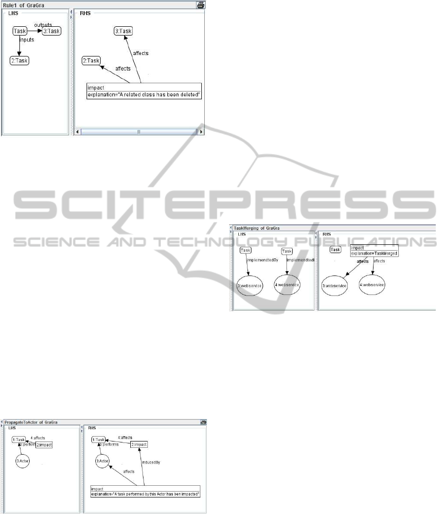
Figure 6: A rule for change impact analysis of a task dele-
tion.
relationship between nodes. Thus, some relationships
are identified as change impact conductor (Ahmad
et al., 2008a) and propagate the impact in one way
or another. For example, the Fig. 7 shows the propa-
gation of the impact affecting a task to the author of
this task with the associated explanation.
We distinguish here two types of change impact
propagations:
• The horizontal change impact propagation is to
propagate the change impact between artifacts be-
longing to the same phase of the development life
cycle of an application. This is the case of the rule
as shown in Fig. 7. It shows the impact propaga-
tion between tasks and actors.
• The vertical change impact propagation corre-
sponds to the change impact flow between arti-
facts belonging to different phases of the develop-
ment life cycle of an application. This is the case
of the change impact propagation between a task
and a web service that implements a part of this
task and vice versa.
Figure 7: A rule for change impact propagation.
To show how we deal the vertical change impact
propagation, we first define a kind of mapping rela-
tionships that are useful for the traceability purpose.
These relationships are :
• The mapedTo relationship between a BPMN pro-
cess and a BPEL process. In fact, we defined a
meta-model of BPEL processes like we have done
with the BPMN but the BPEL process contains
objects like web services, etc.
• The ImplementedBy relationship between a task
of the BPM and a web service of the BPEL.
We know that this set of mapping relationships is a
restrictive one since it is generally possible that a task
may be implemented by more than one web service,
it may also be implemented by a process. In another
hand a BPMN process may be implemented by a set
of BPEL, ones. But we just want to demonstrate the
feasibility of our approach at this initial stage and then
refine it more deeply in the future works.
The mapping relationships are then used by the
graph rewriting rules generating or propagating the
impact. So, the Fig. 8 shows the impact generated
by the composite change consisting of the merging of
two tasks. The question here is what to do with web
services implementing these tasks?
Figure 8: Rule for the impact generated by the composite
change.
On the other hand, we consider three kinds of
change impact propagation processes.
• The total change impact propagation simulates the
change operation and then execute all possible
rules of its impact propagation.
• The selective change impact propagation only
propagates the change impacts induced by a sub-
set of nodes relationships.
• The Propagation of type changes-and-fix(Rajlich
and Gosavi, 2004; Rajlich, 1997) which is to
simulate a change, directly addresses the impact
of this operation (in terms of direct neighbours).
This treatment or correction of the change impact
will be a transaction which itself will directly im-
pact the address, and so on.
5 THE PROTOTYPE
OF VALIDATION
We use the graph rewriting system as a mean to for-
mally describe the BPM change operations. We also
ICEIS2013-15thInternationalConferenceonEnterpriseInformationSystems
42

Figure 9: Screen shot of a change impact propagation scenario in Architect.
use such systems as an execution engine to evaluate
the different strategies we may adopt for the impact
management. For an operational validation of the
proposed change impact analysis and meta-model, we
implement an integrated platform prototype. It allows
friendly experimentations of graph structures associ-
ated to a software development project. Our platform,
named as Architect is a change impact analysis tool
for distributed software applications. It is built as a
set of Eclipse
6
IDE plug-ins. An Eclipse project man-
ages a set of resources that can be source code files,
libraries, BPEL, and BPMN filesetc. Architect ana-
lyzes these heterogeneous sources and parses their el-
ements to represent them as a homogenous interactive
graph. The Architect Graph extension of eclipse visu-
alizes the elements of the corresponding editor view.
This prototype contains a graph editor which provides
in a very simple way the nodes and arcs of the struc-
tural graph.
We have used the Java Universal Net-
work/Graph(JUNG)
7
Framework. This is a software
library that can be re-used for the modeling, analysis,
and the visualization of data as a graph or network.
This library allows to define the structure of data
Graph and also to use certain graph primitives for
the construction of user interfaces associated with the
graph manipulation tools. We used it in interaction
with the built-in capabilities of Java API, as well
as those of other existing third party Java libraries
i.e Drools
8
. We have specialized the class Graph
available in the JUNG library in a class that we
6
http://www.eclipse.org/
7
http://jung.sourceforge.net/
8
http://www.jboss.org/drools/
called ArchitectGraph. The large software related
information can be stored and manipulated through
a semi-automated knowledge-based system. The
Drools is a business logic platform which provides
an integrated unified platform for the graph rewriting
rules, workflow and the event processing. We use it
for writing dynamic expert rules as well as general
rules of propagation to improve the interactivity of
generated graph.
By using our platform, one can friendly specify a
change affecting a node. Which may be a BPM task,
a web service specification, or a Java class, etc. The
various rules implementing the change impact propa-
gation may then be fired. As a result the new graph
is displayed containing nodes of type ”impacted” re-
lated to the different impacted artifacts along with the
explanation of the propagated impact.
6 CONCLUDING REMARKS
AND FUTURE WORK
In this paper, we present an approach based on a
BPM meta-model intended to serve as a BPM arti-
facts repository data schema. We also defined the ini-
tial BPM change operations taxonomy. It involves the
formalization of the change and the analysis of its im-
pact propagation by graph rewriting rules. The graph
rewriting rules have been implemented with AGG that
as a graph rewriting system. This implementation can
be considered as an operational or constructive speci-
fication.
We observe that it is possible to define a change
impact propagation process concerning both the BPM
ChangeManagementofBPM-basedSoftwareApplications
43

processes artifacts and their implementations which
can be BPEL processes, etc.The main concept of our
approach is implemented by a set of tools integrated
as ECLIPSE plug-ins. These plugins are parts of a
more general integrated framework which is built to
deal with the software artifacts change impact propa-
gations.
We are continuing the work by enriching the ap-
proach, in a more detailed way, with the different kind
of mapping relationships related to the BPM artifacts
and their implementation. The main goal is to be
able to automatically track the change impact prop-
agation. To achieve this, we must explicitly represent
knowledge concerningthe semantic of BPM elements
and their relationships. We are then using the BPMN
ontology(Penicina, 2013) that is expressed using the
owl language(Motik et al., 2012). We plan to en-
rich this ontology by concepts representing the var-
ious aspects of change impact and the relationships
propagating such impacts. The use of the owl lan-
guage makes it possible to define, in an explicit way,
the relationship hierarchy based on the impact prop-
agation. It is also possible to explicitly define some
semantical characteristics of relationships like transi-
tivity, etc. The reasoning capabilities provided by the
ontology languages(like owl) may assist the change
experts to define change impact rules.
Another goal is to provide some forward and re-
verse engineering tools in order to implement some
important tasks like defining flexible and adaptable
tools for the generation of BPM implementations and
some others for the generation of BPMs from the pro-
cess implementations.
REFERENCES
Ahmad, A. and Basson, H. (2009). Software evolution mod-
elling: an approach for change impact analysis. In
Proceedings of the 7th International Conference on
Frontiers of Information Technology, FIT ’09, pages
56:1–56:4, New York, NY, USA. ACM.
Ahmad, A., Basson, H., and Bouneffa, M. (2008a). Soft-
ware evolution control: Towards a better identifica-
tion of change impact propagation. In ICET’08: Pro-
ceedings of the 4th IEEE International Conference on
Emerging Technologies, pages 286–291. IEEE Com-
puter Society.
Ahmad, A., Basson, H., and Bouneffa, M. (2009). Rule-
based approach for software evolution management.
In IEEE APSSC 2009: IEEE Asia-Pacific Services
Computing Conference.
Ahmad, A., Basson, H., Deruelle, L., and Bouneffa, M.
(2008b). Towards a better control of change impact
propagation. In INMIC’08: 12th IEEE International
Multitopic Conference, pages 398–404. IEEE Com-
puter Society.
Allweyer, T. (2010). BPMN 2.0 : Introduction to the Stan-
dard for Business Process Modeling. Books on De-
mand, Norderstedt.
Dadam, P., Reichert, M., Rinderle, S., Jurisch, M., Acker,
H., Pser, K. G. A., Kreher, U., and Lauer, M. (2007).
Adept2 - next generation process management tech-
nology. In Proceedings Fourth Heidelberg Innovation
Forum, Aachen. D.punkt Verlag.
DeRemer, F. and Kron, H. (1975). Programming-in-the
large versus programming-in-the-small. SIGPLAN
Not., 10(6):114–121.
Dumas, P., Charbonnel, G., and Calmes, F. (1990). La
m´ethode OSSAD - Pour maˆıtriser les technologies de
l’information - Tome 2: Guide pratique, Les Editions
d’Organisation, Paris.
Emig, C., Momm, C., Weisser, J., and Abeck, S. (2005).
Programming in the Large based on the Business
Process Modeling Notation. In Jahrestagung der
Gesellschaft f¨ur Informatik (GI), Bonn.
Gottschalk, K., Graham, S., Kreger, H., and Snell, J. (2002).
Introduction to web services architecture. IBM Syst.
J., 41:170–177.
Haller, A., Gaaloul, W., and Marmolowski, M. (2008). To-
wards an xpdl compliant process ontology. In SER-
VICES I, pages 83–86.
Juric, M. B. (2006). Business Process Execution Language
for Web Services BPEL and BPEL4WS 2nd Edition.
Packt Publishing.
Lee, Y.-C., Chu, P.-Y., and Tseng, H.-L. (2011). Corpo-
rate performance of ict-enabled business process re-
engineering. Industrial Management and Data Sys-
tems, 111(5).
M. O., H., Deruelle, L., Basson, H., and Ahmad, A. (2010).
A change propagation process for distributed software
architecture. In ENASE 2010: Proceedings of the 5th
International Conference on Evaluation of Novel Ap-
proaches to Software Engineering.
Motik, B., Grau, B. C., Horrocks, I., Wu, Z., Fokoue, A.,
and Lutz, C. (2012). Owl 2 web ontology language:
Profiles. w3c recommendation (27 october 2009).
OMG (2011). Business process model and notation
(bpmn) version 2.0. OMG Document Number: for-
mal/ 2011-01-03, Standard document URL: http://
www.omg.org/spec/BPMN/2.0 Accessed 2011-03-18.
Parmenter, D. (2007). Key Performance Indicators (KPI):
Developing, Implementing,and Using Winning KPIs.
John Wiley & Sons, Inc., New York, NY, USA.
Penicina, L. (2013). Choosing a bpmn 2.0 compatible up-
per ontology. In The 5th International Conference on
Information, Process, and Knowledge Management,,
pages 89 – 96, Nice, France. IARIA.
Rajlich, V. (1997). A model for change propagation based
on graph rewriting. In Proceedings of the Interna-
tional Conference on Software Maintenance, pages
84–91, Washington, DC, USA. IEEE Computer So-
ciety.
ICEIS2013-15thInternationalConferenceonEnterpriseInformationSystems
44

Rajlich, V. and Gosavi, P. (2004). Incremental Change
in Object-Oriented Programming. IEEE Softw.,
21(4):62–69.
Schmidt, D. (2006). Guest editor’s introduction: Model-
driven engineering. Computer, 39(2):25 – 31.
Silver, B. (2009). BPMN Method and Style: A levels-based
methodology for BPM process modeling and improve-
ment using BPMN 2.0. Cody-Cassidy Press.
Van der Aalst, W. M. P. (2003). Patterns and XPDL: A
critical evaluation of the XML process definition lan-
guage. Technical Report BPM-03-09, BPMcenter.org.
Weske, M. (2007). Business process management concepts,
languages, architectures. Springer, 1 edition.
Weske, M. (2012). Business process management architec-
tures. In Business Process Management, pages 333–
371. Springer Berlin Heidelberg.
ChangeManagementofBPM-basedSoftwareApplications
45
