
3D Realtime Simulation Framework for a Wall-climbing Robot using
Negative-pressure Adhesion
Daniel Schmidt, Jens Wettach and Karsten Berns
Robotics Research Lab, University of Kaiserslautern, Gottlieb-Daimler-Str. 48, Kaiserslautern, Germany
Keywords:
Simulation, Wall-Climbing Robot, Negative-Pressure Adhesion, Thermodynamic Model, Visualization.
Abstract:
Simulation frameworks are wide-spread in the range of robotics to test algorithms and analyze system behavior
beforehand – which tremendously reduces effort and time needed for conducting experiments on the real
machines. This paper addresses a component based framework for simulating a wall-climbing robot that uses
negative pressure adhesion in combination with an omnidirectional drive system. Key aspect is the adhesion
system which interacts with the environmental features such as surface characteristics (e. g. roughness) or
defects. An elaborate thermodynamic model provides the basis for a realistic simulation of the airflow between
the virtual environment and the vacuum chambers of the robot. These features facilitate the validation of
closed-loop controllers and control algorithms offline and in realtime.
1 INTRODUCTION
In robotics, simulation frameworks are important
tools to evaluate algorithms e. g. for path-planing
or obstacle avoidance without executing them on the
real machine. This avoids unnecessary stress on the
hardware, reduces testing time and enables develop-
ers to analyze system behavior without endangering
persons, the environment or the robot itself.
State-of-the-art frameworks facilitate a physically
realistic 3D simulation of all kinds of robots, e. g.
wheel-driven systems, walking machines, flying and
underwater robots, as well as sensor systems and ma-
nipulators. But so far, support for the simulation of
airflow and resulting negative pressure adhesion in the
context of climbing robots is still missing.
This paper presents a framework for simulating
CROMSCI
1
– a complex wheel-based climbing robot
with an omnidirectional drive, active sliding suction
cups and environmental sensors. Its key aspects are
seven individual adhesion chambers, inflatable seal-
ings for leak-tightness, built-in suction engines evac-
uating a large vacuum reservoir and three unsprung
steerable driven wheels (Schmidt et al., 2011). In ad-
dition to experiments performed with a real prototype,
especially the simulation of the interaction between
adhesion system and surface allows extensive tests of
safety strategies and closed-loop controllers.
1
http://agrosy.cs.uni-kl.de/cromsci/
The paper is organized as follows: Section 2 gives
an overview of existing 3D simulation tools and appli-
cations related to the adhesion mechanism of climb-
ing robots. The general concept of the simulation
is presented in section 3. Section 4 describes the
setup of the virtual environment and robot model us-
ing the SIMVIS3D framework. Afterwards, section 5
presents the thermodynamic model, leakage simula-
tion and physical aspects of the drive system. Sec-
tion 6 shows the interaction of all simulation compo-
nents in terms of some experiments. The final conclu-
sion follows in section 7.
2 RELATED WORK
Gazebo (Koenig and Howard, 2004) is a simulator
for multiple robots in arbitrary 3D environments with
an interface for the control framework ROS. It sup-
ports realistic noisy data for different kinds of sen-
sors, e. g. sonar, laser scanners, cameras, Kinect,
GPS, RFID and inertial systems as well as rigid-body
dynamics for object manipulation via the ODE or
Bullet engine. SimRobot (Laue and R
¨
ofer, 2008)
is a similar tool based on ODE that focuses mainly
on the RoboCup Soccer scenario via a realistic sim-
ulation of camera disturbances and actuator friction.
USARSim (Wang et al., 2003) is the simulation tool
for the RoboCup Rescue scenario. It is based on the
Unreal game engine and uses Karma for physics.
184
Schmidt D., Wettach J. and Berns K..
3D Realtime Simulation Framework for a Wall-climbing Robot using Negative-pressure Adhesion.
DOI: 10.5220/0004444401840191
In Proceedings of the 10th International Conference on Informatics in Control, Automation and Robotics (ICINCO-2013), pages 184-191
ISBN: 978-989-8565-71-6
Copyright
c
2013 SCITEPRESS (Science and Technology Publications, Lda.)

Concerning commercial tools, Webots (Michel,
2004) focuses on research robots as Aibo, Pioneer or
Kuka youBot. It uses ODE and provides support for a
rather complete set of sensors and actuators. Vortex
2
is tailored to heavy industrial equipment as cranes, ex-
cavators and military vehicles. It comes along with
its own physics and particle simulation for fluids, dust
and shapeable soil. Finally V-REP (Freese et al., 2010)
is a feature-rich 3D simulator for wheel-driven, walk-
ing and flying robots with support for different kinds
of manipulators, sensors and dynamic particles for jet
engines, either based on ODE or Bullet.
All these tools have the restriction of system dy-
namics to rigid bodies in common. Although suffi-
cient for collision detection and pick-and-place tasks,
negative pressure adhesion as in the case of CROMSCI
cannot be modeled. Even the support for particle sys-
tems is not suited for simulating the airflow in the vac-
uum chambers since this is a thermodynamic problem
and not related to the particle impulses.
Consequently in the context of climbing robots
there only exist individual solutions for computing the
adhesion forces. (Longo et al., 2005) uses Simulink
to simulate the drive system of the Alicia
3
robot, but
only with a simplified model for the wheel-wall con-
tact and none for the suction cups. (Pretto et al., 2008)
calculates the contact forces between the feet of a six-
legged climbing robot and a set of adhesive objects
via continuous mechanics theory.
(Wettach et al., 2005) presents the thermodynamic
model of a wall-climbing robot with 7 vacuum cham-
bers and one reservoir. To evaluate its power a sim-
ple 2D simulation had been developed where leakages
are only caused by artificial cracks of a certain depth,
bounded by two parallel infinite lines. Hence the leak-
age areas are calculated geometrically as intersection
of crack borders and curved line segments of the dif-
ferent sealing sections. Besides the model had been
evaluated on a prototype with only one suction cup.
Compared to that work the paper at hand describes
a rather realistic simulation of sealing leakages caused
by any kind of surface defect (e. g. holes, steps,
grooves) modeled in a virtual 3D environment. Their
effects are calculated efficiently via a virtual depth
camera. Furthermore the dynamics of the drive sys-
tem are now simulated via a physics engine that takes
the downforce resulting from the vacuum chambers
and wheel slippage into account. Finally the whole
simulation has been evaluated on a highly sophisti-
cated prototype which had been constructed in the
meanwhile as 1:1 implementation of the proposed
seven chamber model (see figure 10).
2
http://www.vxsim.com/en/software
3 CONCEPT
The software of CROMSCI has been implemented
within the MCA framework
3
as depicted in figure 1.
The embedded simulation is divided into four logical
blocks illustrated as gray boxes. On the highest level
ideal actuators are simulated for the drive system, the
tool center point (TCP), suction engines and negative
pressure valves. User commands are executed by the
actuators with a certain delay and within individual
velocity limits. The state of the drive units (orien-
tation and velocity of each wheel) can optionally be
used as input for a physics engine like Nvidia PhysX
to determine wheel slippage, collisions and the result-
ing robot pose based on collision and friction mod-
els. Otherwise the robot odometry has to be computed
manually as input for subsequent simulation steps.
Figure 1: Components of the simulation framework (gray).
Afterwards, the calculated robot pose is given
to the SIMVIS3D framework containing the visual
scene representation. Via this framework it is possi-
ble to both simulate environmental sensors like laser
scanners or to visualize the scene. In the context of
adhesion simulation SIMVIS3D is used to create a
depth image of the surface below the robot, which is
the basis for calculating sealing leakages. The sim-
ulated leakage values as well as the state of suction
engines and chamber valves are given to a thermo-
dynamic simulation. Based on the simulated airflows
and negative pressure values an overall adhesion force
can be determined which acts as robot downforce in
the physical simulation. The modular structure of the
simulation framework allows it to replace single com-
ponents by real hardware to test e. g. the real chamber
valves via simulated pressure values. The following
sections introduce these components more detailed.
3
http://rrlib.cs.uni-kl.de/mca-kl/
3DRealtimeSimulationFrameworkforaWall-climbingRobotusingNegative-pressureAdhesion
185

4 SIMULATION FRAMEWORK
SIMVIS3D
4
is a framework for simulating and visu-
alizing the interaction of objects in a 3D scene based
on the OpenInventor standard (OIV) using COIN3D
5
.
Its core data structure is a scene graph for arranging
elements in the simulated environment and for man-
aging scene changes at runtime. Scene elements are
all kinds of OIV nodes: Visual 3D bodies as well as
modifiers (i. e. transform nodes) that influence the rel-
ative pose of the bodies.
4.1 Scene Descriptions
SIMVIS3D consists of an easy-to-use XML scene de-
scription for setting up the scene at simulation startup
and of a sound API for applying changes online.
These changes are classified as structural if elements
are added to or removed from the scene and as para-
metric if attributes of existing scene elements are
changed, e. g. the six values of the transform node
that defines the 3D pose of a robot. All elements that
are specified in the XML file or added at runtime are
addressed by a unique name through the SIMVIS3D
API. Each non-modifier node contains a hook (de-
noted as insertion point) to define the connection of
scene elements. This hook is used to locate the cor-
rect position in the scene graph. Besides, it serves to
make element names unique in the scene so that they
can be accessed by the user.
The following excerpt of CROMSCI’s XML de-
scription illustrates these scene elements:
<part file="outdoor_scene.iv" name="WORLD"
attached_to="ROOT" offset="0 0 0 0 0 0"/>
<part file="cromsci.iv" name="CROMSCI"
attached_to="WORLD" offset="-1 8 7 0 -90 0"/>
<part file="drive_unit.iv" name="DRIVE_FRONT"
attached_to="CROMSCI" offset=".3 0 0 0 0 0"/>
<part file="manipulator.iv" name="TCP"
attached_to="CROMSCI" offset="0 0 0 0 0 0"/>
<part file="empty_node.iv" name="DEPTH_CAMERA"
attached_to="CROMSCI" offset="0 0 .1 0 0 0"/>
Visual elements are specified by the part token.
The file attribute indicates the source of the OIV
subtree that represents the new element. It is mounted
into the scene graph as child of the insertion point
node given by the attached_to parameter, taking the
given static pose offset into account. The ROOT node
is the default top node of the scene graph. Finally the
name parameter identifies the added part. The use of
capital letters is just a convention to highlight parts
since they are mainly used as hooks.
4
http://rrlib.cs.uni-kl.de/software/
simvis3d/
5
https://bitbucket.org/Coin3D/coin
Figure 2: Wireframe model of CROMSCI and a bridge in-
cluding a band of rough structured surfaces (top) and ren-
dered visualization (bottom).
In the example first an outdoor scene (floor, plants,
bridge, pylon) is added to the root as WORLD, then
the robot is added to the scene as CROMSCI. Its
drive mechanism consists of three units, each with a
driven wheel. They are equally distributed on a cir-
cle (see figure 6). Here, only the front drive unit is
shown. Actually, the same OIV file is added twice
more as left and right unit with corresponding names.
For example, the front drive is identified distinctly
as ROOT:WORLD:CROMSCI:DRIVE_FRONT. Afterwards
the manipulator is put into action as TCP and then an
empty node is applied as anchor for a depth camera.
The latter does not represent a visible node since it
just serves as virtual hook for the respective sensor.
In figure 2 the wireframe model and rendered view of
the scene are shown exemplarily.
Whereas the visual objects represent the static part
of a scene, modifier elements define the relative pose
of subgraphs. Thus they set up the animation of a
scene. The modifiable attributes of the elements, i. e.
numeric values of transform nodes, are collected in
a data array. A link to the values of a specific ele-
ment can be retrieved via its unique name through the
SIMVIS3D API. Therefore, scene changes may be
applied from any point in the user code.
In case of CROMSCI the following elements are
defined in the XML file:
<element name="cromsci_pose" type="3d Pose"
angle_type="rad" attached_to="CROMSCI"/>
<element name="drive_fr_pose" type="3d Pose"
angle_type="rad" attached_to="DRIVE_FRONT"/>
<element name="tcp_pose" type="3d Pose"
angle_type="rad" attached_to="TCP"/>
<element name="switch" type="Switch"
ICINCO2013-10thInternationalConferenceonInformaticsinControl,AutomationandRobotics
186

switch_mode="-3" attached_to="CROMSCI"/>
Each element is attached to one of the parts in-
troduced above. The 3d Pose elements define the
(x,y,z) position and (roll, pitch,yaw) orientation (an-
gle values in radians) of their hook. The switch el-
ement is used to temporarily deactivate parts of the
scene during rendering (according to the original OIV
SoSwitch node ’-3’ means ’on’ and ’-1’ means ’off’).
With this setup the climbing robot, its wheels and
manipulator can be moved arbitrarily in the scene and
the result can be visualized online via a plugin in
the MCA user interface. The natural kinematic con-
straints have to be calculated outside SIMVIS3D. In
case of CROMSCI this is done in the Drive and TCP
Simulation block shown in figure 1.
4.2 Sensor Data
Apart from the animated 3D scene simulation and
visualization the main benefit of SIMVIS3D is the
generation of close-to-reality sensor data. So far,
cameras and distance sensors (ultrasound, laser scan-
ners, depth cameras) are supported. In the case of
CROMSCI the following sensors are relevant:
<distance_sensor name="laser_scanner"
max_distance="4" scan_angle_range="240"
angular_resolution="0.352423"
offset="0 0 0.35 0 20 0" attached_to="TCP"/>
<camera name="depth_cam" type="orthographic"
near_limit="0.1" attached_to="DEPTH_CAMERA"/>
The first one is a simulated 2D laser scanner with
angular range of 240
◦
and resolution of 0.35
◦
, cor-
responding to the real Hokuyo URG-04LX scanner.
It is attached to the TCP with the given static offset.
Hence, the scanner moves over the ground as soon as
the robot and/or the manipulator is actuated. The sec-
ond sensor is an orthographic depth camera attached
to the virtual hook. Its data is not exported as from a
real sensor, but used internally to calculate the leak-
age situation of the vacuum chamber sealings arising
from the roughness of the ground (see section 5).
4.3 Climbing Robot Scene
The virtual environment of CROMSCI contains differ-
ent components for simulation and decoration. Fig-
ure 3 shows the basic wireframe model of the robot
and its surroundings (trees, bridge elements, ground).
The bridge pylon consists of single cubes, each with
an edge length of 2 m and one structured face. Its de-
fects are modeled as indentations of the rigid body
and visualized via textures. This enables to exchange
single parts of the bridge for different test conditions.
Figure 3: Wireframe model of the environment including
the cube elements of the bridge (top) and detailed view of
CROMSCI on a rough structure mesh (bottom).
Once created, one can insert a cube at any position
and rotate it via the XML scene description as follows:
<part file="cube_crack_01.iv" name="CUBE"
attached_to="BRIDGE" offset="2 0 0 0 0 0"/>
<part file="cube_crack_02.iv" name="CUBE"
attached_to="BRIDGE" offset="4 0 0 0 0 270"/>
<part file="cube_concrete_01.iv" name="CUBE"
attached_to="BRIDGE" offset="6 0 0 0 0 0"/>
Again, each CUBE is attached to the BRIDGE hook
with a certain pose offset. Since these parts do not
have to be addressed within the simulation for ma-
nipulation, they do not need unique names. For vi-
sualization, some additional components are added to
the scene in order to create a nice view on the virtual
environment. Previous figure 2 shows the wireframe
model of CROMSCI and the bridge surface as well as
the rendered view including trees, textured surfaces
and backgrounds. This visualization is rendered in
realtime and is used to observe the simulated scene.
So far, more than 50 different cubes have been cre-
ated using the modeling tool Blender and integrated
into the scene description as OpenInventor files. Ex-
amples are given in figure 4.
Figure 4: Surface patches with a general roughness, a
straight crack and a complex crack structure (from left).
3DRealtimeSimulationFrameworkforaWall-climbingRobotusingNegative-pressureAdhesion
187
5 INTERACTION OF ROBOT
AND ENVIRONMENT
The simulation of robot interaction has to consider
different aspects. The most interesting components
are those which are responsible for robot adhesion,
namely the internal airflow and the occurring leak-
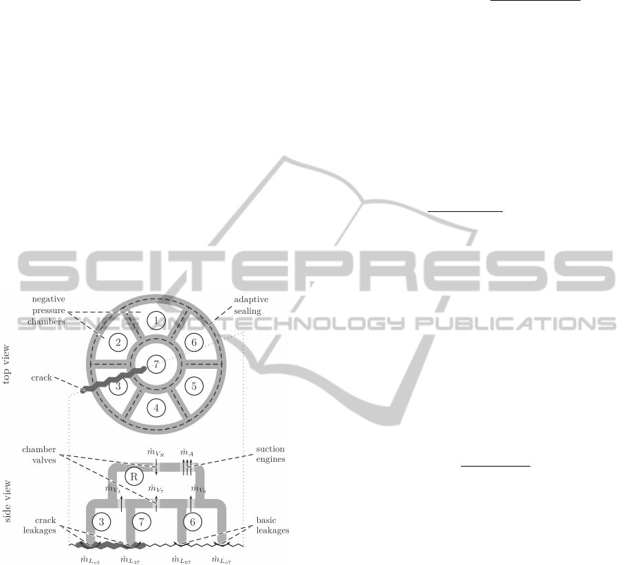
ages. Figure 5 gives a structural view on the adhe-
sion components of CROMSCI. The top view shows
the seven negative pressure chambers with one cen-
tral chamber. Below, the side view illustrates the dif-
ferent mass flows via valves ˙m
V
i
and leakages ˙m
L
i j
at
the sealing areas. ˙m
A
denotes the amount of air which
is taken out of the vacuum reservoir by the suction
engines (Wettach et al., 2005). In general, basic leak-
ages occur even on a perfect flat structure due to the
type of sliding coating of the sealing. This leakage
increases with surface roughness, defects and gaps.
Figure 5: Structural setup of CROMSCI’s adhesion compo-
nents: Adhesion chambers 1 to 7 and reservoir R with an
exemplary crack below chambers 3 and 7.
5.1 Airflow and Adhesion Forces
Basis of the interaction model between robot and en-
vironment is the first fundamental theorem of ther-
modynamics and Bernoulli’s equation describing the
steady state flow of an ideal fluid. The mass flow
˙m
i j
between two volumes i and j depends, accord-
ing to equation 1, on the current pressure values p
i
and p
j
and the area of airflow A
i j
between both vol-
umes. This can e. g. be the sealing leakage connecting
one chamber to the ambient air, or the valve opening
area between chamber and negative pressure reser-
voir. Here, ρ
air
is the density of air.
˙m
i j
= sgn(p
i
− p
j
) ·A
i j
·
q
2 ·ρ
air
·
p
i
− p
j
(1)
It is now possible to determine the pressure
change ˙p
i
of volume i based on the airflow ˙m
i j
ac-
cording to equation 2. In here, κ
air
= 1.402 denotes
the adiabatic index of air, R
air
is the specific gas con-
stant, T
air
the temperature and V
i
the volume of i. The
sum goes over all other volumes k including the ambi-
ent air. In case of no direct connection between both
volumes k and i (if they are no neighbors) the area A
ik
and, therefore, also the mass flow ˙m
ik
is zero.
˙p
i
=
κ
air
· R
air
· T
air
V
i
∑
k
˙m
ik
(2)
To simplify the thermodynamic model, some of
these parameters are assumed to be constant for
simulation purposes: Density ρ
air
= 1.1883 kg/m
3
,
gas constant R
air
= 287.058 J/(kg K) and temperature
T
air
= 293.15
◦
K. More details about the modeling it-
self can be found in (Wettach et al., 2005). Based
on the given pressure values p
i
of each chamber it is
possible to calculate the total affecting downforce F
(equation 3) and its point of action
~
P
F
(equation 4):
F =
7
∑
i=1
F
i
=
7
∑
i=1
((p
o
− p
i
) ·A
i
) (3)
~
P
F
=
7
∑
i=1
~
P
i
·
(p
o
− p
i
) ·A
i
F
(4)
Here, p
o
denotes the pressure value of ambient air
(≈ 100000 Pa), A
i
is the suction area of chamber i and
~
P
i
is the chamber center point related to robot coordi-
nates. The general goal of the closed-loop adhesion
controller is to guarantee a certain downforce and to
balance the force equally among the three wheels so
that the point of action lies in the robot center.
5.2 Sealing Leakages
The leakage between sealing and surface depends on
two aspects: The structure of the surface and on the
sealing adaptability. Since the interaction between ad-
hesion system and surface is not sufficiently known
– especially with respect to friction and sliding char-
acteristics as well as for the influence of different
surfaces on the sealing leak tightness – a simplified
sealing model is used. The idea is to take a picture
via a simulated orthographic camera (see section 4)
of the ground below the robot and to transform the
depth-buffer from rendering into height data. The
depth camera has a resolution of 256× 256 pixels and
ICINCO2013-10thInternationalConferenceonInformaticsinControl,AutomationandRobotics
188

Figure 6: Depth image including sealing area and drive
units (left) and resulting leakages (right).
surveys an area of 80 × 80 cm
2
as depicted in exam-
ple figure 6, which corresponds to the dimensions of
the real robot. Here, one can see the surface height
as grayscale image with an overlay of the individual
sealing edges (as black and white lines). In the mid-
dle of the white marked chambers the three wheels
are visible. The other components of the robot chas-
sis have to be removed temporarily by the described
switch to take the depth image, otherwise the robot
interior would be in sight. The height resolution de-
pends on the near and far limits of the simulated cam-
era. In the present case the observed range is ±5 cm
resulting in a z-resolution of 0.39 mm.
The next step is to simulate the sealing adaption
to this height. In reality, the leak tightness depends
on the rubber material of the sealing, the induced air
pressure and the sliding coating of the sealing. Since
these characteristics cannot be emulated completely,
an approximation is used which allows the simulated
sealing to adapt only a specific portion from one point
to another. Depending on a maximum height differ-
ence between one pixel and another the height values
of each sealing pixel are calculated:
1. set all sealing pixel heights to surface
. heights below sealing
2. repeat
3. reset changed flag
4. for each sealing pixel
5. if difference to highest neighbor pixel
. larger than maximum height difference
6. set current sealing pixel height to
. highest one minus maximum difference
7. set changed flag
8. until not changed
The result of this calculation is shown in figure 6
on the right side. Leak-tight sealing pixels (the dis-
tance between ground and sealing is nearly zero) are
drawn solid black whereas permeable sealing pixels
are colored gray to white depending on the size of the
gap. Of course, the total amount of maximal indenta-
tion and extrusion of the sealing is limited and has to
be considered depending on the real sealing setup. In
the present case the maximum capability of the seal-
ing lies at about ±5 mm. Therefore, cracks deeper
than this cause a gap which cannot be proofed. Based
on these sealing pixels the final leakage L
i
of each
sealing section S
i
can be calculated (equation 5).
L
i
= l
i
·
L
basic
+ κ ·
∑
j∈S
i
h
s
( j) − h
g
( j)
|S
i
|
!
(5)
Here, l
i
is the length of the sealing segment, L
basic
a basic leakage caused by the sliding coating (the seal-
ing must not be 100% leak-tight otherwise the robot
would be stuck), κ is a multiplication factor normally
set to 1 which can be adapted for debugging purposes.
The sum goes over all pixels j which belong to seal-
ing segment S
i
and depends on the height value of
the sealing pixel h
s
( j) and of the ground pixel h
g
( j)
divided by the total amount of pixels |S
i
| of that seg-
ment.
The pressure change ˙p
i
of a chamber is then cal-
culated according equation 2 with the leakage areas
of the sealing segments of that chamber and the valve
area connecting this chamber to the reservoir. In the
case of chamber 1 one receives five areas for inter-
changing air pressure resulting in the sum of airflow
given in equation 6 (compare figure 5).
∑
k
˙m
1k
= ˙m
L
12
+ ˙m
L
16
+ ˙m
L
17
+ ˙m
L
1o
+ ˙m
V
1
(6)
Here, ˙m
V
1
denotes the support of negative pressure
from the reservoir which is controlled via the valve.
On the other side, ˙m
L
1o
is the amount of air lost to
the outside ambient air. If all chamber pressures are
balanced equally, the remaining airflow between the
chambers is zero. Otherwise, also these areas produce
a certain loss or support of pressure, depending on the
individual chamber pressures in left and right neigh-
bor ( ˙m
L
12
and ˙m
L
16
) or the center chamber ( ˙m
L
17
).
5.3 Actuators and Robot Behavior
Depending on the real hardware settings all actuators
are simulated with certain limitations of acceleration,
velocity or position. Therefore, all desired commands
for drive steering or valve positioning are executed
with a certain delay. Despite this, the actuators are re-
garded as ideal hardware without tolerances, runtime
errors or defects. But it is possible to replace these
simulation elements by those producing errors with
given failure rates to analyze their effect.
To simulate the system behavior on affecting
forces and motions it is possible to apply a physics
engine. So far, the climbing robot simulation frame-
work uses PhysX
6
from Nvidia, but other engines like
6
http://developer.nvidia.com/physx
3DRealtimeSimulationFrameworkforaWall-climbingRobotusingNegative-pressureAdhesion
189
Newton Game Dynamics
7
could be used in combina-
tion with SIMVIS3D as it has been done in other re-
search projects before (Wettach et al., 2010). In gen-
eral, the physics engine has to consider and contain
the following aspects: Collision models of robot and
environment, affecting forces (gravity and adhesion
force), friction models and wheel orientation and ve-
locity for locomotion.
Due to simplicity, CROMSCI does not use the
same rough structured mesh for physical simulation.
The ground surface is assumed to be plane to simplify
the wheel-ground interaction. The friction caused by
the sealing is also not considered here which affects
the robot in real life. Depending on the selected fric-
tion values between wheels and surface and on the
generated downforce one receives a different robot
behavior relative to its motion direction and gravity.
For instance, the wheel slip is high while driving up,
since the robot has to overcome gravity. In the same
way it falls down if the adhesion force is too low.
For debugging purposes it is possible to observe
the current state of the physical simulation during run-
time via a visualization window showing the complete
scene with all actors. One can pause the simulation,
walk through the scene and read out current values
like pose or velocity of each component. It is also
possible to change e. g. the gravity value during run-
time or apply an impact to a simulated body.
6 APPLICATION
The presented simulation framework has been created
to test control algorithms of CROMSCI offline without
the real machine. Figure 7 shows the graphical user
interface (GUI) of CROMSCI with a view on the 3D
scene and the current robot state. One main appli-
cation is the validation of closed-loop adhesion con-
trollers. In figure 8 one can see an experimental run
in which the simulated robot is driven downwards the
rough wall facing a deep crack. The left circular view
shows the state of the seven chambers of the adhesion
system. The darker the color, the lower the pressure.
Numbers 2, 4 and 6 indicate the associated chambers,
whereas the dimensions of the black circles in non-
labeled chambers 1, 3 and 5 illustrate the downforce at
the corresponding wheel. In the first line, this down-
force is balanced out by a stronger adhesion at the top
chambers (darker color of chambers 3, 4 and 5 com-
pared to 1, 2 and 6) to counteract robot tilt. In the
second row, the bottom chambers are located on the
crack and lose negative pressure (white chambers).
7
http://www.newtondynamics.com
Figure 7: GUI with visualization plugins of the simulated
scene (middle), control elements (left), and state informa-
tion of adhesion (top left) and sealing simulation (top right).
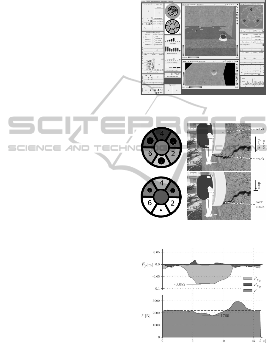
Figure 8: Screenshots of experiment showing the simulated
robot CROMSCI driving to a deep crack (right) and current
states of the negative pressure chambers (left).
Figure 9: Progress of simulated downforce F and its point
of action
~
P
F
during the presented experiments. Robot tilt
leads to a shifted point of downforce in vertical direction
from seconds 4 to 12.
ICINCO2013-10thInternationalConferenceonInformaticsinControl,AutomationandRobotics
190

Figure 9 illustrates the progress of the downforce
value F and its point of action
~
P
F
. It can be seen
that the resulting values are very realistic: The to-
tal amount of downforce F is reduced from desired
2 200 N to 1 760 N and the x position of the point of
action (P
F
x
) moves about 8 cm below the robot center.
Figure 10: Real climbing robot CROMSCI navigating on a
concrete wall.
In the latest history, the simulation system has
e. g. been used to validate safety measures and risk
prediction methods (Schmidt, 2013) or to perform a
foresighted analysis of the terrain. The accuracy of
the thermodynamic model of the vacuum system it-
self has been proven in earlier experiments (Wettach
et al., 2005). The complete simulation framework
is accurate enough to optimize the control software
in the simulation, so that only some fine-tuning is
needed to apply these algorithms on the real machine
depicted in figure 10. Some demonstration videos
8
of CROMSCI in operation prove this transferability of
control algorithms from simulation to reality.
7 CONCLUSIONS
This paper presented a novel framework on the ba-
sis of SIMVIS3D for simulating a climbing robot
using negative pressure adhesion and an omnidirec-
tional drive system. It could be shown that the system
is able to simulate the airflows and pressure changes
of a complex vacuum system with seven suction cups
and one reservoir. The structure of the ground has a
direct impact on the leakage values in order to model
different surface characteristics. Hence, this tool fa-
cilitates the development of control algorithms inde-
pendent of the real robot and enables an offline and
realtime validation in arbitrary 3D environments.
Further work will focus on a porting to FINROC
9
and an easier handling of the physical simulation,
8
http://agrosy.cs.uni-kl.de/en/galerie/
cromsci-medien/
9
http://www.finroc.org
since the Blender export of collision objects does not
include joints. Additionally, a new robot prototype is
under construction: Its control software will be opti-
mized using this tool first, before executing and fine-
tuning it on the real system.
ACKNOWLEDGEMENTS
This research was funded by the German Bundesmin-
isterium f
¨
ur Wirtschaft und Technologie (BMWi), Zen-
trales Innovationsprogramm Mittelstand (ZIM).
REFERENCES
Freese, M., Singh, S., Ozaki, F., and Matsuhira, N. (2010).
Virtual robot experimentation platform v-rep: A ver-
satile 3d robot simulator. In International Conference
on Simulation, Modeling and Programming for Au-
tonomous Robots (SIMPAR).
Koenig, N. and Howard, A. (2004). Design and use
paradigms for gazebo, an open-source multi-robot
simulator. In International Conference on Intelligent
Robots and Systems (IROS).
Laue, T. and R
¨
ofer, T. (2008). Simrobot - development and
applications. In International Conference on Simu-
lation, Modeling and Programming for Autonomous
Robots (SIMPAR).
Longo, D., Muscato, G., and Sessa, S. (2005). Simula-
tion and locomotion control for the alicia3 climbing
robot. In International Symposium on Automation and
Robotics in Construction (ISARC).
Michel, O. (2004). Webots: Professional mobile robot sim-
ulation. International Journal Of Advanced Robotic
Systems, 1(1).
Pretto, I., Ruffieux, S., Menon, C., Ijspeert, A., and
Cocuzza, S. (2008). A point-wise model of adhe-
sion suitable for real-time applications of bio-inspired
climbing robots. Journal of Bionic Engineering, 5.
Schmidt, D. (2013). Safe Navigation of a Wall-Climbing
Robot - Risk Assessment and Control Methods. Dr.
Hut Verlag, Munich, Germany.
Schmidt, D., Hillenbrand, C., and Berns, K. (2011). Om-
nidirectional locomotion and traction control of the
wheel-driven wall-climbing robot cromsci. Robotica
Journal, 29(7).
Wang, J., Lewis, M., and Gennari, J. (2003). A game engine
based simulation of the nist urban search and rescue
arenas. In Winter Simulation Conference.
Wettach, J., Hillenbrand, C., and Berns, K. (2005). Thermo-
dynamical modelling and control of an adhesion sys-
tem for a climbing robot. In International Conference
on Robotics and Automation (ICRA).
Wettach, J., Schmidt, D., and Berns, K. (2010). Simulating
vehicle kinematics with simvis3d and newton. In In-
ternational Conference on Simulation, Modeling and
Programming for Autonomous Robots (SIMPAR).
3DRealtimeSimulationFrameworkforaWall-climbingRobotusingNegative-pressureAdhesion
191
