
Novel Virtual Training System to Learn the Sway Suppression
of Rotary Crane by Presenting Ideal Operation
of Joystick or Visual Information
Tsuyoshi Sasaki, Shoma Fushimi, Yong Jian Nyioh and Kazuhiko Terashima
The Mechanical Engineering Department, Toyohashi University of Technology, Toyohashi, 441-8580, Japan
Keywords: Rotary Crane, Oscillations, Human-Machine Interface, Virtual Reality, Teaching.
Abstract: In this paper, we propose a novel virtual training system capable of shortening the training period of
unskilled crane operators. First, a simulator representing the motion behavior of load and boom during
transfer operation in crane’s cockpit is newly built. Second, referring to such the sway suppression skill
taught in crane driving school, sway suppression control input is theoretically derived. Thirdly, a learning
support method with ideal operation of joystick or visual sensory information to facilitate acquisition of the
sway-suppression skill for unskilled operators is proposed. Finally, a lot of experiments were performed to
validate the effectiveness of the proposed learning support method.
1 INTRODUCTION
Rotary cranes are widely use c d at factories,
harbors, and construction sites to load and unload
cargo. Figure 1 shows a rotary crane. A rotary crane
performs boom rotation, boom hoisting and load
hoisting. Owing to its simple structure, a rotary
crane can be easily disassembled, transported, and
reassembled. Another big advantage of a rotary
crane is that the very large workspace is achieved
with a relatively small footprint.
However, owing to acceleration or deceleration
and centrifugal force, load sway is often generated
during transport operations. When load sway is
generated, it brings the problems on the accuracy of
load to target position, work efficiency and safety.
To solve these problems, it becomes important for
crane operators to acquire sway suppression skill,
and furthermore, acquisition of the skill in short
training period is also needed.
In regard to how this skill is acquired, training
methods are frequently employed in which actual
crane are used, but such methods involve a risk of
accidents during the training period. In view of the
safety hazard, various virtual crane simulators have
been developed that enable training to be conducted
without the training of actual cranes. In J.Y Huang et
al., the development of the training simulator with
high realistic sensation where the beginner operator
Figure 1: A rotary crane in the construction site.
could learn the skill of crane operation beforehand is
attracting much attention (Jiung et al., 2003). In
M.F.Daqaq et al., a virtual simulation of a ship-
mounted crane is carried out in Cave Automated
Virtual Environment (CAVE) (Mohammed et al.,
2003). A six degrees of freedom motion base was
used to simulate the motion of a ship. The
simulation serves as a platform for studying the
dynamics of ships and ship-mounted cranes under
dynamic sea environments, and also as a training
platform for operators of ship-mounted cranes.
Although those simulators perform well in terms of
realistic sensation, the training function is
insufficient. Thus, unskilled operators have to
acquire the sway suppression skill by trial and error.
As a result, a long period of training is needed to
acquire the sway suppression skill. Terashima’s
group researches about shipboard crane training
simulator for beginners (Iwasa et al., 2010; Young
Jian et al., 2011). However, these basic studies are
58
Sasaki T., Fushimi S., Jian Nyioh Y. and Terashima K..
Novel Virtual Training System to Learn the Sway Suppression of Rotary Crane by Presenting Ideal Operation of Joystick or Visual Information.
DOI: 10.5220/0004444500580065
In Proceedings of the 10th International Conference on Informatics in Control, Automation and Robotics (ICINCO-2013), pages 58-65
ISBN: 978-989-8565-71-6
Copyright
c
2013 SCITEPRESS (Science and Technology Publications, Lda.)

Figure 2: Schematic of rotary crane for a load position
model.
unmatched with the actual cockpit view of a crane,
because the simulator is built as the operator view
position fixed around a crane. In addition to this fact,
the interface of the training system was only the one
with the presence of ideal operation of joystick
information, and therefore the comparison and
consideration of interface with the presence of other
information were highly demanded.
The purpose of the present study is to develop a
simulator capable of shortening the training period
for unskilled crane operators for rotary cranes. First,
we create a virtual crane simulator using a rotary
crane model. Display on crane of simulator is given
by viewing from the cockpit which is rotated by
crane, while the display on crane of simulator in the
author’s former researches (Iwasa et al., 2010;
Young Jian et al., 2011) was given by the fixed
cockpit such that cockpit was set on the ground.
Next, sway suppression control input is derived
theoretically. Thirdly, using this control input, we
propose novel two learning support methods that
present ideal operation of joystick or visual sensory
information to facilitate acquisition of the sway
suppression skill for unskilled operators. For the
former presentation of ideal operation of joystick
information, control input with anti-sway against
centrifuged force is reproduced by using an active
joystick. Active Joystick is automatically moved by
using the inverse kinematics of joystick’s motor
model, and operators can naturally learn the ideal
operation by holding joystick. On the other hand, for
the latter presentation of visual information, control
input is shown by an indicator on computer display.
Unskilled crane operators are able to acquire the
sway suppression skill by spontaneously operating
the joystick following to the visual guidance from
the indicator. The usefulness of the proposed method
is demonstrated through various simulation
experiments.
2 DYNAMICS OF ROTARY
CRANE
The motion of rotary crane is different from the
linear motion of an overhead crane or a gantry crane.
In the case of a rotary crane, the motion of the load
has an arc-like trajectory, and considering the effect
of centrifugal force, it is necessary to model the load
sway as a circular cone pendulum. A diagrammatic
illustration of a rotary crane is shown in Figure 2. In
addition, the system is simplified by the following
assumption.
A crane is a rigid body and, considering the load
is a mass point, the rope's weight, deflection and
elasticity are ignored. The friction and backlash for
the power transmission device are ignored. Boom tip
position and load position are represented by
Equations (1) and (2). The equation of swing angle
of a load is represented by Equations (3) and (4) (see
Shen et al., 2003).
Model of Boom tip trajectory:
.sin
~
,cossin
~
,coscos
~
B
B
B
LHz
Ly
Lx
(1)
Model of load position:
.coscos
~
,sincos
~
,sin
~
lzz
lyy
lxx
(2)
Model of swing angle of load:
,coscossinsin2
sinsincos
tansectantansin2
sintansintansincos
2
2
l
lLl
gl
lll
B
(3)
.cos2sincossin
tantancossinsincos
tancossincoscos
2
lllL
g
l
B
(4)
where
zyx
~
,
~
,
~
[m] is three-dimensional coordinate of
Boom tip position, [m] is three-dimensional
coordinate of load position, L
B
[m] is length of
Boom, θ [rad] is rotary angle, φ [rad] is Boom angle,
l [m] is length of rope, α [rad] is sway angle of
radius direction, and β [rad] is sway angle of slew
direction.
NovelVirtualTrainingSystemtoLearntheSwaySuppressionofRotaryCranebyPresentingIdealOperationofJoystickor
VisualInformation
59
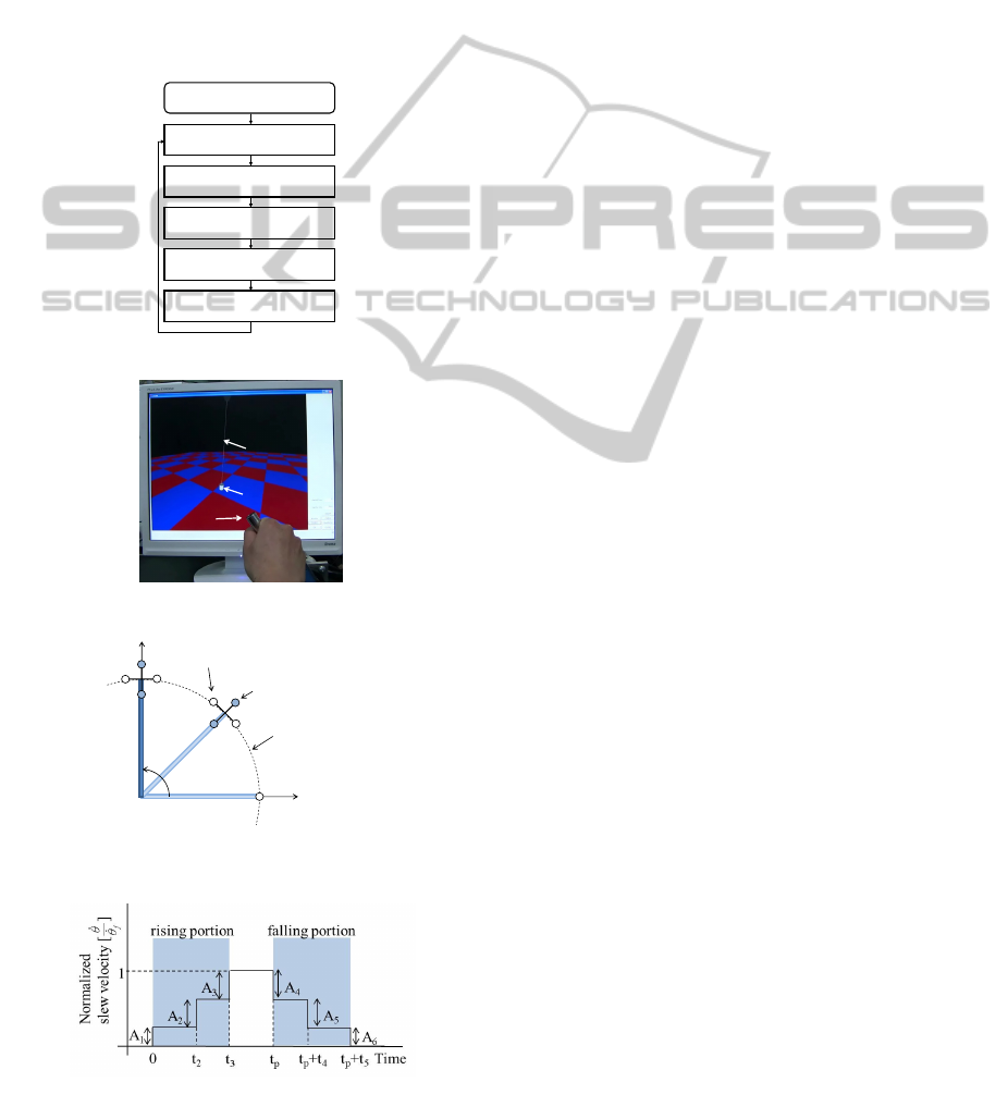
3 CONSTRUCTION OF VIRTUAL
SIMULATOR
In this section, a virtual crane simulator using crane
model is built. The present visual simulator consists
of displayed graphics of crane boom and load, and
joystick displayed graphics for operation. The
graphics on computer display is created using Open
GL. Operational view of this simulator configures
from a cockpit of a crane, and translates its view
position with slew motion of crane cockpit.
Operational interface (device) for virtual simulator
uses Active Joystick (will be explained later). Flow
of this simulator is shown in Figure 3. First, read
velocity input from Active Joystick. Second, it
calculates operational amounts of rotary, Boom
hoisting, and load hoisting from velocity input.
Thirdly, it calculates the states of Boom tip and load
using crane model. Finally, it makes a static graphic
of a crane, and renders its graphics at 30 [msec]
intervals. By repeating this flow, it is displayed
crane graphic naturally on real-time. Figure 4 shows
virtual crane simulator built with Active Joystick.
4 DERIVATION OF SWAY
SUPPRESSION CONTROL
INPUT
The load sway of a rotary crane is affected by
acceleration or deceleration of the boom and
centrifugal force, because the boom is rotated. Thus,
load sway becomes two-dimensional sway
consisting of radius direction sway and slew
direction sway (see Figure 5). Additionally, in the
case that the boom rotates 90 degrees, the slew
direction sway mutates into the radius direction
sway from initial position to target position in
absolute coordinates.
Given these facts, we use the 2-Mode Input
Shaping method by Shighose et al. (Jason et al.,
2010), in which velocity variation changes in three
steps for the anti-sway. Because the Input shaping
control method is very intuitive one, it is considered
that it is easier for operators to train the anti-sway
control input compared with other methods (see
Figure 6). The optimal velocity A
i
[rad/s] and the
timing of velocity variation t
i
[s] are derived to
minimize residual sway. This method can control the
residual radius direction sway and slew direction
sway by only rotary actuator. Time t
p
[s] is the
arbitrary time at which the crane is commanded to
begin decelerating. The vertical axis is normalized
by the final setpoint slew velocity
f
[rad/s]
yielding
1
321
AAA
(5)
1
654
AAA
(6)
This means that only amplitudes A
1
, A
2
, A
4
, and A
5
need to be derived since A
3
and A
6
can be found
directly from Equation (5) and (6).
The relational expression of slew velocity and
sway angle becomes Equation (7).
START
Read input from Active Joystik
Calculate the rotary, Boom-hoisting,
and load-hoisting amount
Calculate the crane and load position
Draw a static graphic
Render static graphic
at 30[ms] intervals
Fi
g
ure 3: Flow of simulator.
X
Y
Boom tip trajectory
Boom rotation
Slew direction sway
Radius direction sway
Figure 5: Characteristics of load sway for a rotary
crane.
Figure 6: 2-Mode Input Shaping command template.
Load
Rope
Active
Joystick
Figure 4: Visual crane simulator.
ICINCO2013-10thInternationalConferenceonInformaticsinControl,AutomationandRobotics
60
020
1000
200
1010
2
0
2
2
0
2
(7)
Here, α and β have high-frequency modes and low-
frequency modes respectively from characteristic
value of state equation. Here, the sum of high-
frequency modes defines v
jk
[rad], and the sum of
low-frequency modes defines y
jk
[rad],
0
[rad/s] is
natural frequency. These modes can be expressed by
Equation (8) and (9):
jj
kj
j
k
k
B
jk
l
L
v
1
2
0
0
(8)
jj
kj
j
k
k
B
jk
l
L
y
1
2
0
0
(9)
where,
kkjj
kkjj
00
00
,
,,
Here
B
L
=17.5[ml], l = 20[m],
j
is slew velocity
before input A
i,
j
is slew velocity before input A
i
,
j
[rad/s] and
j
[rad/s] are the high and low modes at
f
respectively, while
k
[rad/s] and
k
[rad/s] are
the high and low modes at
k
, respectively. By
recursively applying Equation (8) and (9) to the
command template in Figure 6, the complex valued
residual sway of two modes,
v
tot
[rad] and
y
tot
[rad]
can be derived as follow:
231201
23223221
vevevv
ttittti
tot
(10)
231201
23223221
yeyeyy
ttittti
tot
(11)
Where
v
tot
and
y
tot
are found from Eps. (8) and (9)
(Equation (5) - (11) details; see the original papers
of Singhose, et al. (David, 2002).) These terms are
the change in the complex amplitudes of first and
second caused by a step transition from
f
to
k
,
fff
AAA
3212110
,,,0
(12)
where A
1
, A
2
, t
2
, and t
3
refer to the step amplitudes
and times shown in Figure 6.
In rising portion (acceleration interval), it needs
to derive A
1
, A
2
, t
2
, and t
3
such that v
tot
and y
tot
are
minimized. Similarly, it needs to derive A
4
, A
5
, t
4
,
and t
5
in falling portion (deceleration interval). This
study minimizes using conjugate gradient method,
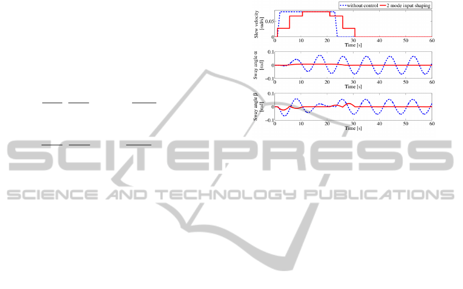
and run a simulation. By simulation result in Figure
7, it was able to confirm that 2-Mode Input Shaping
reduce residual sway of the load. And that, the
timing of changing velocity in second step and third
step was turn out when the sway angle and a crane
become vertical.
Figure 7: Simulation result for 2-Mode Input Shaping.
5 PROPOSED LEARNING
ASSIST SYSTEM
Instructors verbally explain the sway suppression
techniques at the crane driving school. Beginners
receive the explanation, and then practice crane
operation by themselves. However, this training
method will be not the sufficient training for
beginners. In this section, using the 2-Mode Input
Shaping method described in the previous section, a
novel training system for beginners that teaches the
amount and timing of acceleration or deceleration is
presented. By teaching these operational skills, we
hope that the training effect will be enhanced and the
training period shortened for beginners. So, we
propose the training system by giving sensory
information of humans such as ideal operation of
joystick or visual information. In this paper, two
methods of teaching operational skills are proposed.
One is ideal operation of joystick guidance training
by presenting ideal operation of joystick information,
and the other is visual guidance training by
presenting visual information.
One training method we propose is often used in
sports training and skills education. Such training
through hands-on coaching is known to be effective
in many situations. This study focused attention on
this point, and proposes ideal operation of joystick
guidance training by the joystick of operational
interface for obtaining the sway suppression skill.
Principle of this learning method is as follows.
Namely, active joystick interface is automatically
moved by using inverse kinematics of motor model
NovelVirtualTrainingSystemtoLearntheSwaySuppressionofRotaryCranebyPresentingIdealOperationofJoystickor
VisualInformation
61
from anti-sway reference velocity obtained from 2-
Mode Input Shaping method. Then, beginners are
able to learn a sense of the skill by touching its
joystick with his or her hand and feeling the motion.
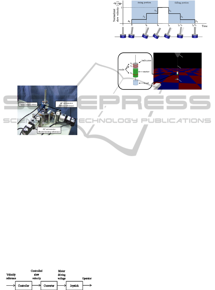
Figure 8 shows the Active Joystick that is the
operational interface used in this study. This joystick
is equipped with a 6-axis force sensor and AC servo
motors. The joystick rotates on the X
J
-axis and Y
J
-
axis. If the joystick is tilted on X
J
-axis, it rotates the
rotary crane, and if it is tilted on Y
J
-axis, the boom is
hoisted. In order to drive the joystick, 2 AC servo
motors with harmonic drive (speed reduction ratio =
1:100) are utilized. A force/torque sensor is attached
on the joystick to measure the force that the operator
applies to the joystick.
Figure 8: Active Joystick.
Furthermore, the joystick incorporates a spring mass
damper model so that an operator can move the
joystick using relatively little force and when the
operator removes his hand from the joystick, the
joystick automatically returns to its starting point.
The joystick's motion equation is expressed as
follows:
yJrJrJr
MkdJ
(13)
where,
J
: joystick's inclination angle from original
point, M
y
: force applied on joystick by operator, J
r
=
0.1[kgm
2
]: inertia moment, d
r
= 0.7 [Nms/rad]:
viscous friction coefficient, and k
r
= 1.65 [N/m]:
spring constant.
Figure 9 shows outline of learning assist system.
This system converts the sway suppression control
input into driving voltage of motors, and replicates
its input by its joystick. Beginners can learn to the
sway suppression skill sensuously, because they feel
maneuvering feeling like getting coaching from
expert. Thus, they will be able to achieve its
Figure 9: Diagram of haptic guidance.
Figure 10: Motion of Active Joystick for each time.
Boom
Load
Virtual Simulator Display
Rope
Boom
Load
Virtual Simulator Display
Rope
Figure 11: Indicator for visual guidance.
operational amount and the timing by using this
training (see Figure 10).
The other training method that we propose is
visual guidance training involving the presentation
of visual information. An indicator is displayed on
the screen of the crane simulator shown in Figure 11.
This indicator shows the amount of acceleration or
deceleration A
i
on a three-step scale for control of
the load sway. The height of the meter changes in
proportion to joystick angle. Thus, beginners will be
able to learn the amount and timing of acceleration
or deceleration required by spontaneously
manipulating the joystick in accordance with the
scale.
6 RESULTS OF VIRTUAL
TRAINING EXPERIMENTS
AND DISCUSSION
The effectiveness of the proposed novel learning
assist system was evaluated by means of an
experiment. In this experiment, training was
conducted for 13 men who had no experience of
crane operation. The subjects were divided into the
following four groups:
Group A: 2 men, self-training, without oral
presentation
Group B: 3 men, self-training, with oral
presentation
Group C: 4 men, ideal operation guidance
training
Group D: 4 men, visual guidance training.
Before starting the experiment, the sway suppression
skill was explained verbally to each group,
ICINCO2013-10thInternationalConferenceonInformaticsinControl,AutomationandRobotics
62
excluding Group A. Using the crane simulator that
we developed, each group transports a load
(height:0.9[m], radius:0.3[m]) several times. Each
group transports the load to a circular target position
(radius: 0.4[m]) by turning the rotary crane 100[deg].
For automatic transportation using 2-Mode Input
Shaping, transfer time is 29.6[s]. However, for
transportation by manual operation, it is almost
certain that human error will occur. Thus, in
consideration of human error, transfer time is set to
within 35.0[s]. Parameters of the rotary crane
simulator are listed in Table 1, and parameters of 2-
Mode Input Shaping shown in Table 2.
Table 1 : Parameter of rotary crane for training use.
Parameter Symbol Value Units
Rope length l 20.0 m
Boom length L
B
17.5 m
Boom hoisting angle
45.0 deg
Max slew velocity
0.08 rad/s
Table 2: Parameters of 2-Mode Input Shaping.
A
1
A
2
t
2
t
3
0.3442 0.4902 4.6476 9.5657
A
4
A
5
t
4
t
5
0.1673 0.4912 4.9161 9.5701
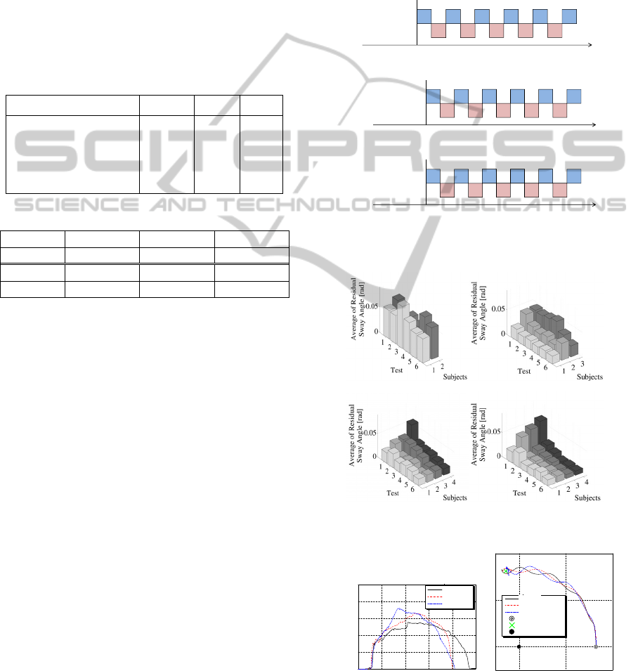
The training schedule is shown in Figure 12. First,
subjects of each group transport the load three times
without assistance, and then they transport the load
three times with assistance. This flow is treated as
one set, and this set is conducted five times. Finally,
one set is conducted again without assistance, and
residual sway of all test sets is evaluated. Training
time of one set is about 3 minutes, all training time
is about 40 minutes with break time.
The learning effect is evaluated on the basis of
residual sway. Figure 13 shows the average residual
sway angle for trials of each group. Figure 13 (a)
shows that subjects in Group A were unsure about
the crane operation because they were not given
information about it. Figure 13 (b) shows that the
average residual sway angle for Group B was on a
modest declining trend. However, because subjects
in Group B were not informed of the amount and
timing of acceleration or deceleration required, they
had to ascertain it by trial and error. Therefore, the
training effect for Group A and Group B was low.
Figure 13(c) shows that the average residual sway
angle for Group C steeply trended downward. As the
subjects in Group C were able to experience the
ideal sway suppression skill through ideal operation
guidance, they were able to replicate it well.
Therefore, we conclude that the ideal operation
guidance training is effective. However, as shown in
Figure 13 (d) Group D’s results were superior to
those of the other groups, which is considered to be
attributable to the superior effect of visual guidance
training because it allows the subjects to recognize
the disparity between actual and ideal input and
rectify it by spontaneous joystick operation in real
time.
3self training
test
3 3
3
3
3
3
3
3
3
3
Trials
(a) Group A and Group B
3
ideal operation
guidance training
test
3 3
3
3
3
3
3
3
3
3
Trials
(b) Group C
3
Visual
guidance training
test
3 3
3
3
3
3
3
3
3
3
Trials
(D) Group D
Figure 12: Training schedule for each group.
(a) Group A (b) Group B
(c) Group C (d) Group D
Figure 13: Training result for each group.
Figure 14: Training result of 6th test by certain subject in
Gourp A.
0 10 20
0
10
20
X [m]
Y [m]
1st Trial
2nd Trial
3rd Trial
Start position
Target position
Axis o f rotation
1st Trial
2nd Trial
3rd Trial
St art posit ion
Target position
Axis of rotation
10 20 30 40 50
0.02
0.04
0.06
0.08
0.1
0
Time [sec]
slew velocity [rad/s]
1st Traial
2nd Traial
3rd Traial
1st Traial
2nd Traial
3rd Traial
(a) Slew velocity input
(b) Load trajectory
NovelVirtualTrainingSystemtoLearntheSwaySuppressionofRotaryCranebyPresentingIdealOperationofJoystickor
VisualInformation
63
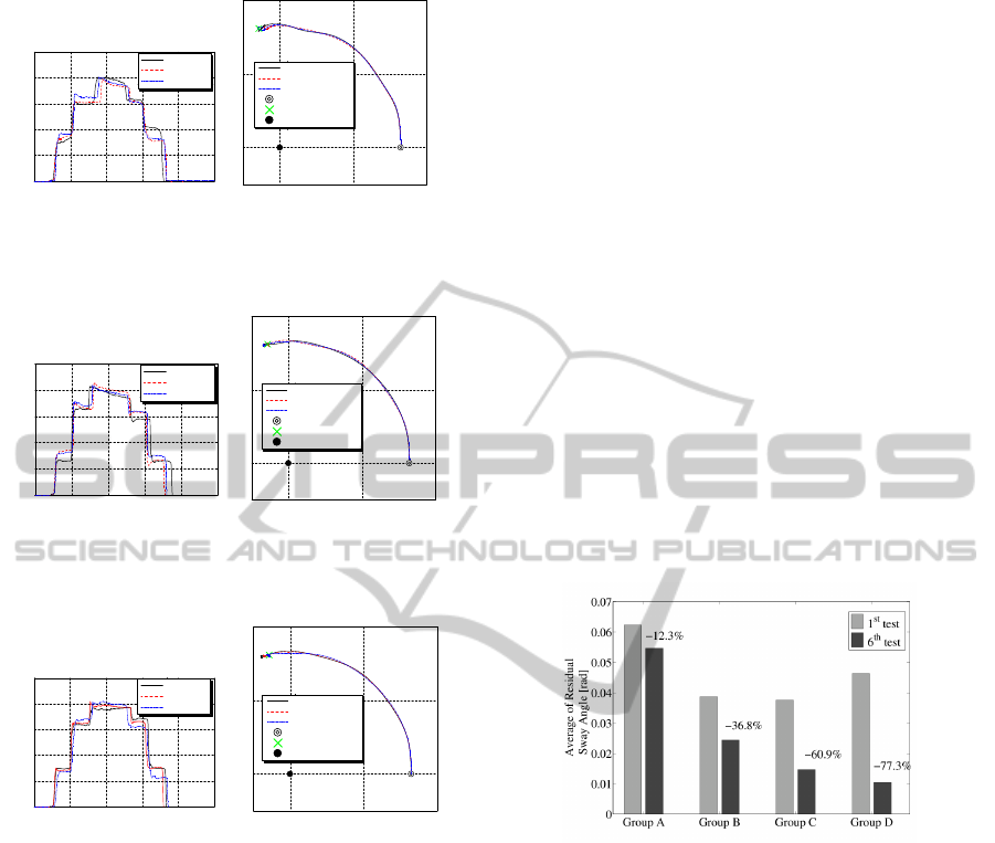
Figure 15: Training result of 6th test by certain subject in
Gourp B.
Figure 16: Training result of 6th test by certain subject in
Gourp C.
Figure 17: Training result of 6th test by certain subject in
Gourp D.
Figure 14 through Figure 17 shows the slew velocity
input and the load trajectory of the 6th test involving
certain subjects of each group. Slew velocity of
Group D is reproduced stably three times and load
trajectory is comparatively smooth. Figure 18 shows
the diminishing rate of residual sway by comparing
the results of the first test with those of the final test.
As can be seen from these results, the learning assist
system will shorten the training period for beginner
crane operators. In addition, the efficiency of work
will increase because of a decrease in residual sway.
Furthermore, we conducted simulation
experiments for various lope length such as l=15[m],
25[m] and l=30[m]. In any cases, we obtained the
results of learning effects as almost same as the
results of l=20[m] if we learn how to operate for
anti-sway by using 2-Mode Input Shaping method
for each order rope length. We omitted the results
due to the limitation to validate the proposed method
in real processes. We will show the results in the
presentation of ICINCO 2013 conference. We can
learn the skill for various rope length of l=20-
100[m] so long as we learn how to operate for the
rope length of l=20[m] and l=100[m] at both ends.
Now, an alternative method as training way will
be discussed here. A way to present ideal
movements of joystick proposed in this paper can
certainly teach the motion of joystick, but not the
force to push joystick. After learning how to move
the joystick without force information, operator must
operate joystick by grasping it. Then, operator
needs not only motion, but also force reference
information. Therefore, through the results of this
study, a learning system is expected such that ideal
force for anti-sway is memorized in computer, and a
haptic feedback is worked against operator’s actual
force input. Furthermore, a hybrid training system
constructed of haptic feedback and visual indicator
proposed in this paper may be better. We will also
present them in near future.
Figure 18: Comparasion of residual sway before and after
training for each group.
7 CONCLUSIONS
In this study, we built a virtual crane training
simulator such as presenting sway suppression skill.
The results are as follows.
1. A crane training simulator using rotary crane
model has been built.
2. As operational interface for simulator, Active
Joystick presenting ideal operation of joystick
information is developed.
3. The sway suppression control using 2-Mode
Input Shaping method is applied in this study,
and sway suppression is well achieved.
4. Guidance training methods by presenting ideal
operational joystick or visual information are
proposed.
0 10 20
0
10
20
X [m]
Y [m]
1st Trial
2nd Trial
3rd Trial
Start position
Target position
Axis of rotation
1st Trial
2nd Trial
3rd Trial
Start position
Target position
Axis of rotation
10 20 30 40 50
0.02
0.04
0.06
0.08
0.1
0
Time [sec]
slew velocity [rad/s]
1st Traial
2nd Traial
3rd Traial
1st Traial
2nd Traial
3rd Traial
(a) Slew velocity input
(b) Load trajectory
0 10 20
0
10
20
X [m]
Y [m]
1st Trial
2nd Trial
3rd Trial
Start position
Target position
Axis o f rotation
1st Trial
2nd Trial
3rd Trial
Start position
Target position
Axis of rotation
10 20 30 40 50
0.02
0.04
0.06
0.08
0.1
0
Time [sec]
slew velocity [rad/s]
1st Traial
2nd Traial
3rd Traial
1st Traial
2nd Traial
3rd Traial
(a) Slew velocity input
(
b
)
Load tra
j
ector
y
10 20 30 40 50
0.02
0.04
0.06
0.08
0.1
0
Time [sec]
slew velocity [rad/s]
1st Traial
2nd Traial
3rd Traial
1st Traial
2nd Traial
3rd Traial
(a) Slew velocity input
0 10 20
0
10
20
X [m]
Y [m]
1st Trial
2nd Trial
3rd Trial
St art position
Target position
Axis of rotation
1st Trial
2nd Trial
3rd Trial
Start pos ition
Target position
Axis of rotation
(b) Load trajectory
ICINCO2013-10thInternationalConferenceonInformaticsinControl,AutomationandRobotics
64

5. It was clear that visual guidance training
decreased 77% of residual sway than
conventional training in the same training time
through many simulation experiments.
As future work, we apply this result to real
experimental apparatus. Furthermore, we plan to
extend to shipboard crane with the present training
function. The operation of shipboard crane is highly
required to get operational skill, because crane
operator must consider complicated ship sway in
addition to anti-sway on boom and load of crane.
REFERENCES
Jiung, Y., Huang, Chung, Yun, G., 2003. Modelling and
Designing a Low-Cost Hight-Fidelity Mobile Crane
Simulator, Int. Journal of Human-Computer Studies,
Vol.58, No.2, pp.151-176.
Mohammed, F., Daqaq, Ali, H., Nayfeh, 2003. Virtual
Reality Simulation of Ships and Ship-Mounted Cranes,
Master thesis, Virginia Polytechnic Institude and State
University.
T., Iwasa, K., Terashima, N.Y. Jian, Y., Noda, 2010.
Operator Assistance System of Rotary Crane by Gain-
scheduled H-inf Controller with Reference Governor,
2010 IEEE International Conference on Control
Applications (CCA), Yokohama, Japan, September 8-
10, [1325-1330].
N., Yong, Jian, Y., Noda, K., Terashima, 2011. Simulator
Building for Agile Control Design of Shipboard Crane
and its application to Operational Training, 18th
World Congress of the International Federation of
Automatic Control (IFAC), Universita Cattolica del
Sacro Cuore, Milano.
Y., Shen, K., Terashima, K., Yano, 2003. Optimal Control
of Rotary Crane Using Straight Transfer
Transformation Method to Eliminate residual
Vibration, Trans. of the Society of Instrument and
Control Engineers, vol.39, No.8, [817-826].
Jason, Lawrence, William, Singhose, 2010. Command
Shaping Slewing Motions for Tower Crane, Journal of
Vibration and Acoustics, Vol. 132, No.1.
David Feygin, Madeleine Keehner, Frank Tendick, 2002.
Haptic Guidance: Experimental Evaluation of a
Haptic Training Mathod for a Perceptual Motor Skill,
Proceeding of the 10th Int. Symposium on Haptic
Interfaces for Virtual Environment and Teleoperator
Systems, pp,40-47.
Dan Morris, Hong Tan, Federico Barbagli, Timothy
Chang, Kenneth Salisbury, 2007. Haptic Feedback
Enhances Force Skill Learning, Symposium on Haptic
Interfaces for Virtual Environment and Teleoperator
Systems, pp.21-26.
M. Al-Hussein, M.A. Niaz, H. Yu, H. Kim, 2006.
Integrating 3D visualization and simulationnext term
for tower previous termcranenext term operations on
construction sites, Automation in Construction, Vol.
15, no. 5, pp. 554-562.
A. Khalid, J. Huey, W. Singhose, J. Lawrance, D. Frakes,
2006. Human Operator Performance Testing Using an
Input-Shaped Bridge Crane", Journal of Dynamic
Systems Measurement and Control, Vol.128, No.4,
pp.835-841.
R. B. Gillespie, S.O'Modhrain, P.Tang, C.Pham,
D.Zaretsky, 1998. The Virtual Teacher, ASME
International Mechanical Engineering Conference and
Exposition.
J.Bluteau, S.Coquillart, Y.Payan, E.Gentaz, 2008. Haptic
guidance improves the visuo-manual tracking of
trajectories, PLos ONE 3, Vol.3.
D. Feygin, M. Keehner, F. Tendick, 2002. Haptic
Guidance: Experimental evaluation of a haptic
training method for a perceptual motor skill,
Proceedings of the 10th Symposium on Haptic
Interfaces for Virtual Environment and Teleoperator
Systems, pp. 40-47.
K. Terashima, Y. Shen, K. Yano, 2007. Modeling and
optimal control of a rotary crane using the straight
transfer transformation method, Int. J. of Control
Engineering Practice 15, Elsevier, pp. 1179-1192.
Y. Shen, K. Terashima, K. Yano, 2004. Minimum time
control of a rotary crane using straight transfer
transformation method, Transactions of the Society of
Instrument and Control Engineers, Vol. 3, No. 10, pp.
70-79.
Y. Shen, K. Terashima, K. Yano, 2001. Starting control
with vibration damping by hybrid shaped approach
considering time and frequency specifications,
Transactions of the Society of Instrument and Control
Engineers, Vol. 137, pp. 403-410.
NovelVirtualTrainingSystemtoLearntheSwaySuppressionofRotaryCranebyPresentingIdealOperationofJoystickor
VisualInformation
65
