
Extending OCL to Specify and Validate Integrity Constraints
in UML-GeoFrame Conceptual Data Model
Angélica Ap. de A. Ribeiro
1,2
, Sergio M. Stempliuc
2
, Jugurta Lisboa-Filho
1
and Italo Lopes Oliveira
2
1
Departamento de Informática, Universidade Federal de Viçosa (UFV), Viçosa, MG, Brazil
2
Faculdade Governador Ozanam Coelho (Fagoc), Ubá, MG, Brazil
Keywords: OCL, UML-GeoFrame, Geographical Databases.
Abstract: This paper describes a proposal for OCL (Object Constraint Language) by adding geographical features to
assist the geographical data modeling. OCL can be used to complement the diagrams when the UML
constructors do not allow the specification of all requirements related to the application domain.
The objective is to complement and validate conceptual data diagrams built with constructors of the
UML-GeoFrame data model, with and extended OCL used for constraint topological relationships in the
data model itself and available in his diagram to access stereotypes for direct user defined constraints.
1 INTRODUCTION
The Unified Modeling Language (UML)
(OMG, 2011) has a great acceptance as a language
for modeling and designing software systems.
However, the UML diagrams are not capable of
including all its needs, thus requiring a mechanism
so that the specific domain constraints can be
documented in the modeling stage, named Object
Constraint Language – OCL (Warmer and Kleppe,
2003); (OMG, 2012).
The OCL arises as a proposal to help in the
declaration of these constraints, still in the process of
conceptual modeling, ensuring that the modeling is
done in order to produce diagrams without
ambiguities, providing a higher quality stored data.
According to Lisboa Filho and Stempliuc (2009),
many integrity constraints cannot be directly
expressed in the conceptual database modeling and
are imposed by the application so that the stored data
do not violate the rules established during the
requirements phase.
As in conventional databases, in geographical
databases it is not possible to use only UML
diagrams to represent the integrity constraints that
determine the aimed data quality. However, unlike
conventional databases, OCL does not have enough
operators to declare constraints considering the
details of the geographical elements.
The objective of this paper is to proceed the
propositions of existent extensions to the OCL
constructors, as presented in Duboisset et al. (2005),
that help the declaration of integrity constraints in
the geographical database modeling. Thus, the
proposed extension’s main objective is to
complement the diagrams built using the UML-
GeoFrame with the aid of an extended OCL
expression. UML-GeoFrame is a conceptual data
model that uses class diagrams from UML to extend
the GeoFrame framework. Details about this model
can be found in Lisboa Filho and Stempliuc (2009).
The remainder of the article is structured as
follows. Section 2 describes the types of geometrical
relationships involving points, lines and polygons
elements proposed by Clementini et al., (1993).
Section 3 presents a proposal to extend the OCL
language, showing how it can be used to help in the
modeling of geographical data. Section 4 shows an
example of how to use the proposed OCL
expression. Section 5 presents the final
considerations and future works.
2 RELATIONSHIP BETWEEN
GEOMETRICAL TYPES
As geographic elements are represented through the
geometrical types Point, Line and Polygon,
Clementini et al., (1993) propose an extended model
to the 4-intersection matrix proposed by Egenhofer
286
Ap. de A. Ribeiro A., M. Stempliuc S., Lisboa-Filho J. and Lopes Oliveira I..
Extending OCL to Specify and Validate Integrity Constraints in UML-GeoFrame Conceptual Data Model.
DOI: 10.5220/0004451502860293
In Proceedings of the 15th International Conference on Enterprise Information Systems (ICEIS-2013), pages 286-293
ISBN: 978-989-8565-60-0
Copyright
c
2013 SCITEPRESS (Science and Technology Publications, Lda.)

and Franzosa (1991) in order to include information
about the intersection dimension, as the largest
resulting value of the intersection between two
spatial objects. The resulting dimension of the two-
dimensional intersection can be: empty (Ø), 0D
(point), 1D (line) and 2D (area or polygon).
The interior and boundary are used in the method
to describe the topological relationships existing
between the interior and boundary of a spatial
object. Clementini et al., (1993) shows the geometric
elements having the following characteristics:
∂P: The limit of a point is always empty;
∂L: The limit of a line are two points of its end;
∂A: The limit of an area is a closed line.
The interior of a point is the own point and of a
circular line is the own line.
The interior of a geometrical element is denoted
by λ° = λ - ∂λ, where the symbol λ represents a
geographic type, the symbol ∂λ represents its
boundary and the symbol λ° represents its interior.
Table 1 illustrates the resulting sets between the
interiors and boundaries of the Point, Line and
Polygon (area) types. There are four possible
combinations between the interior and the boundary
of a geometrical element: S1 = ∂λ1 ∩ ∂λ2,
S2 = ∂λ1 ∩ λ2°, S3 = λ1° ∩ ∂λ2 and S4 = λ1° ∩ λ2°.
The first and second operands of the intersections
are associated to the first and second elements from
the geometric type column present in Table 1.
Table 1: Dimension information about the intersection of
the geometric elements.
_______________________________________________
Geometric Type S
1
S
2
S
3
S
4
_______________________________________________
Point and Point Ø Ø Ø
Ø,0D
Point and Line Ø Ø Ø,0D Ø,0D
Point and Area Ø Ø Ø,0D Ø,0D
Line and Area Ø,0D Ø,0D Ø,0D,1D Ø,1D
Line and Line Ø,0D Ø,0D Ø,0D Ø,0D,1D
Area and Area Ø,0D,1D Ø,1D Ø,1D Ø,2D
______________________________________________
A relationship involving two geometrical types
can be considered possible or real. A possible
relationship is a specific combination between the
dimensions of the geometrical elements involved,
but it is not possible to represent it in the real world.
On the other hand, a real relationship is a possible
combination and can exist in the real world.
An example of a possible relationship is when a
point must be inside an area and touches its
boundary at the same time. Because the 0D nature of
the point, it would not really be possible to establish
this relation.
However, a combination that establishes only
that the point must be inside the area, besides being
a possible combination is commonly used by the
SIG community.
The real relationships involving the geometrical
types of Table 1 are (Clementini et al., 1993):
Point and Point: disjoint and in;
Point and Line: disjoint, touch and in;
Point e Area: disjoint, touch and in;
Line and Area: disjoint, touch, in and cross;
Line and Line: disjoint, touch, in, cross and
overlap;
Area e Area: disjoint, touch, in, overlap, equal
e cover.
Table 2 complements the relationships between
the geometrical types inverting the order of the
operands. Comparing Table 1 with Table 2, it is
possible to note that the cases are symmetrical and
very similar, but not equal. Where the intersection
involves the point element, such as the Area/Point
and Line/Point, the intersections S
2
and S
3
of Table 2
will be different from the result found in Table 1, as
the point has no boundary, and in all cases that the
intersection about the point boundary is being
verified, like in S
3
, its intersection size will be empty
(
Ø). Other similar cases happen with the relationship
Area/Line, where the relationship Line/Area will be
different only in intersections S
2
and S
3
.
Table 2: Dimension information from the intersection of
elements that possess symmetric cases
______________________________________________
Geometric Type S
1
S
2
S
3
S
4
______________________________________________
Line/Point Ø Ø,0D Ø Ø,0D
Area/Point Ø Ø, 0D Ø Ø,0D
Area/Line Ø,0D Ø,0D,1D Ø,0D Ø,1D
______________________________________________
The real relationships involving the geometrical
types of Table 2 are:
Line and Point: disjoint, touch and crosses;
Area and Point: disjoint and touch;
Area and Line: disjoint, touch and crosses.
3 EXTENDING OCL FOR
TOPOLOGICAL RELATIONS
The written expressions in the OCL are not
ambiguous and add vital information for the object-
oriented model and other modeling artifacts
ExtendingOCLtoSpecifyandValidateIntegrityConstraintsinUML-GeoFrameConceptualDataModel
287

(Warmer and Kleppe, 2003). Also according to the
authors a lot of failures from diagrams are caused by
limitations of the models which cannot express all
data requirements of the complete application
specification. Due to the fact that natural language
lead to ambiguities during its interpretation process
by different persons, the OCL proposes to
complement the UML diagrams in an accurate and
not ambiguous way, creating a more complete and
satisfactory specification of the problem.
Duboisset et al., (2005) propose OCL
expressions involving the relationship between
areas, based in 8 topological relationships that are
described in Egenhofer and Franzosa (1991). The
extension proposed in this article is based in
Duboisset et al., (2005), but extended to the
topological relationships between point, line and
polygon of section 2.
3.1 Validating the Topological
Relationships on UML-GeoFrame
In the UML-GeoFrame data model, the geographic
phenomena are modeled by classes with stereotypes
of spatial representation corresponding to the
symbols that can characterize its geometrical
representation. A class of phenomenon in the object
view can have a geometrical representation of type
point (), line () or polygon (). A class can have
multiple representations. This property can be used,
for example, when an object can be stored as point
and area, according to the scale of the application.
In addition to the phenomenon from the object
view, there is a lot of phenomenon in the field view
that can have a geometrical representation of grid
cells (), grid of points (), adjacent polygons
(),isolines () and irregular points () types.
Based in the characteristics of the field view
presented by Lisboa Filho et al. (1996), the
topological constraints presented in section 2 do not
apply, thereby this article will treat only the existent
relationships in the object view.
Textual stereotypes (<<stereotypes>>) are used
in the UML-GeoFrame diagrams to specify existing
topological relationships between the geographical
phenomenon classes, allowing the designer to have a
better understanding of the diagram. However, the
use of textual stereotypes itself may not make clear
the topological relationship between the involved
classes, since it contains no mechanism to indicate
the order in which its reading can be realized.
A possible solution to the problem referring to
the interpretation of topological relationships is to
use existing arrows of the UML. According to
Dietrich and Urban (2005), an arrow can be used to
indicate how the reading of the associations between
the classes can be made.
However, even with the use of arrows to indicate
a direction to read and the use of textual stereotypes
to indicate spatial constraints between two classes, a
less experienced designer could model the
topological relationships in the incorrect form. For
example, when modeling two distinct classes
represented by the geometric type Point, the
designer could specify the relationship “touch”
although this type of relationship does not exist
between the types Point and Point. The model alone
cannot avoid that errors like this can be added in the
conceptual modeling phase. Therefore, this paper
proposes constraints using OCL defined about the
own UML-GeoFrame to verify if relationships
specified in diagrams are valid. Constraints are
specified using the syntax in Code 1:
Code 1: OCL syntax for the UML-GeoFrame validation.
context Class1
inv: self.geometry.OclIsKindOf(geometricType)
inv: Class2.geometry.OclIsKindOf(geometricType)
inv: self.stereotype = PossibleRelationTypes
The proposed OCL expression, with the intention
of validating the UML-GeoFrame diagram, uses
syntax constructors from the standard OCL. These
constructors are reserved words, like Context, that
informs the class to which the OCL expression is
related, specifying an entity defined in the UML
diagram. It also possesses invariants (inv) that are
boolean expressions, which define rules that must
always be satisfied by all instances of defined type.
The reserved word self is optional and used to
explicitly refer to an instance that was specified in
context. For example, in the expression in Code 1,
self refers to an instance of Class1.
Besides the reserved words used in the OCL
standard, the OCL expression presented in Code 1
extends the OCL by adding geographical
constructors to help the validation of the diagram
build using the UML-GeoFrame conceptual data
model. Therefore, the reserved word geometry is
added to the OCL and together with the existing
reserved word OCLIsKindOf, verifies whether the
modeled classes are of point, line or polygon type.
OCLIsKindOf is used to verify if the declared type is
equal to the one restrained in the context class.
This notation of the OCL expression proposed in
Code 1 is used with the purpose of verifying if the
relationship involving the classes are valid, thus
avoiding errors during the modeling and the
ICEIS2013-15thInternationalConferenceonEnterpriseInformationSystems
288
subsequent errors during data insertion. The
relationships will be valid if they obey what is
described in the invariants, when both return true.
An example of this validation through this syntax is
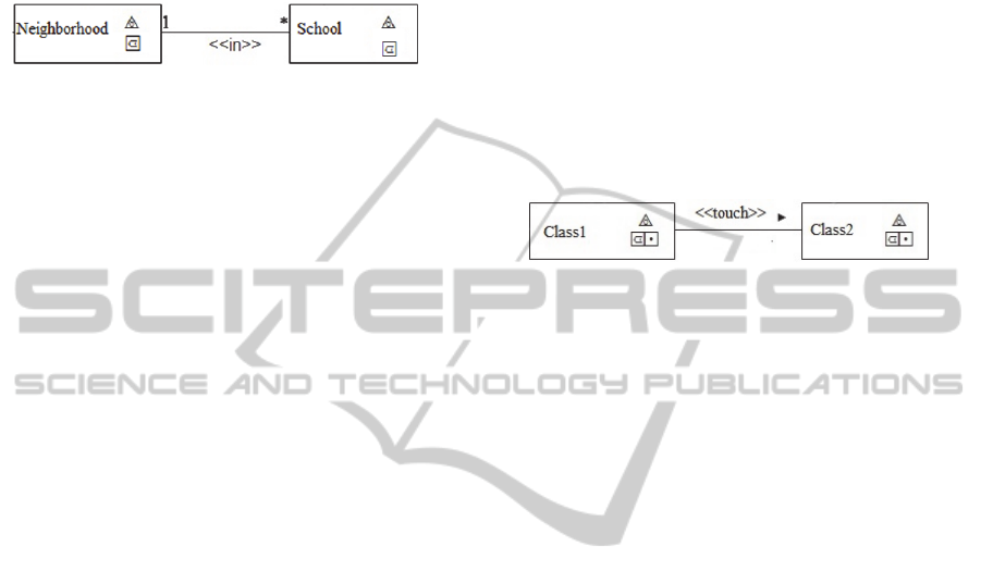
in Code 2 to the diagram of Figure 1, which defines
that one school must be inside a neighborhood.
Figure 1: Representation of the Textual Stereotype.
Code 2: Validation of the diagram presented in Figure 1.
context School
inv: self.geometry.OclIsKindOf(area)
inv: Neighborhood.geometry.OclIsKindOf(area)
inv: self.stereotype = ‘in’
or self.stereotype = ‘touch’
or self.stereotype = ‘overlap’
or self.stereotype = ‘equal’
or self.stereotype = ‘contains’
or self.stereotype = ‘disjoint’
The first invariant validate the geometricType of
the context class (School). This verification is made
through the expression OCLIsKindOf. The same is
done to Class2 (Neighborhood) in second invariant,
which represents the class to which the context is
associated. The third invariant is verified and returns
true if the textual stereotype that represent the
topological relationship between the two classes
involved is equal to one of the possible types
between the same two geometrical elements
presented in section 2. Besides, the keyword
stereotype is a characteristic of the relationship that
involves the School and Neighborhood classes, and
it can be accessed from both. The use of
self.stereotype helps understanding the relationship
reading, indicating that a school must be inside a
neighborhood and not the opposite.
3.2 Extending the OCL to use with
UML-GeoFrame Diagrams
When the classes that are being modeled possess
only one geographical stereotype to represent the
geometrical element, the relationships between the
existing classes can only be presented through the
textual stereotypes, thus no requiring an OCL
expression to complete the meaning of the diagram,
but only to verify if the relationship between the
classes is valid, once only the textual stereotypes and
the arrows to read the relationship would make the
diagram comprehensible.
For two classes with multiple geometrical
representations have a valid relationship between
then according to the real relationships shown in
section 2, all pairs of geometrical types of the
classes must be valid and there is no need to use an
OCL expression to complement the diagram.
However, if a topological relationship is invalid
between at least one pair of geometries it will be
necessary to use an OCL expression to complete the
diagram and show the geometries that will be
involved in the topological relationship. If the
topological relationship is not valid for any pair of
the involved geometries, the designer must evaluate
the relationship as it may have been modeled
incorrectly. Figure 2 shows an example involving
classes with multiple representations.
Figure 2: Using multiple representations.
Figure 2 shows two hypothetical geographical
phenomena, modeled as Class1 and Class2, both
represented by the geographical stereotypes Point
and Polygon (Area). The topological relationship
involving these two classes is the relationship touch.
Analyzing the possible relationships between Class1
and Class2 and considering the touch relationship
between the geometrical elements Area and Area or
even between Point and Area, this relationship will
be considered valid. However, when considering the
geometric type Point in both classes, the relationship
touch violates the topological constraint, as there is
no such relationship between two points.
Therefore, most times when a relationship occurs
between two classes that contain multiple
geometrical representations, only the use of textual
stereotypes is not capable of expressing correctly in
the diagram a correct topological relationship
without ambiguities. Therefore the OCL should be
used to assist this process, showing which
geometries are in fact involved in the expressed
relationship within the diagram. Code 3 presents the
proposed syntax so the designer could specify
integrity constraints involving the geometries of the
classes and topological relationships between them.
Code 3: OCL expression for topological relationships.
context <GeoClass1>
inv: <GeoClass1>.<geometry>.<relationship>.
<GeoClass2>.<geometry>
{ inv: <GeoClass1>.<geometry>.<relationship>.
<GeoClass2>.<geometry> }
inv: user_defined_constraints
The proposed OCL expression is divided in three
parts. The first and second ones is used to specify
ExtendingOCLtoSpecifyandValidateIntegrityConstraintsinUML-GeoFrameConceptualDataModel
289

the topological constraints while the third is used to
represent the constraints defined by the user.
GeoClass1 represents the context of the OCL
expression and it is possible to use its name or the
reserved word self. <GeoClass2> concerns the class
to which the context has a topological relationship.
Geometry refers to the geometrical type of the class
and <relationship> refers to a possible binary
relationship between the geometries of the involved
classes, as presented in section 2. The brackets used
in this invariant defines that the expression
contained between them is optional and can repeat.
The relationship involving two classes must be a
valid real relationship where, according to section 2,
the Class1 cannot touch and be inside Class2 at the
same time. However, when these classes are
represented through multiple representations, the
geometrical elements may possess different
relationships from the one defined between them in
the conceptual diagram. This will only happen when
the defined topological relationship between them is
a relationship that is not valid between the
geometrical types, not being among those defined in
section 2. This characteristic of the class with
multiple representations makes the specification of
the OCL expression necessary, so that the
understanding of the relationship between the
classes is clearer and without ambiguities. The
topological relationship between each pair of
geometries must be unique and consistent with the
relationship defined on the diagram and cannot
violate any topological constraint.
When using the OCL expression proposed in
Section 3.1 to validate the diagram present in Figure
2, it will return an invalid relationship when both
classes are point, because the touch relationship is
not possible between two points, as it can be
observed in section 2. Therefore, the designer must
use the OCL to indicate the real relationships
between the two classes.
An OCL expression for possible topological
relationships between the classes in Figure 2 must
have four invariants representing that at this point
the diagram possesses four conditions that must be
respected by the data to be considered valid.
Therefore, this diagram can be interpreted as
following: when the context class is an area, it will
have the topological relationship touch with another
area. When the context class is represented by a
point, it will also have a relationship touch with the
area. When the context class is represented by an
area, it will also possess a relationship touch with
the point. Lastly, if both classes are point, the
relationship touch is not possible.
However, analyzing the possible relationships
between two points, as shown in section 2, there are
only two possible relationships between them: in and
disjoint. Considering the case of Figure 2, the most
consistent relationship would be the relationship in,
once it is the closest one to touch. Code 4 shows a
hypothetical example of the expression for Figure 2.
Code 4: Topological relationships between classes with
multiple representations.
context Class1
inv: Class1.area.touch.Classe2.area
inv: Class1.area.touch.Classe2.point
inv: Class1.point.touch.Classe2.area
inv: Class1.point.in.Classe2.point
3.3 Validation of the extended OCL
Expression
The elaboration of a OCL expression starting from
diagrams that possess relationships between classes
with multiple representations must be done quite
carefully, once these classes possess more than one
geometrical type and different topological
relationships can exist between them. This can lead
to the generation of OCL expressions that violate
topological constraints, enforcing relationships that
are not valid between classes. Code 5 presents an
OCL expression to help the understanding of the
diagram presented in Figure 2, in which a point
possesses a relationship touch with another point.
A syntax analysis of Code 5 leads to the
conclusion that this OCL expression is valid because
it possesses two valid geometrical types, the name
touch is between the textual stereotypes available for
topological relationships and all the structure of the
OCL expression is consistent with the syntax
proposed in section 3.2. However, this relationship
is topologically invalid, as presented in section 2.
The touch relationship between the classes does not
respect the topological constraint. Thus, mistakes
could also be inserted in the design phase while
writing OCL expressions.
Code 5: Example of an invalid OCL expression.
context Class1
inv: Class1.point.touch.Classe.point
To avoid such mistakes, OCL constraints were
proposed with the intent of verifying if the
constraints defined by the designers are valid. The
notation of the OCL constraint proposed in Code 6
aims to verify if the constraints written in OCL
respect the topological constrains concerning the
spatial relationships involving the geometrical
elements point, line and polygon.
ICEIS2013-15thInternationalConferenceonEnterpriseInformationSystems
290

The OCL syntax proposed in Code 6 is
composed of three invariants that must be true so
that the expression can be considered valid. The first
invariant returns true if the geometricType is equal
to the geometric type belonging to the Context class.
This verification is done through the expression
OCLIsKindOf. The second invariant verifies through
the expression OCLIsKindOf the geometrical type of
the Class2 associated with the context class (Class1),
returning true in case this class has as geometrical
type point, line or polygon. The third invariant
defines the types of topological relationships that
can occur between the geometrical types involved in
the association.
Code 6: OCL expression syntax to constraint the proposed
expression.
Context Class1
inv: self.geometry.OclIsKindOf(geometricType)
inv: Class2.geometry.OclIsKindOf(geometricType)
inv:
self.relationship=TopologicalRelationshipTypes
Code 7 presents some OCL expressions that
could be specified in UML-GeoFrame data model to
validate user defined constraints. This expressions
validate the OCL defined in Code 4.
4 EXAMPLE OF USE
This section presents an example of the usage of
OCL expressions proposed for the UML-GeoFrame
data model. It’s necessary to highlight that the OCL
expressions used to validate the topological
relationships of the UML-GeoFrame diagram
(section 3.1) and the expressions used to validate if
the expression written by the designer is a valid
OCL expression (section 3.3), all must be
implemented in a CASE tool that has support to the
OCL. Thus, they will not be discussed in this
example. Figure 3 presents an example of the UML-
GeoFrame diagram considering some elements of an
urban administration.
Code 7: OCL expressions to validate user defined
constraints specified in Code 4.
Context Class1
inv: self.geometry.OclIsKindOf(area)
inv: Class2.geometry.OclIsKindOf(area)
inv: self.relationship = disjoint or
self.relationship = in or
self.relationship = touch or
self.relationship = overlap or
self.relationship = equal or
self.relationship = cover
Context Class1
inv: self.geometry.OclIsKindOf(point)
inv: Class2.geometry.OclIsKindOf(area)
inv: self.relationship = disjoint or
self.relationship = touch or
self.relationship = in
Context Class1
inv: self.geometry.OclIsKindOf(point)
inv: Class2.geometry.OclIsKindOf(point)
inv: self.relationship = disjoint or
self.relationship = in
Context Class1
inv: self.geometry.OclIsKindOf(area)
inv: Class2.geometry.OclIsKindOf(point)
inv: self.relationship = disjoint or
self.relationship = touch or
self.relationship = cross
The County class is modeled as a geometric
element of area type, and may be subdivided into
various Districts, which can be represented by the
geometric elements point or area. The District can
also be subdivided in Neighborhoods. Each
Neighborhood represented by the geometric type
point or area belongs to only one district. Each
Neighborhood has only a set of Houses, which can
be represented as point or area. In this hypothetical
County, every street belongs to one Neighborhood,
in other words, the streets change their names when
they trespass the limits of the Neighborhood. Each
Sidewalk represented by the geometric type line or
area must be constructed near a house. The Lamp-
post represented by the geometric type point must
stay in a sidewalk. For a better understanding of how
to use the proposed OCL expressions in this
diagram, some relationships that exist in the model
presented in Figure 2 will be analyzed.
The reading direction of the relationship between
County and District is indicated by the arrow
direction. Thus, the reading of the relationship must
be: “A District must be inside a County”. As
mentioned above, in Section 3.1, in some cases, the
use of the arrow indicating the reading direction and
the use of textual stereotypes is enough to
understand the existing relationship between the
classes. The District class has multiple
representations, however this is a case in which,
only with the use of the arrow and the stereotype, it
is possible to understand the relationship between
the classes, once the relationship inside (in) between
the District and County classes is possible to all
kinds of geometric types involved and it does not
violate any kind of topologic constraint. In this case,
using the OCL expression it is up to the designer
and, in case he chooses to use it to reinforce the
diagram, this must be as presented on Code 8.
ExtendingOCLtoSpecifyandValidateIntegrityConstraintsinUML-GeoFrameConceptualDataModel
291
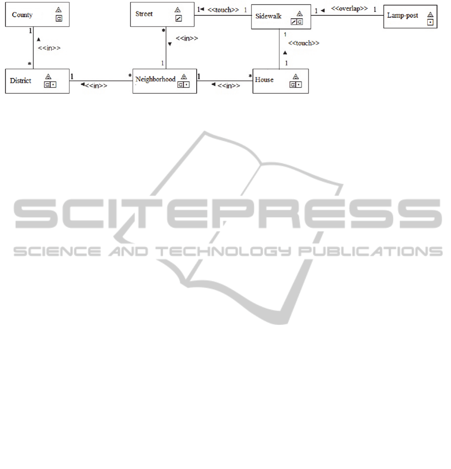
Figure 3: Example of an UML-GeoFrame diagram for urban administration.
Code 8: OCL expression for County and District.
context District
inv: self.area.in.County.area
inv: self.point.in.City.area
Observing a relationship between District and
Neighborhood, where all classes have multiple
representations, it is possible to define that the
relationship between these classes would result in
four distinct combinations of relationship:
Area/Area, Area/Point, Point/Point, Point/Area.
However, when realizing the validation of this class
using the OCL code of section 3.1, this relationship
will return an invalid one, once the area cannot be
inside a point. Therefore, only an arrow and the
stereotype are not enough, thus requiring the using
of the OCL expression. Besides, only two
relationships of these combinations are being
considered valid, and will be represented in Code 9.
These relationships are possible between Area
and Area, where the area of a Neighborhood must be
inside the area of a District, and between Point and
Area, when the coordinates of the points of the
Neighborhoods serve only to store the mapping of
the Neighborhoods inside an area of a district.
The Relationship between Neighborhood being
Area and District being Point are not possible not
even topologically, as it can be seen in Section 2.
Other relationship that is not possible in this
example is Neighborhoods being Point and District
also being a Point. Although it is topologically
possible, it does not make sense since the point
coordinates stored for each Neighborhood relate
only to the mapping of those within the district area.
With four different approaches about the possible
and impossible cases, as well as those without
relation, it becomes important to complement the
diagram through the OCL. Code 9 addresses the
cases Area/Area and Point/Area between
Neighborhood and District to reinforce during the
project that only these are important. If the topologic
relationship inside were specified in the
Neighborhood and District, considering Area/Point,
the verification of the OCL expression should return
false. And finally, although between Point/Point the
topological relationship may exist, as presented in
section 2, in this example it is not necessary since it
is not a constraint of the problem.
Code 9: OCL expression for Neighborhood and District.
context Neighborhood
inv: self.area.in.District.area
inv: self.point.in.District.area
The same occurs for the relationship between the
classes Neighborhood and Street.
The relationship
shows that one Street must be inside one
Neighborhood and only the relationship involving
line and area can be considered valid. The
relationship between line and point is invalid,
because it is not possible that a line is inside a point.
This relationship will be considered invalid when the
diagram is validated by an OCL expression
presented in section 3.1. Therefore, in this example
it is fundamental that the designer uses the OCL to
remove these ambiguities to which the geometry pair
of topological relationships refers. Code 10 shows
the OCL expression for this relationship.
Code 10: OCL expression for Street and Neighborhood.
context Street
inv: self.line.in.Neighborhood.area
The relationship between the classes Lamp-post
and Sidewalk, shows that a lamp-post must overlap
a sidewalk. The overlap relationship between the
pairs of geometric elements Point/Line and
Point/Area is not considered valid since, according
to section 2, the point has no overlap relationship
with any geometric type. When using the OCL
expression to validate this diagram, it would return
that both relationships are invalid. As presented in
section 3.2, in this case the designer must reevaluate
this relationship since it was certainly modeled in an
incorrect way.
Analyzing the possible relationships between the
classes, the topologic relationship must be modified
to the inside type to be modeled correctly.
ICEIS2013-15thInternationalConferenceonEnterpriseInformationSystems
292

When using the OCL expression to validate this
diagram in order that it has a valid relationship,
although there is a class that contains multiple
representations (Sidewalk), it is not necessary to use
the OCL expression, since a Point can be inside a
Line, as well as a Point can be inside an Area. In this
case, an OCL expression informed by the designer
can be used only if one wants to reinforce what is
expressed in the diagram.
5 FINAL CONSIDERATIONS
AND FUTURE WORKS
This paper aimed at demonstrating that the
conceptual modeling of databases can be performed
in order to specify all the requirements of stored data
required to the application.
This work demonstrates an effort that has been
performed so that the conceptual modeling of
geographical databases can be realized, in a way to
specify all the data storage requirements that is
required by the application. This work aims to show
that OCL expressions extended with common
constructors of the geographic databases area can aid
in conceptual modeling using UML-GeoFrame.
Just like it happens in default UML, the OCL can
be used to verify if the model constructors are being
used in the right way. More specifically in this
context, OCL is used to verify if the topological
constraints that exist between the geographical
elements present in the diagram are being specified
correctly, thus eliminating the errors found from the
modeling data. Furthermore, it is also proposed the
use of OCL inside the own UML-GeoFrame data
model to validate the extended OCL expressions
defined by the user.
These objectives were reached through the
incorporation of geographical constructors in the
OCL language and its use with the UML-GeoFrame
model, thus making a precisely conceptual
modeling, without ambiguities and according to the
UML specifications.
In future works, it is intended to implement the
extended OCL in a CASE tool. Thus, it will be
possible to realize an automatic validation of the
expressed spatial relationships in the diagram and in
the OCL expressions. Furthermore, it is also
intended to implement an automatic SQL
code-generation module to geographical databases,
capable of processing user defined constraints.
ACKNOWLEDGEMENTS
This project is partially financed by FAGOC,
CAPES, FAPEMIG and CNPq/MCT/CT-INFO.
REFERENCES
Clementini, E.; Di Felice, P.; Oosterom, P. 1993. A Small
Set of Formal Topological Relationships Suitable for
End-User Interaction. In: International Symposium on
Advances in Spatial Databases.
Dietrich, S. W.; Urban, S. D. An Advanced Course in
Database systems: beyond relational databases.
Prentice Hall, 2005
Duboisset, M.; Pinet, F.; Kang, M.; Schneider, M. 2005.
Precise Modeling and Verification of Topological
Integrity Constraints in Spatial Databases: From an
Expressive Power Study to Code Generation
Principles. In: International Conference on
Conceptual Modeling, 24, Klagenfurt.
Egenhofer, M. J.; Franzosa, R. D. 1991. Point-set
topological spatial relations. International Journal of
Geographic Information Systems, v.5, n.2, p. 161-174.
Lisboa Filho, J.; Iochpe, C. 1996. Adaptando o modelo de
objetos OMT para modelagem conceitual de
aplicações de SIG. In: 1
a
SEGEO-RJ – Semana
Estadual de Geoprocessamento, Rio de Janeiro.
Lisboa Filho, J.; Stempliuc, S. M. 2009. Modeling spatial
constraints in conceptual database design of network
applications. In: Urban and Regional Data
Management (UDMS), Ljubljana, p. 185-193.
OMG. 2012. Documents Associated With Object
Constraint Language, Version 2.3.1, January 2012.
OMG. 2011. Documents Associated With Unified
Modeling Language (UML), Ver. 2.4.1, August 2011.
Warmer, J.; Kleppe, A. 2003. The Object Constraint
Language: Getting Your Models Ready for MDA. 2.
Ed. Bostons: Addison Wesley.
ExtendingOCLtoSpecifyandValidateIntegrityConstraintsinUML-GeoFrameConceptualDataModel
293
